
Abstract
Transverse injection into supersonic flow after rearward-facing step combines a simple way to improve mixing and flameholding in Scramjet engines. In this essay, large-eddy simulation, NPLS, and PIV techniques are applied to study the flow characteristics of a sonic jet with different flow rates after rearward-facing step interacting with supersonic turbulent flow. Results show that since a big recirculation zone is generated by rearward-facing step before the jet, the barrel shock in the windward side is not so obviously compressed so that jet fluid enters the recirculation zone providing a flammable region for ignition and combustion stabilization. Besides, jet fluid bypassing the Mach disk comes directly into interaction with the turbulent boundary layer separated from the rearward-facing step to enhance vortices development in the further downstream. The comparisons of average boundaries abstracted from NPLS images with empirical penetration height equations show that mixing enhancement of transverse injection into supersonic flow after rearward-facing step has a close relationship with the jet to free-stream momentum. In small jet to free-stream momentum case, the mixing shear layer grows mainly in the near field of the jet, while in big jet to free-stream momentum case, the growth of the mixing shear layer could extend to the far-field wake flow zone of the transverse jet.
1. Introduction
The flow field inside a supersonic combustor is highly complex and presents a considerable challenge in developing a combustor geometry and a fuel injection control method which promote sufficient mixing of the air and fuel. Transverse fuel injection behind a rearward-facing step is a flow configuration that has been suggested as a means of enhancing mixing and combustion completeness (the jet flow direction is vertical to the main flow direction). For the case of supersonic upstream flow, injecting fuel transversely behind a rearward-facing step enables the jet to penetrate well into the (locally lowspeed) flow before being turned by supersonic cross-flow. And the rearward-facing step is treated as a simple flameholding device by generating a continuous high temperature ignition kernel formed in the recirculation zone to stabilize the flame.
Several experimental and numerical investigations have been conducted to understand the mechanisms of the jet mixing and flameholding behind a rearward-facing step. Karagozian et al. [1, 2] combined experimental data of transverse gas injection behind a rearward-facing step with theoretical analysis to develop a model for jet trajectories prediction. Aider and Danet [3] conducted large-eddy simulation to investigate the influence of upstream boundary conditions on the development of a rearward-facing step flow. Thakur and Segal [4] used planar laser induced fluorescence (PLIF) and mass spectrometry (MS) techniques to study the nonpremixed flameholding mechanism behind a step in supersonic flow. Behrens et al. [5] utilised reacting flow PIV to investigate flame anchorability behind a rearward-facing step by varying the equivalence ratio and near-field counterflow.
However, among all these investigations, little has been done to capture the fine structures generated by the interaction of the transverse jet behind a rearward-facing step and the supersonic main flow under turbulent inflow condition. Besides, the mixing enhancement mechanism under different jet to free-stream momentums is not quite clear.
2. Experiment Setup
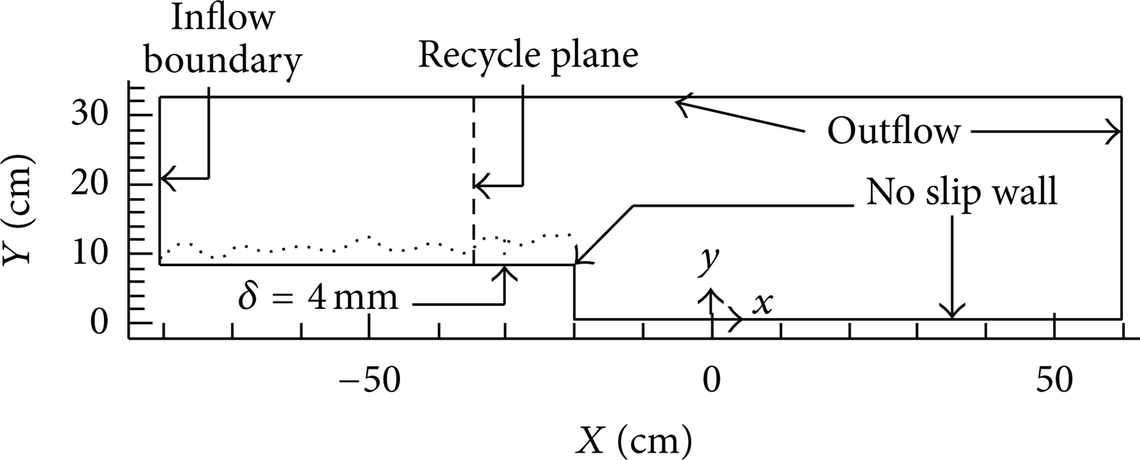
All of the experiments have been performed in a low-noise wind tunnel at Mach 2.7, a stagnation pressure of P0 = 101325 Pa, and stagnation temperature of T0 = 300 K, with the corresponding unit Reynolds number R el = 8.79 × 10⁶ (the reference length is 1 m). The tunnel has been well described in the former work [6, 7] and for brevity the introduction of the whole system will not be repeated here. The x-y-z coordinates are defined in Figure 1 and the origin point is defined at the jet exit center. The spanwise length of the experimental section is 196 mm. In the middle of the spanwise direction, a jet with Mach 1.0 is injected after the rearward-facing step as described in Figure 1. The high spatiotemporal resolution NPLS (nanoparticle-based planar laser scattering) [8] and PIV (particle image velocimetry) techniques are applied to observe the flow field.

Schematic of the experimental section.
Two nitrogen injection conditions, represented by No. 1 and No. 2, are shown in Table 1. In order to stabilize the stagnation pressure of the injection, a nitrogen digital controller for small mass flow rate (Sevenstar CS230 Mass Flow Controller) is used. The controller could be set manually at certain volume-flow rate which corresponds to the mass flow rate number by multiplying a conversion parameter. In this study, No. 1 is set at the flow rate 30 SLM (standard liter per minute) and No. 2 at the flow rate 90 SLM. The corresponding mass flow rates and momentum flux ratio to mainstream are listed in Table 1. The diameter of the nitrogen injection orifice is 2 mm.
Experimental injection conditions.

3. Mathematical Models
3.1. Turbulence Models
Here, a hybrid RANS/LES approach based on the one-equation S-A RANS model [9] and the one-equation Yoshizawa SGS model [10] is used, which maintains the robustness of the one-equation model but essentially eliminates some shortcomings of DES (detached eddy simulation) [11]. This hybrid method is similar to that of Baurle et al. [12], but they have used BSL model for the RANS part near wall.
3.2. Numerical Schemes
In the present study, the fifth-order WENO scheme developed by Jiang and Shu [13] is used for inviscid fluxes, the remarkable capability of which in resolving complicated shock and flow structures is demonstrated in that study. Viscous fluxes are discretized by means of a second-order-accurate centered scheme. In view of improving the computing efficiency, the time integration is performed by means of a second order, implicit dual time step approach, the inner iteration of which is achieved by a LU-SGS method.
3.3. Turbulent Inflow Conditions
Recycling/rescaling method is used to treat the turbulent inflow condition, which is considered to be a promising way to prescribe time-dependent turbulent inflow conditions for LES or hybrid RANS/LES of spatially developing turbulent flows [14–17]. In the present study, a method similar to that of Xiao et al. [16] is used.
The high resolution NPLS image of turbulent boundary layer before rearward-facing step is shown in Figure 2 (a), from which the coherent structures in the inner layer and the outer layer could be well distinguished. The PIV measured boundary layer thickness at 10 centimeter before the rearward-facing step is estimated to be δ = 4 mm. The turbulent boundary layer at this position in recycling/rescaling method is promised to be the same with the experiment as shown in Figure 3.
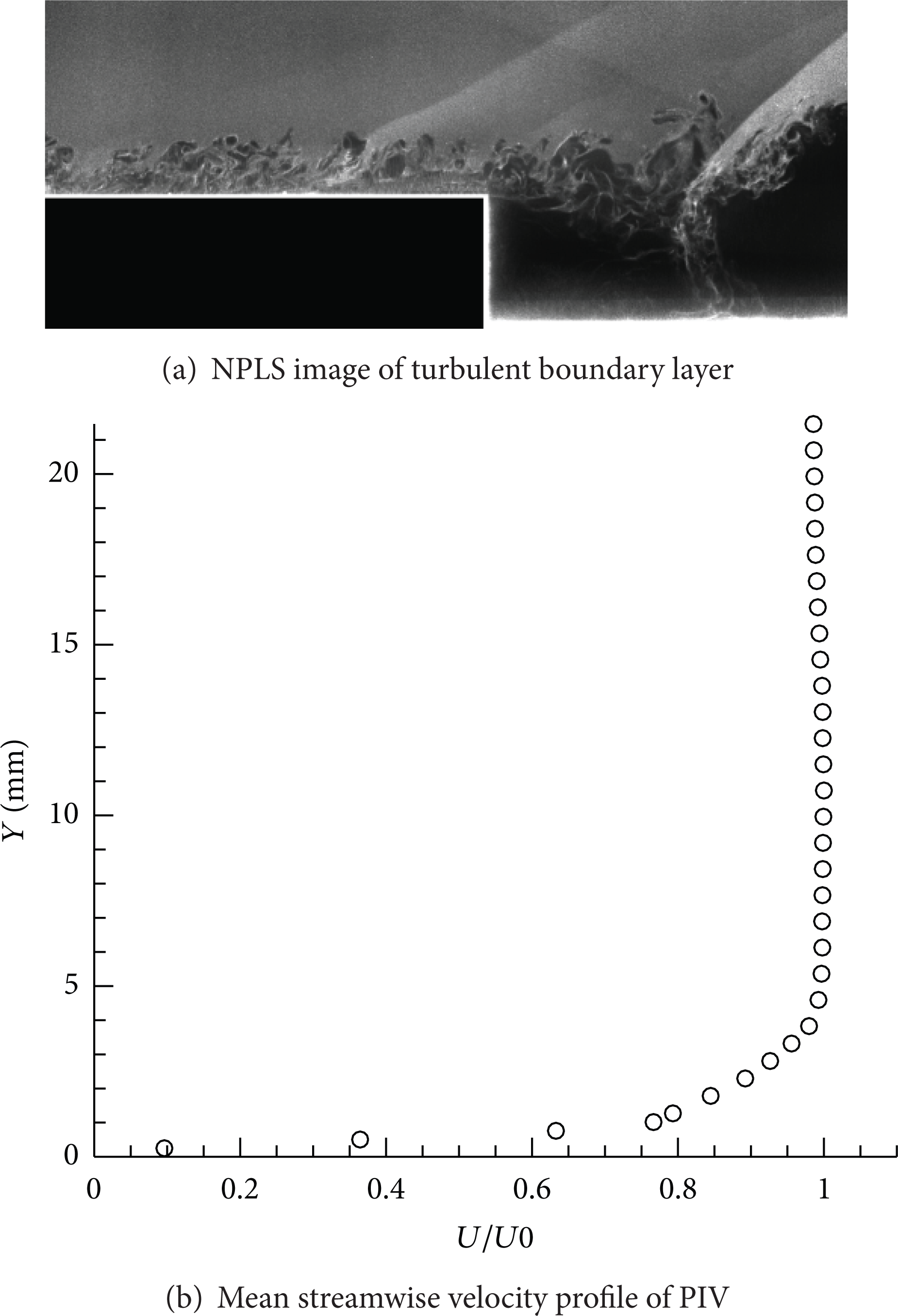
NPLS image of turbulent boundary layer and the mean streamwise velocity profile of PIV.
Recycling/rescaling procedure.
The computational domain is L x = 35δ, L y = 8δ, and L z = 5δ, where x, y, and z denote the streamwise, transverse, and spanwise directions, respectively. The injection location and jet Mach number are same with the experimental setup. The number of grid points is about 9.7 million, and the mesh is refined near wall and injection region to assure that Δx+ ≈ 30, Δz+ ≈ 20, and Δy+ ≈ 1 ~ 20.
4. Results
4.1. Discussion of Flow Characteristics
From Figure 4, one can tell that the flow characteristics of sonic jet with different flow rates after rearward-facing step interacting with supersonic flow are quite similar with those of direct injection into supersonic cross-flow; it is possible to divide the entire flow field into five regions, shown in Figure 4. Region I is the incoming turbulent boundary layer zone. Region II is the zone where jet fluid enters the recirculation zone and the zone including the interaction of recirculation shear layer and the incoming flow. In region around the jet exit, that is, region III, a bow shock is observed ahead of the jet, barrel shocks are observed at its periphery, the jet fluid forms a Mach disk as it expands into and bends toward the cross-flow, and the interface or shear layer in the near-field jet region is confronted with the flow behind the bow shock. Region IV is the near-field wake flow zone of the transverse jet, where jet fluid bypassing the upstream of the Mach disk comes into interaction with the incoming turbulent boundary layer to prominent large scale coherent vortices in high shear downstream and the nanoparticles transported from the upstream reflect the wake flow structures. Region V is the far-field wake flow zone of the transverse jet, and it includes the mixing shear layer between far-field jet and the main air stream, and in high shear downstream, some reattachment shocks are observed.

NPLS images and two color density contours on symmetry plane of calculation. D denotes the height of the rearward-facing step.
Injection after rearward-facing step shows some significant differences from direct injection. First, due to the reason that the injection is after the rearward-facing step, the barrel shock in the windward side is not so obviously compressed by the incoming flow behind the bow shock as in the direct injection into supersonic cross-flow, which results in jet fluid entering the recirculation zone represented by the dark region after rearward-facing step in Figure 4. Mixing procedure in the recirculation zone provides a flammable region for ignition and combustion stabilization. Second, the bow shock is formed at the upper side of the barrel shock so that jet fluid bypassing the Mach disk comes directly into interaction with the turbulent boundary layer separated from the rearward-facing step. The flow velocity behind the bow shock decreases and the incoming coherent structures of turbulent boundary layer collide with the jet to form the shear layer. Small scale structures originate in the shear layer, where some small eddies come from the upstream turbulent boundary layer directly to enchance mixing. In a short distance, before the jet completely bends, the small scale structures grow to large ones.
Figure 4 also visualizes the comparison between instantaneous experiment results and numerical results of the two injection conditions mentioned above. It is shown that turbulent boundary layer of simulation is well sustained, and the large-eddy structures of two injection conditions are well captured, and the flow pattern has a good agreement with the experimental results. In order to further discuss the differences, mean streamwise velocity profiles extracted from PIV results are compared with simulation in Figure 5. It is concluded that, under the rearward-facing step, simulation results of both conditions deviate from experiments a lot. Because there is just a small portion of nanoparticles entering the region below the rearward-facing step, so the velocity contours measured by PIV are not quite accurate in this region. At locations of X/D = 1,3, 5,30 SLM case has a better agreement with experiment than 90 SLM case.
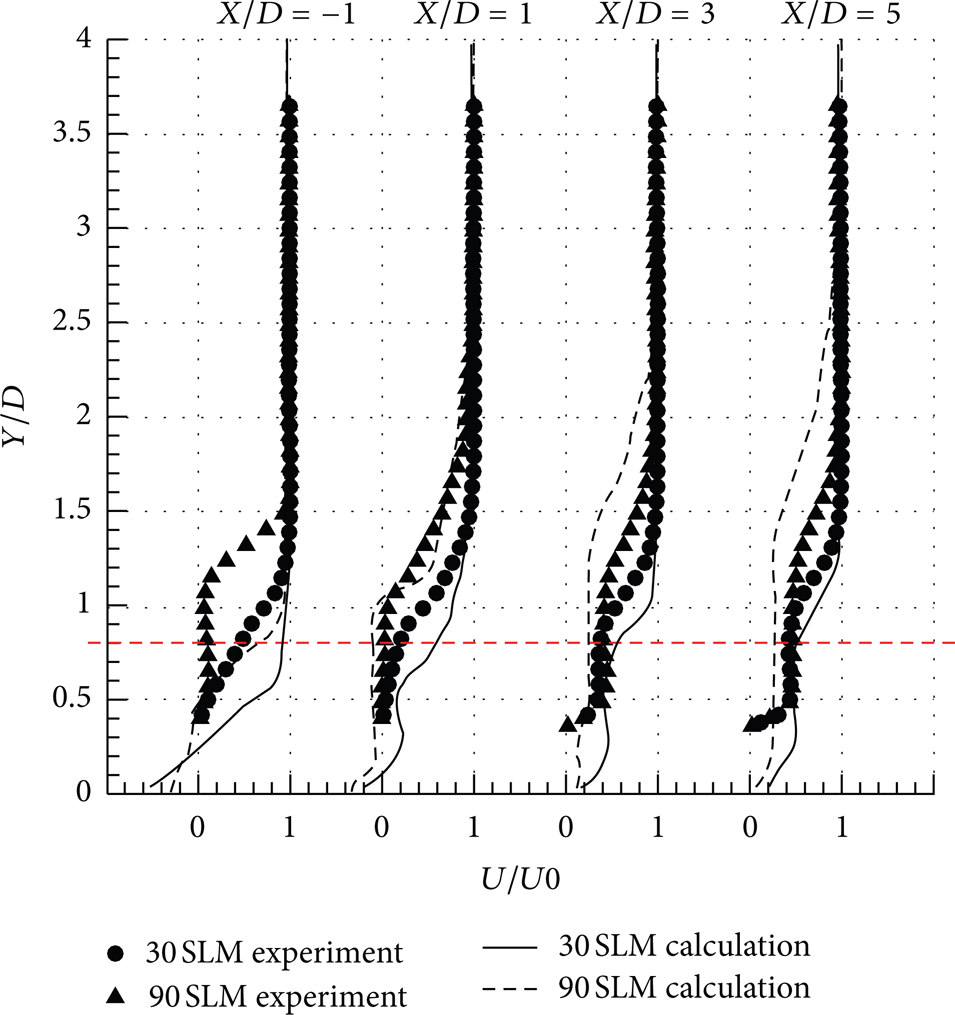
Mean streamwise velocity profiles of experiment and calculation at different locations. The red line represents the position of the rearward-facing step in y direction. Symbols represent experimental results, and lines stand for simulation.
4.2. Discussion of Mixing Enhancement
In contrast to jet injection into a uniform cross-flow, injection behind a step introduces a clear sensitivity to the location of jet introduction [1]. In order to increase the penetration height of the jet injection behind the rearward-facing step, the injection position is located after the rearward-facing step in the recirculation zone as shown in Figures 1 and 4.
In Figure 6, the average boundaries of two conditions were obtained by averaging penetration boundaries of 30 NPLS images. Two empirical penetration equations suggested by Rothstein and Wantuck [18] and Gruber et al. [19] which are widely used to predict the penetration heights of different injection conditions were chosen to compare with experimental results. In the near-field wake flow zone of transverse jet, due to the reason that the injection is located in the recirculation zone, jet fluid could reach higher which enhance mixing with mainstream, so in the region around the jet exit and near-field zone of both conditions, the empirical equations have underestimated the penetration height. While in the far-field wake flow zone, the penetration height of the transverse jet decreases significantly with the jet momentum. This could be explained by the reason that the jet fluid which reaches higher in the zone around the jet exit and near-field wake flow zone of the transverse jet only contributes to a small fraction of the total jet mass. In the downstream of the wake flow zone, the normal velocity of the jet fluid becomes smaller than upstream so that the effect of the shear layer between far-field jet and the main air stream becomes dominant.

Average boundaries of two conditions abstracted from NPLS images compared with empirical penetration height equations.
Figure 7 further explains the effect of interaction between jet and rearward-facing step on penetration height. Temperature contours are useful in visualizing shear layer. From Figure 7, it is observed that the shear layer in the recirculation zone is obviously affected by the transverse injection because a certain amount of jet fluid enters the recirculation zone. Larger injection momentum enlarges N2 mass fraction in the recirculation zone which causes the angle between the shear layer and main flow to be smaller so that the jet is less affected by the incoming flow. In 30 SLM injection case, the shear layer grows a bit in the region around the jet exit but decreases in the near-field wake flow zone and maintains a certain level in far field. However, in 90 SLM injection case, the difference lies in that the shear layer in the near-field wake flow zone still grows and thus can enhance mixing.

Average temperature contour of numerical results on central plane.
From the instantaneous simulation results, the mixing enhancement is shown in Figure 8; the counter-rotating vortices as well as the hairpin-like vortices in the far field are captured by the mathematical model applied in this essay. The counter-rotating vortices generated by jet and cross-flow interaction in the wake flow zone are covered by turbulent incoming flow vortices, and hairpin-like vortices are highly twisted. It could be seen that, in the near-field wake flow zone of 90 SLM case and in the region around the jet exit of 30 SLM case, the vortices could reach higher than direct injection as showen in Figure 6 so that the mixing in these areas is enhanced.
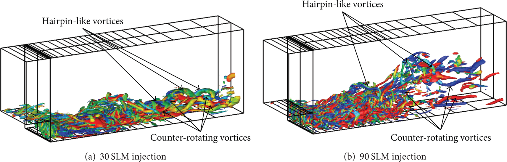
The second invariant of the velocity-gradient tensor (Q = 0.2) colored by the streamwise vorticity.
Jet fluid N2 mass fraction contours on two conditions are shown in Figure 9. Figure 9 indicates that the transverse jet penetration after rearward-facing step has a close relationship with the jet to free-stream momentum. In big jet to free-stream momentum condition (i.e., the 90 SLM injection case), the penetration height grows significantly from the jet exit to the far-field wake flow zone compared with small jet to free-stream momentum condition (i.e., the 30 SLM injection case). The fierce interaction between main flow and transverse injection is mainly observed in the near field of the jet in both conditions. Pressure contours parallel to the wall in Figure 9 show the horseshoe vortex shape ahead of the jet on two conditions. With higher jet to free-stream momentum, the pressure after the injection location is much higher which contributes to the jet penetration.

Jet fluid N2 mass fraction contours on cross-planes and the pressure contour on the horizontal plane.
5. Conclusion
In the present work, the flow characteristics and jet mixing of gaseous transverse jet into supersonic flow after rearward-facing step are studied by numerical and experimental methods.
It is possible to divide the entire flow field into five regions. The flow characteristics differ from those of direct injection into supersonic cross-flow. A big recirculation zone is formed in Region II so that the barrel shock in the windward side is not so obviously compressed so that jet fluid enters the recirculation zone providing a flammable region for ignition and combustion stabilization. Besides, the direct interaction between jet fluid bypassing the Mach disk and the turbulent boundary layer separated from the rearward-facing step has a great impact on vortices development in the further downstream.
Simulation and experimental results compared with empirical equations show that mixing enhancement of transverse injection into supersonic flow after rearward-facing step has a close relationship with the jet to free-stream momentum. In small jet to free-stream momentum case, the shear layer grows mainly in the near field of the jet, while in big jet to free-stream momentum case, the growth of the mixing shear layer could extend to the far-field wake flow zone of the jet.
Footnotes
Acknowledgments
The research work was funded by the National Natural Science Foundation of China (no. 91116001) and Fok Ying Tung Education Foundation under Grant no. 131055.