
Abstract
Based on finite volume method, the interaction between base jet and supersonic flow around the rocket is simulated by Navier-Stokes equations with SST k-ω turbulence model and implicit algorithm. The pressure contours, the streamline patterns, and the variation of the aerodynamic characteristics of the rocket with the flying altitude, Mach number, and the angle of attack are shown and analyzed. Numerical results demonstrate that in supersonic flow, the base jet has a noticeable effect on the surface pressure of the body and the tails, leading to the decreases of the coefficients of the normal force, the pitching moment, and the pressure center. Furthermore, the higher the flying altitude, the more grave decreases of the coefficients of the normal force, the pitching moment and the pressure center. However, with the increase of Mach number, the more grave the decreases of the normal force coefficient and the pitch moment coefficient are found, while the less grave decrease is found with the pressure center coefficient. With the increase of the angle of attack, the more grave decreases are found with the coefficients of the normal force and the pitching moment, while the decrease of the pressure center coefficient remains almost the same.
1. Introduction
In recent years, rockets of all kinds and patterns have turned out to be more and more important in modern local wars, as is seen in Iraq and Afghanistan, for their abrupt, violent, intensive fire and good maneuverability. Therefore, a lot of countries have committed to the development of rocket weapon systems, demanding not only more accurate operation, but also higher, faster, and farther launching conditions. Practically speaking, with the increase of the flying speed and the altitude, the aerodynamic characteristics of the rocket change greatly especially when the base jet is on in the active segment. Therefore, under the conditions of supersonic flow and high altitudes, the effects of the base jet on the aerodynamic characteristics and flying stability of rockets have become the hot topics for the researchers nowadays.
As early as in the 1950s, the rocket engineers and scientists began to turn their attention to the free-flight investigation [1] over a Mach number range from 0.6 to 2.0 with the purpose of investigating the effects of the base jet on the drag force of 1/5-scale model of Hermes A-3A at α = 4 ° −8 °. Their research demonstrated that the effects of the base jet on the drag characteristics are various due to different Ma and p j /p∞.
Since then, numerous experimental studies [2–11] have been done to determine the interaction between the base jet and the supersonic flow around the projectile from the 1960s to the beginning of the 21st century. For example, in 1998, Banning et al. [8] did a large amount of research on the flowing characteristics of the interaction flowfield in TST-27 transonic and supersonic wind tunnel. The selected geometry was axisymmetric having a spherically blunted cone as forebody and an equal-length cylinder as afterbody, with the total length of the model being 186.81 mm and the diameter being 50 mm. To be exact, under the condition of Ma = 1.96,2.98, it would be possible to obtain the Schlieren figures of the interaction between the base jet and the supersonic flow around the projectile, so was the surface pressure of the afterbody and the base.
In 2006, an experimental investigation has been done by Lin et al. [11] to determine the interaction between the base jet and the supersonic flow around the missile body in the hypersonic propulsion wind tunnel, in which the Mach number equals 4, the angle of attack is from 0° to 6°, and the analog altitude is 44 km with the cold air as the jet medium. Moreover, the investigation obtained the Schlieren figure of the interaction between the base jet and the supersonic flow around the missile body, as well as the axial force coefficient, the normal force coefficient, and the pressure center coefficient of the missile. The results of his experiment prove that when the jet is on, the base pressure of the missile tends to increase, while the base drag tends to decrease and so do the longitudinal aerodynamic coefficient and the pressure center coefficient.
As we know that although the free-flight tests and wind tunnel experiments are rather accurate and valuable, they turned out to be comparatively complicated in operation, economically inappropriate, and inefficient.
With the further development of computational fluid dynamics, more and more researchers [11–17] have begun to commit themselves to the numerical simulation of the interaction between the base jet and the supersonic flow around the missile body from the 1990s to the early 21st century. However, all these studies were mainly focused on the missiles of small length-to-diameter ratio L/D with no regard of their tails.
This paper mainly aims to study the interaction between the base jet and the supersonic rocket, of greater length-to-diameter ratio L/D, with tails. The chief purpose of this paper is to analyze the effects of the base jet on the surface pressure of the rocket body and its tails and to explore the effects on the aerodynamic characteristics and the static stability of the rocket.
2. Numerical Simulation Method
2.1. Governing Equation
The dominant equations are the integral form of the three-dimensional Navier-Stokes equations, which can be written as

where the Vector H denotes the source term and the Vectors W, F, and G can be defined, respectively, as
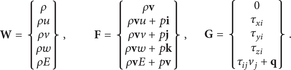
In (2), ρ,
Herein, the relation between E and H can be rewritten as follows:

In (3), H can be defined as
2.2. Turbulence Model
The Menter Shear-Stress Transport Model (k-ω SST model) effectively blends the robust and accurate formulation of the k-ω model in the near-wall region with the free-stream independence of the k-ε model in the far field. Furthermore, it is necessary to take into account damped cross-diffusion derivative term and the transport of the turbulent shear stress. Hence, the k-ω SST model can be effectively adapted to simulate the interaction of the base jet with the supersonic flow around the rocket body, as is shown below:


In (5), G k represents the generation of turbulence kinetic energy due to the mean velocity gradients, and Gω represents the generation of ω. Γ k and Γω represent the effective diffusivity of k and ω, respectively. Y k and Yω represent the dissipation of k and ω due to turbulence, and Dω represents the cross-diffusion term. S k and Sω are self-defined source terms.
2.3. Numerical Method
Based on the finite volume method, this paper discretizes the control equations by means of coupled implicit algorithm, including discretization of the convection and the diffusion via the secondary order upwind approach.
2.4. Boundary Conditions
The outer boundary of the computational domain can be taken as the far-field pressure boundary conditions. At the same time, the rocket surface, the wing surface, and the nozzle wall are taken as adiabatic wall. When the jet is on, the cross-section of the nozzle throat is taken as the inlet boundary; the static pressure, the static temperature, and the inlet velocity of the jet are given at the cross-section of the nozzle throat. However, when the jet is off, the cross-section of the nozzle throat is regarded as adiabatic wall.
3. Model and Mesh
3.1. Model and Conditions
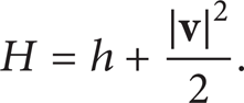
Figure 1 shows the configuration of the rocket we have proposed, which is supposed to be one with four tailing wings in the shape of a big ×. To be exact, the body of the simulated rocket has a length L = 12 m and a body diameter D = 0.6 m. In addition, the root chord length of its tails b0 is 1.5 m, and the tail tip chord length b1 is 1 m. The full-span of the tail has a length L T = 1.6 m and a thickness c = 0.02 m. Finally, the nozzle throat diameter D* is 0.1 m, and the nozzle exit diameter D e is 0.3 m.

The cone-like cylindrical tail model.
The numerical conditions are illustrated as follows: the free stream Mach number Ma = 2–6, the angle of attack α = 2°–10°, and the altitude h = 0 km–20 km. In order to simplify the calculation, the jet medium is taken as the air [18–21], the static pressure of the nozzle throat p t is 1.585 × 10⁷ Pa, and the static temperature of the nozzle throat T t is 3000 K.
3.2. Mesh
The computational domain is discretized by a structured grid which is refined in the interior structure of the body end, the junction of the tails and the body, the nozzle exit, and the shear layer. In addition, since both the whole missile configuration and flow field are symmetric, only one half of the computational domain is simulated to reduce the calculation amount. In order to exclude the effect of the grid on the simulation results, the aerodynamic characteristics obtained by two grids, respectively, having a grid number of 3 million and 5 million have been compared, and they differ a little; thus considering the calculation efficiency, the grid number of the grid adopted is 3 million. Figure 2 intends to show the grid of the computational domain to be discussed. Figure 2 (a) shows the local grid of the model, and Figure 2 (b) demonstrates the grid of the cross-section of the computational domain.
The grid of the computational domain.
4. Numerical Simulation and Method Assessment
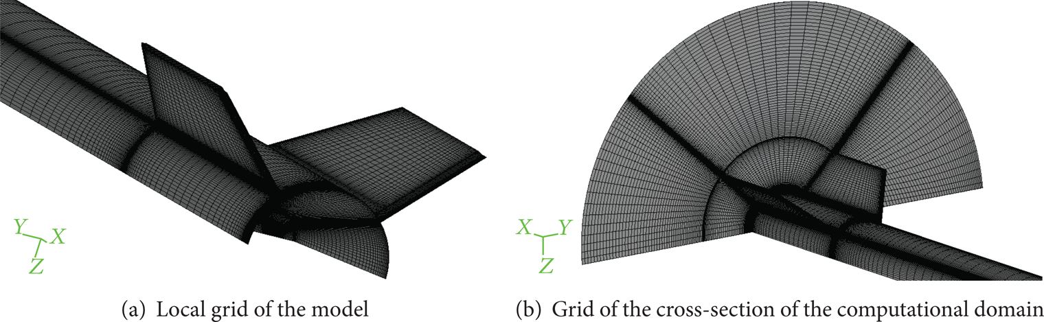
In this part, we would like to verify the practicalities of the numerical method. As is seen above, the simulation we have done is based on the same missile model as is shown in [2] under the condition of Ma = 1.96 and p e /p∞ = 2.469. Figure 3 depicts the surface pressure coefficients obtained both by the simulation in this paper and the experiment quoted in [2], indicating that the numerical results of ours are in accordance with the experimental data mentioned in the corresponding reference. Figure 4 shows the structures of the flowfield obtained by both the simulation in this paper and the experimental results mentioned in [2]. Figure 4 (a) is the Schlieren figure from [2], and Figure 4 (b) is the pressure contour in the symmetrical plane obtained by the given numerical simulation. As is shown in Figure 4 (b), the numerical flowfield contains the barrel shock, the plume shock, and the shear layer at the base of the missile body, which also proves to be consistent with the experimental data. Thus, the results we have gained in this simulation indicate that the numerical method developed in this paper is feasible for the exploration of the interaction between the base jet and the supersonic flow around the rocket.

Computational and experimental pressure distribution along cylinder leeward generator (Ma = 1.96, p e /p∞ = 2.469).
The structure of the flowfield obtained by the simulation and the experiment with Ma = 1.96 and p e /p∞ = 2.469.
5. Results and Discussions
5.1. Interaction Flowfield
Figure 5 shows the pressure contours and the streamline patterns of the base area of the rocket in the longitudinal symmetric plane under the conditions of Ma = 2, α = 2°, and h = 20 km. As shown in Figure 5 (a), once the jet is off, the airflow around the rocket flows through the base of the rocket, and the expanding waves are formed at the rear side. After the airflow passes through the expanding waves, the pressure becomes lower, but the speed goes up. Subsequently, a reflux is formed in the nozzle throat at the base of the rocket. However, as shown in Figure 5 (b), in the case of the jet being on, the underexpanded jet from the nozzle goes on expanding, leading to further increase of the speed and decrease of the pressure. Since the pressure of the jet is still high, a huge pressure difference is formed between the flow field around the rocket and the base jet, leading to a shock wave. At this moment, when the supersonic flow around the rocket passes through the shock wave, the pressure increases to the same level as that of the jet and the flowing direction turns to be the same as that of the jet eventually, resulting in a slipstream surface being formed between the jet and the flow around rocket. In addition, due to the mutual interaction between the jet and the flow around the rocket, the shock wave caused by the huge pressure difference tends to be pushed forward, which results in significant variation of the pressure distribution around the afterbody of the rocket.

Pressure contour and streamline of the base region in the longitudinal symmetry plane (Ma = 2, α = 2°, and h = 20 km).
5.2. The Variation Regularity of the Aerodynamic Characteristics with the Flying Altitude and Flow Mechanism
Figure 6 shows the curves of the normal force coefficient C
N
, the pitching moment coefficient mzg0, and the pressure center coefficient

The variation of aerodynamic characteristics of rocket with h at Ma = 2, α = 2°.
Figure 7 shows the pressure distribution contours of the tails and the rear region of the rocket body under the conditions of Ma = 2, α = 2° with h = 5 km, 10 km, 15 km, and 20 km, with the jet being either on or off, respectively. It can be seen from Figures 7 (a) and 7 (b) that the jet increases the surface pressure of the rear region of the body when h = 5 km but has no effect on the pressure distribution of the tails. And Figures 7 (c) and 7 (d) show that the effect of the jet on the surface pressure of the rear region of the body becomes greater in range when h = 10 km. Furthermore, for the tails, the surface pressure of partial region is also enhanced due to the jet. As shown in Figures 7 (e)–7 (h), the effect of the jet on the surface pressure of the tails increases when h = 15 km and h = 20 km. Furthermore, the effect on the leeward side can be found much greater than that on the windward side, which leads to a great pressure difference and a large negative normal force, resulting in an unsteady pitching moment, thereby leading to the decrease of the static stability and the forward movement of the pressure center.

Pressure contours of the tails and the rear region of the body at different h (Ma = 2, α = 2°).
Since the effects of the base jet on the upper and lower sets of the tails are similar, it is only necessary to analyze the effect of the base jet on the lower set of the tails.
Figures 8–11 show the pressure distribution contours at different cross-sections under the conditions of Ma = 2, α = 2° with h = 5 km, 10 km, 15 km, and 20 km, with the jet being either on or off, respectively. Since the total length of the rocket is 12 m and the distance between the trailing edge of the tail and the base of the body is 0.05 m, the cross-section x = 12 m is located at the base of the rocket body, while the cross-section x = 11.95 m is the one located at the trailing edge of the tail.

Pressure contours at different cross-sections (Ma = 2, α = 2°, and h = 5 km).

Pressure contours at different cross-sections (Ma = 2, α = 2°, and h = 10 km).

Pressure contours at different cross-sections (Ma = 2, α = 2°, and h = 15 km).

Pressure contours at different cross-sections (Ma = 2, α = 2°, and h = 20 km).
However, when h = 5 km, as shown in Figures 8 (a) and 8 (b), the jet leads to the increase of the surface pressure in the partial region where the cross-section x = 12 m. Comparing Figure 8 (c) with Figure 8 (d), we can find that the jet has little effect on the surface pressure at the cross-section x = 11.96 m. Thus, it can be said that the jet has little effect on the surface pressure distribution of the tails. Therefore, the jet has a minor effect on the pressure center coefficient of the rocket when h = 5 km.
When h = 10 km, as shown in Figures 9 (c) and 9 (d), the jet increases the surface pressure of the tails at the cross-section x = 11.95 m, whereas Figures 9 (e) and 9 (f) indicate that the jet has no effect on the surface pressure of the cross-section of x = 11.92 m. Therefore, as compared with the case whose flying altitude is h = 5 km, the effect of the jet on the pressure center coefficient increases slightly when h = 10 km. Furthermore, Figures 9 (c) and 9 (d) also show that the jet also increases the surface pressure of the tails at the cross-section x = 11.95 m, though it has no effect on the surface pressure of the rocket body. Therefore, the effect of the jet on the surface pressure of the tails is much greater than that of the rocket body, indicating that the presence of the tail may lead to the increase of the effect of the jet.
Figures 10 and 11 show that when the flying altitude reaches h = 15 km and h = 20 km, the base jet increases the effects on the surface pressure of the tails and the rocket body significantly. Furthermore, the effect on the leeward side is greater than that on the windward side. When h = 15 km, as shown in Figures 10 (e) and 10 (f), the jet does not have any more effect on the surface pressure of the windward side at the cross-section x = 11.9 m. Comparing Figure 10 (g) with Figure 10 (h) shows that the jet does not have any more effect on the surface pressure of the leeward side at the cross-section x = 11.82 m. Furthermore, when h = 20 km, as shown in Figures 11 (e) and 11 (f), no more effect by the base jet can be found on the surface pressure of the windward side at the cross-section x = 11.82 m, either. Finally, comparing Figure 11 (g) with Figure 11 (h), it can also be found that no more effect by the base jet can be found on the surface pressure of the leeward side when the cross-section x = 11.68 m.
5.3. The Variation Regularity of the Aerodynamic Characteristics with the Angle of Attack and the Flow Mechanism
Figure 12 shows the variation of the aerodynamic coefficients of the rocket with the angle of attack under the conditions of Ma = 2 and h = 20 km, with the jet being either on or off. From Figures 12 (a) and 12 (b), it can be seen that when the flying altitude and Mach Number are the same, both the normal force coefficient and the pitching moment coefficient increase with the increase of the angle of attack no matter whether the base jet is on or off. In comparison with the case of the jet being off, the normal force coefficient and the pitching moment coefficient tend to decrease when the jet is on, and the amount of the decrease of the two coefficients goes up with the increase of the angle of attack. From Figure 12 (c), it can be seen that the pressure center moves forward when the angle of attack increases no matter whether the base jet is on or off. As compared with the case of the jet being off, the pressure center moves forward in the case of the jet being on, but the reduction amount of the pressure center coefficient remains almost the same under different angles of attack.

Variation of aerodynamic characteristics of rocket with α at Ma = 2, h = 20 km.
Figures 11, 13, and 14 depict the pressure distribution contours at different cross-sections under the conditions of Ma = 2, h = 20 km, and α = 2°, 6°, and 10°, respectively. As shown in the figures, when the jet is off, the pressure on the windward side of the tails tends to increase while that on the leeward side decreases with the increase of the angle of attack. But in the case of the jet being on, the pressure increases on both the windward side and the leeward side with increase of the angle of attack. And, in this case, the affected area of the windward side was greater than that of the leeward side; hence, the pressure difference induced by the angle of attack becomes smaller. Therefore, in the case of the jet being on, the normal force coefficient C
N
, the pitching moment coefficient mzg0, and the pressure center coefficient

Pressure contours at different cross-sections (Ma = 2, α = 6°, and h = 20 km).

Pressure contours at different cross-sections (Ma = 2, α = 10°, and h = 20 km).
5.4. The Variation Regularity of the Aerodynamic Characteristics with Mach Number
As shown in Figure 15 (a), in comparison with the case when the jet is off, the normal force coefficient decreases when the jet is on, and the reduction increases with the increase of Mach number. However, as shown in Figure 15 (b), in comparison with the case of the jet being off, the pitching moment coefficient tends to decrease when the jet is on, and the reduction remains almost the same when the Mach number increases. But, as shown in Figure 15 (c), when compared with the case of the jet being off, the pressure center coefficient decreases when the jet is on, and the reduction decreases as the Mach number increases.

Variation of aerodynamic characteristics of rocket with Ma at α = 2°, h = 20 km.
6. Conclusions
This paper is intended to make a numerical investigation of the effects of the base jet on the surface pressure of the body and the tails and to make a detailed analysis of the interaction between the base jet and the flow around the rocket, of big length-to-diameter ratio L/D, with the tails, at supersonic speeds.
Some conclusions and remarks can be stated as follows.
When the base jet is on, the flow field of the rear region of the rocket behaves quite different from that when the jet is off. The base jet increases the pressure of the tails and the rear part of the rocket body. In addition, the affected pressure area gets expanded with the increase of the flying altitude and angle of attack.
When Mach number and the angle of attack remain the same, in comparison with the case of the jet being off, the normal force coefficient, the pitching moment coefficient, and the pressure center coefficient decrease when the jet is on. Moreover, the amount of reduction is small at low flying altitudes and then increases sharply with the increase of the flying altitude.
When Mach number and the flying altitude remain the same, no matter whether the jet is on or off, both the normal force coefficient and the pitching moment coefficient increase with the increase of the angle of attack, but the pressure center coefficient decreases. As compared with the case of the jet being off, the reduction of the normal force coefficient and the pitching moment coefficient caused by the jet increase with the increase of the angle of attack, while the reduction of the center of pressure coefficient remains approximately the same.
When the angle of attack and the flight altitude remain the same, the variation situations are as follows: in comparison with the case of jet being off, the normal force coefficient reduces more and the reduction of the pitching moment coefficient remains nearly the same; however, the pressure center coefficient decreases less as Mach number increases with the base jet being on.