
Abstract
The chatter vibration in high-speed machining mostly originates from the flexible connection of spindle and toolholder. Accurate identification of spindle-toolholder joint is crucial to predict machining stability of spindle system. This paper presents an enhanced stiffness identification method for the spindle-toolholder joint, in which the rotational degree of freedom (RDOF) is included. RDOF frequency response functions (FRFs) are formulated based on finite difference technique to construct a completed spatial FRF for the joint, where the measured data can be obtained from the piezoelectric acceleration sensors. In order to depress the influence of “modal truncation” and measurement noises, residual compensation theory is introduced to regenerate the RDOF FRF. Experiments are conducted to demonstrate the efficiency of the proposed model in stiffness identification of spindle-toolholder joint, and the accuracy is significantly improved compared to the traditional model.
1. Introduction
High speed machining has been widely used in automotive, aerospace, and other industries. This rising trend has presented new challenges for the machine tool design and application. High speed machining could produce higher material remove rate and higher surface quality. However, the higher machine tool strength and precision are required. The dynamic behavior of the machine tool is the key to determine the precision results. Generally, to mitigate the chatter of machine center, three factors are considered: cutting force conditions, work piece material properties, and the dynamics of the machine tool system.
Process control [1–5] is an effective way to improve the stability of the system. The system vibration can be monitored and depressed by controller and actuator during machining process. Shiraishi et al. [6] applied state feedback control to suppress machining chatter in turning. Luo et al. [7] presented a semiactive control law to reduce the detrimental motion of the building structure by adjusting the damping and stiffness of some parts. Moreover, the nonadaptive and adaptive output feedback sliding mode controllers were designed to improve the stability of structure [8]. Another method is to optimize the dynamic characterization for improving the stability of machine tool system. The stability lobe diagram has been widely used to predict the stability of the cutting condition. The frequency response function (FRF) of the machine tool is essential to plot a stability lobe diagram [9–14]. The spindle system is the most important part of a machine tool. The response at the tool tip is mostly affected by the spindle system. The spindle system mainly consists of spindle, supporting bearings, and toolholder. For the spindle system, the spindle-toolholder joint is one of the most flexible sections. A majority of the total stiffness of a spindle system comes from the spindle-toolholder joint [15]. Therefore, it is necessary to study the stiffness identification method of spindle-toolholder joint for marching stability analysis or the spindle system improvement. Much work can be found in this field [16–25].
Substructure coupling method is a widely used method to study the spindle-toolholder joint. The spindle-toolholder system is virtually divided into three parts: spindle substructure, toolholder substructure, and the joint, which is usually assumed as a set of springs and dampers. Frequency responses of the substructures and assembly can be obtained by an experiment method or numerical simulation. Then the stiffness and damping of joint are calculated based on substructure coupling theory. Schmitz et al. [12, 19–21] detailed this method and called it receptance coupling substructure analysis (RCSA). In their research, the spindle-toolholder system was divided into two substructures and a joint part. The joint consisted of a translational (or radial) spring and a rotational spring, and the stiffnesses were analytically identified by frequency response estimation. Based on this method, Schmitz and Duncan [19] extended the RCSA method to three substructures, in which the cutting tool was considered individually. Namazi et al. [23] modeled the spindle-toolholder joint by uniformly distributing translational and rotational springs. The stiffnesses were identified by minimizing the error between the experimental measured values and the estimated frequency response. Ahmadian and Nourmohammadi [24] also applied the distributed springs to an elastic layer interface.
The rotational frequency response is essential data for rotational stiffness identification. In a previous work, the rotational FRF was estimated by numerical calculation or was obtained by experiments. The numerical calculations are based on FE model. However, it is inevitably questioned for accuracy [26]. The experimental methods usually use angular response transducers directly. These transducers are usually very expensive and have a poor accuracy for measuring the spindle-toolholder assembly [27–29]. Laser technique is also applied in some beam experiments [30–32]. The noncontact nature of laser vibrometers offers advantages over traditional contacting vibration. By using multiple laser beam configurations, it is possible to measure the rotational vibrations. This method is still under development and is rather difficult to implement.
In this paper, an enhanced stiffness identification method for the spindle-toolholder joint is proposed. The whole assembly is divided into three substructures: spindle substructure, toolholder substructure, and the joint. The dynamical model is established based on substructure synthesis method. A traditional identification model without RDOF is calculated for comparison purpose. Frequency responses of the substructures and assembly are obtained by experiments. The translational FRFs are directly obtained by acceleration sensors. The rotational FRFs are derived from several series of translational FRFs, based on finite difference technique. Some modes cannot be measured due to the limit of experimental frequency range. It is called residual problem, sometimes also referred to as “modal incompleteness” or “modal truncation.” In order to reduce this negative influence and mitigate experimental errors, residual compensation is introduced. The regenerated rotational FRFs are much more ideal, and the identified stiffnesses become more accurate. Stiffness identification for a BT40 spindle-toolholder joint is conducted to demonstrate the efficiency of the proposed method. It is concluded that the identification model is much more accuracy compared to the model which not including RDOF.
2. Stiffness Identification Model of Spindle-Toolholder Joint
Substructure synthesis method is adopted to identify the stiffness of spindle-toolholder joint [12]. The dynamical model is illustrated in Figure 1, which is composed of three sections: toolholder substructure A, spindle substructure B, and joint C. The joint C is assumed to consist of a series of springs and dampers and is connected with substructure A and B rigidly. The connected regions of substructure A and B are both denoted as zone “j”; the unconnected region of substructure A is denoted as zone “a”; the unconnected region of substructure B is denoted as zone “b.”

Dynamic model of spindle-toolholder system.
Joint dynamical parameter P
J
denotes the inverse of the frequency response H
J
, which consists of stiffness matrix
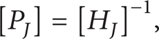

According to [25], P J can be expressed as

where TT, TR, RT, and RR are translational response of force excitement, translational response of moment excitement, rotational response of force excitement, and rotational response of moment excitement, respectively. The superscripts A and B refer to the substructures, and the quantities without superscripts refer to the assembly. The subscripts denote the response and excitement situation. For example, the subscript ja refers to the response of zone “j” under the excitement of zone “a.”
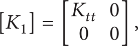
A stiffness matrix with complete spatial degrees can be expressed as

where K tt denotes the translation-to-force stiffness, K tr the translation-to-moment stiffness, K rt the rotation-to-force stiffness, and K rr the rotation-to-moment stiffness.
According to results of [21, 23], the elements K tr and K rt have less effect on the dynamic behavior of the spindle-toolholder assembly. Therefore, K tr and K rt can be neglected for the purpose of improving the calculation efficiency. Some researchers [16] proposed the simplified identification model, as shown in (5), which neglected the rotational FRFs. The model is denoted as joint type I in this paper. However, this simplified model is not suitable for the spindle-toolholder system due to significant influence of RDOF. The adopted model including rotational stiffness is denoted as joint type II, as shown in (6) as
3. RDOF via Finite Difference Technique
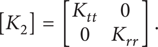
Finite difference technique [27, 28] can be used to estimate rotational quantities by using translational quantities. Three acceleration sensors are deployed on spindle or toolholder, as shown in Figure 2. y A , y B , and y C are the translational displacements of points A, B, and C, respectively. θ A , θ B , and θ C are the rotational displacements of the three points. θ A , θ B , and θ C can be calculated by
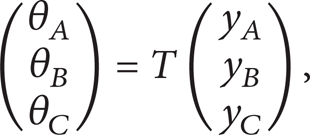
where T is a transformation matrix, can be expressed as

where d denotes a constant spacing of the three points, and has an important influence on the estimation. The smaller the d is, the more accurate the θ A , θ B , θ C will be.

Finite difference schematic diagram and the sensors arrangement.
Dynamic function of the system under excitements can be expressed as
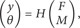
where y, θ, F, and M are in the form of column vectors. They denote translational displacements, rotational displacements, forces, and moments, respectively. Frequency response matrix H is in the form

Here, H yF , H yM , HθF, and HθM are corresponding to TT, TR, RT, and RR quantities in (3).
Equations (7), (9), and (10) can be rearranged to yield

where F and M are irrelevant variables therefore, (11) leads to
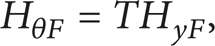
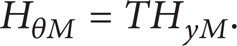
The completed spatial FRF matrix H is a symmetric matrix therefore,

So far, if given the translational FRF H yF , the RDOF FRF HθF, H yM , and HθM can be derived.
Translational FRF matrices are obtained through experiments. However, due to the limit of sensor measurement range, some low and high modes cannot be picked up. This is called “residual problem,” or “modal truncation.” This negative effect will be amplified when performing multiplications or inverse operations shown in (12) and (14). Therefore, it is necessary to conduct residual compensation.
4. Residual Compensation
A complete FRF for typical mechanical joints with small damping ratio can be expressed as
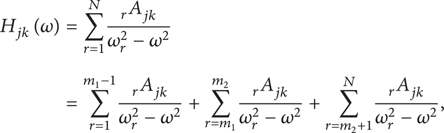
where the subscript j and k refer to the response point and the exciting point, respectively; ω
r
denotes the rth-order natural frequency;
where
A series of points are selected from the experimental obtained FRF curve, which are denoted as (μ1, H jk (μ1)), (μ2, H jk (μ2)) … (μ n , H jk (μ n )). Substituting these points into (15), we obtain

By solving this equation, the modal constants
5. Stiffness Identification and Verification for the Spindle-Toolholder Joint
5.1. Experiment for Translational FRFs
A BT40 type spindle-toolholder experiment system is built up, as shown in Figure 3. In order to exclude the influence of the toolholder-tool joint, a special toolholder with one cylinder end is designed, as shown in Figure 3. The spindle and toolholder are assembled together with a long and lightweight drawbar. One end of the drawbar is screwed and bolted with the toolholder. While the other end of the drawbar is connected with a tension bolt. The tension force of the bolt can be measured by a stress-strain meter, and this tension force transmits through the drawbar to the toolholder. The assembly is suspended to simulate free degree of freedom (DOF) state. In order to acquire experimental data of zone “a” corresponding to Figure 1, a group of sensors is set at the cylinder end of the toolholder, denoted as sensor group 1 in Figure 3. Sensors for zone “b” and zone “j” are located at the outside wall of the taper joint and are denoted as sensor group 2. Each group consists of three piezoelectric acceleration sensors. The sensor type is PCB model 330B30. An impact hammer is adopted for excitement. The exciting locations are set at the opposite location of the sensors, as shown in Figure 3. The signals of the impact hammer and the sensors are collected and analyzed in an LMS modal analyzer.

Spindle-toolholder joint experiment system.
The translational FRFs TT for zone “a,” “b,” and “j” in (3) are obtained by using the right sensors of each group, while the corresponding rotational FRFs TR, RT, and RR can be derived using three translational sensors for each group according to the finite difference theory.
By the hammering test, a series of acceleration FRFs can be obtained by applying 8 kN, 10 kN, 12 kN, and 15 kN drawbar force independently. Figure 4 shows the series curve TT aa , which denotes translational-to-force FRF of the spindle-toolholder assembly. The natural frequencies are listed in Table 1. Comparing the natural frequencies under four different drawbar forces, the forth order is the most sensitive one to the drawbar force change with the highest changing ratio 12.7% [12]. Therefore, the forth order's natural frequency and amplitude value are selected as inputs of proposed model to identify the stiffness of spindle-toolholder joint based on the sensitivity analysis theory. The stiffness of the joint varies with different drawbar forces. However, the identification methods are generally the same. In the following identification and analysis of the joint, the 15 kN drawbar force is adopted to validate the efficiency of the proposed method.
Natural frequencies of the assembly system under four drawbar forces.


The series of FRF TT aa under four different drawbar forces.
5.2. Finite Element Model
In order to verify the stiffness identification efficiency, a finite element model for the spindle-toolholder system is established in ANSYS. The model is shown in Figure 5, and the geometry dimensions are listed in Figure 6 and Table 2. Material density is defined as ρ = 7860 kg/m3, Young's modulus E = 2.0 × 10¹¹ N/m, and Poisson's ratio μ = 0.3. Timoshenko beam element BEAM189 is adopted for both the toolholder and the spindle. In the joint area, the nodes of the toolholder are one-to-one correspondence with these of the spindle and are connected with 52 Matrix27 elements. Matrix27 is an arbitrary elastic element, which can be specified by stiffness matrix. The stiffness values of the 52 Matrix27 elements are assigned uniformly based on the identified results in the next section.
(a) Geometry dimensions of the toolholder, (b) geometry dimensions of the spindle.

Spindle-toolholder system FE model.

(a) Geometry of the toolholder. (b) Geometry of the spindle.
5.3. Stiffness Identification
Rotational FRFs TR aj A , TR jj A , RT ja A , RT jj A , TR bj B , TR jj B , RT jb B , RT jj B , TR ab , and RT bb in (3) can be derived using (12) and (14). Figure 7 shows the amplitude of the derived TR ab , which is the translation-to-moment FRF of the spindle-toolholder assembly. Due to “zero drift” influence of the adopted sensors, the translational FRFs from experiments are distorted near 0 Hz. And the “zero drift” phenomenon will be amplified during deriving rotational FRFs. Therefore, the response range from 375 Hz to 2500 Hz is selected to exclude the influence of “zero drift” phenomenon for the derived TR ab , as shown in Figure 7.

Amplitudes of the derived TR ab .
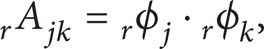
Once the rotational FRFs are calculated, the joint stiffness can be identified using (2) and (3). The forth-order modal parameters are selected to identify the stiffness of spindle-toolholder joint. The forth-order natural frequency and the corresponding stiffness value are shown in Figure 8. The forth-order natural frequency is 1975 Hz, and the identified translational and rotational stiffnesses are K tt = – 6.86 × 10⁷ N/m and K rr = – 2.157 × 10⁵ N · m/rad, respectively.
(a) Dynamic translational stiffness. (b) Dynamic rotational stiffness.
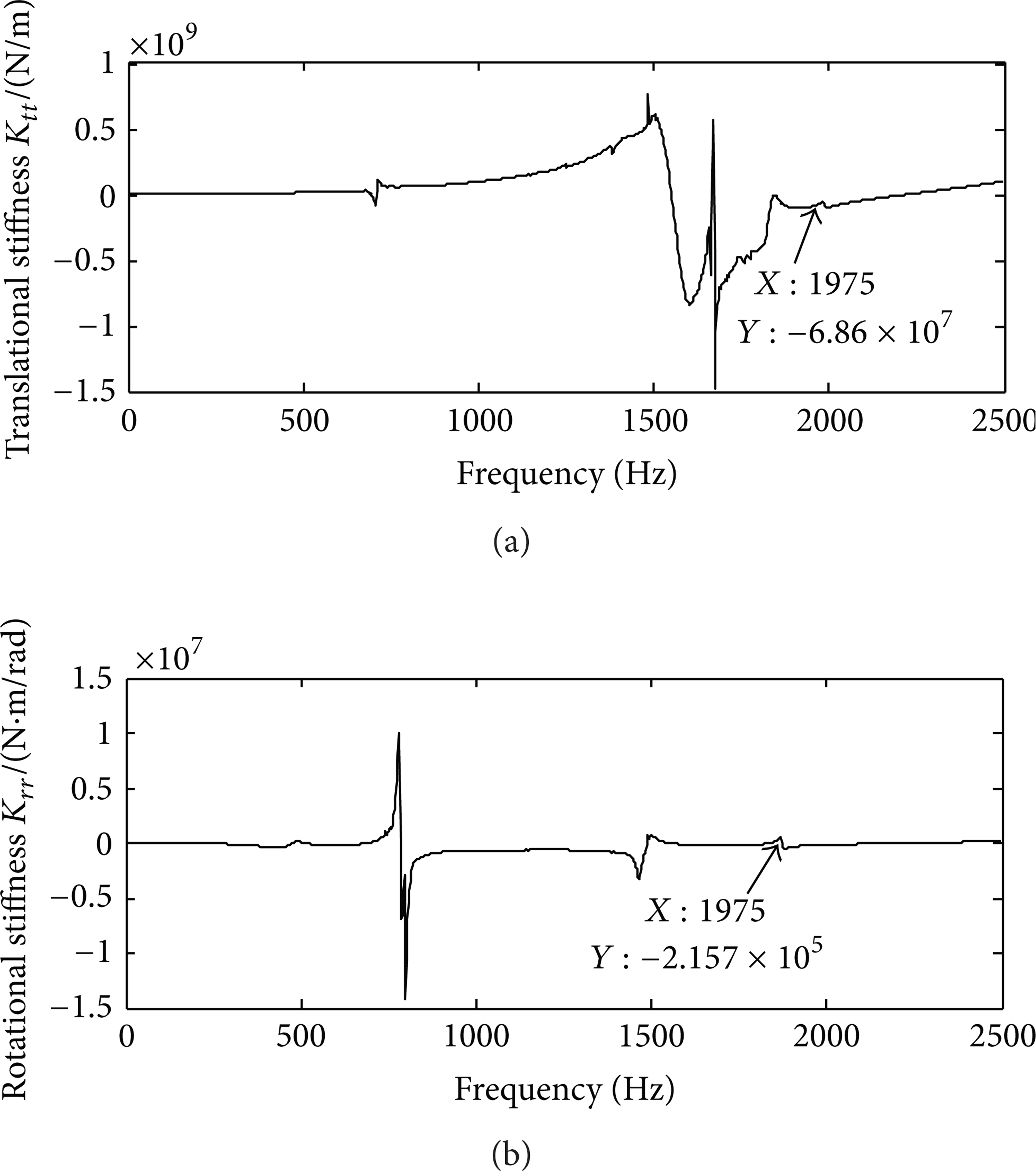
For the purpose of validating the proposed method, a single translational stiffness K tt = – 6.86 × 10⁷ N/m is assigned to the Matrix27 elements for the joint type I, while both the translational stiffness K tt = – 6.86 × 10⁷ N/m and rotational stiffness K rr = – 2.157 × 10⁵ N · m/rad are assigned to the Matrix27 elements for the joint type II. Natural frequencies can be calculated by FE modal simulation as shown in Table 3. Compared with the experiment values, the natural frequencies adopting the joint type I are distorted. The errors of the 1st–3rd order natural frequency are 68.9%, 17.2%, and 7.7%, respectively. Nevertheless, the natural frequencies adopting the joint type II are relatively accurate. The error of the first-order natural frequency is 10.1%, which is much lower than the error of the type I. Although the errors still exist, they have been reduced significantly, as shown in Figure 9. It can be concluded that the joint type I model is invalid and the results with small error can be obtained by adopting the joint type II model. However, a further enhancement has to be developed to meet accurate FE simulation.
Natural frequencies of the joint type I and the type II models.

Error comparison of the joint type I and the type II models.
5.4. Stiffness Identification after FRF Residual Compensation
Due to the range limitation of the adopted acceleration sensor, the “modal truncation” phenomenon will occur during the experiment. And the measurement noises are brought into the measured signals. All of these will affect the identification results. In order to mitigate the effects of “modal truncation” and measurement noises, the residual compensation method is introduced to further enhance identification accuracy of the spindle-toolholder joint. A series of points on the experimental curve are selected, and a new FRF curve can be fitted out based on formula (15). Figure 10 shows the translation-to-force FRF TT aa before and after residual compensation. The regenerated data are much better.

Amplitudes of TT aa before and after residual compensation.
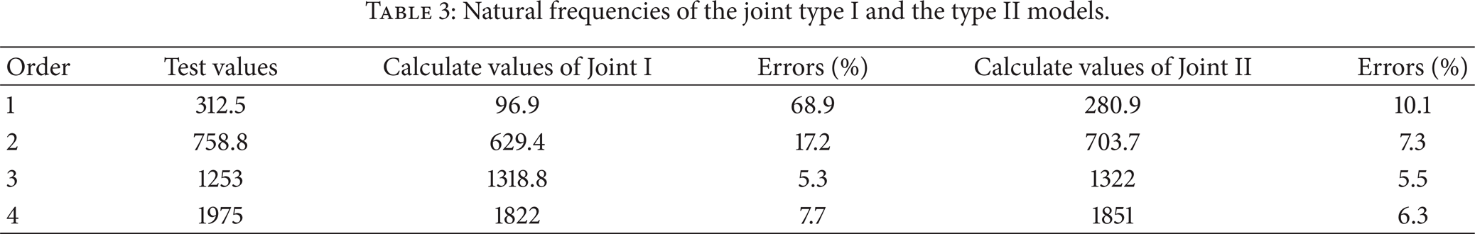
After the FRF curve is regenerated, the joint stiffness can be calculated adopting the regeneration data for the joint type II. The stiffnesses are denoted as K tt ′ and K rr ′, respectively, as shown in Figure 11. The identification results of K tt ′ and K rr ′ are – 6.83 × 10⁷ N/m and – 3.49 × 10⁵ N · m/rad, respectively. The stiffnesses are also assigned to the Matrix27 elements in the FE model as depicted in Section 5.3. The 1st–4th natural frequencies before and after residual compensation are listed in Table 4 and Figure 12. An obviously improvement has been obtained by introducing the residual compensation method. For the first order especially, the error reduces from 10.1% to 0.7%. The maximum error appears at the fourth order with error 6.1%. Therefore, we can conclude that the joint type II model adopting regeneration data is more efficient in the stiffness identification by introducing the residual compensation method. The identification results can meet the requirement of accurately predicting machining stability of spindle system. Simultaneously, structural optimization can be implemented based on the identified stiffness of spindle-toolholder joint in the future.
Natural frequencies of the joint type II model before and after residual compensation.

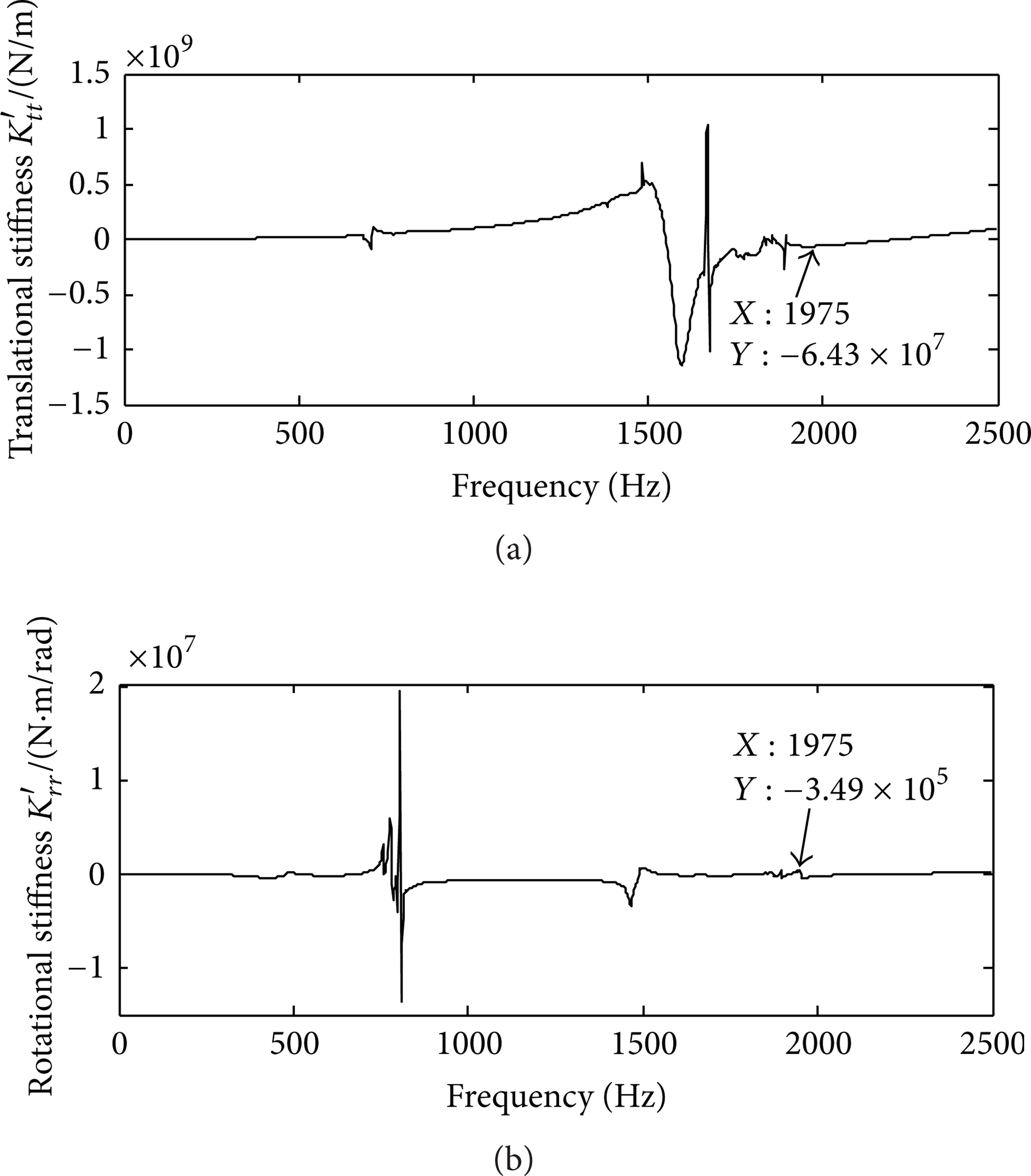
(a) Dynamic translational stiffness after residual compensation. (b) Dynamic rotational stiffness after residual compensation.

Error comparison of the joint type II model before and after residual compensation.
6. Conclusions
In this paper, an enhanced stiffness identification method was proposed for the spindle-toolholder joint. The joint type I and II were established, in which the joint type II include the rotational stiffness. Due to the difficulty of directly measuring the rotational FRFs, the finite difference technique was introduced to estimate the rotational FRFs of spindle-toolholder system. The error of first-order natural frequency for the joint type II was 10.1%, which is much lower than that of the type I. However, the identification result was affected by the “modal truncation” and measurement noises. We introduced the residual compensation method. After the FRF curve was regenerated, the joint stiffness can be calculated by adopting the regeneration data for the joint type II. An obviously improvement has been obtained, in which the error of first order is reduced from 10.1% to 0.7%. Experiment results showed the efficiency of the proposed model in stiffness identification of spindle-toolholder joint.
Footnotes
Acknowledgment
This research is supported by the National Science and Technology Major Project of China (no. 2010zx04012-011).