
Abstract
A new ultrasonic motor using bending modes with single foot is proposed in this study. Two groups of PZT elements are clamped between two horns and two ending caps, respectively, by bolts. Two horns are connected by the driving foot in the middle of the motor. Two orthogonal 3rd bending vibrations of the motor are superimposed and generate elliptical movement at the driving foot. The structure and working principle of the proposed motor are introduced. The structure parameters of the motor are obtained via the ANSYS software. A prototype is fabricated and tested using an impedance analyzer and a scanning laser Doppler vibrometer. The maximum mechanical output force and power of the prototype are measured to be 23 N and 2.9 W, respectively.
1. Introduction
Ultrasonic motors, developed from the 1980s, are new type actuators worked via the converse piezoelectric effect of the PZT elements. They have received profound attentions by their merits of high torque at low speed, compact size, large holding torque without any power consumptions, simple structures, high positioning accuracy, and no electromagnetic radiation [1–4]. They have been a research hotspot of the current mechanical and electrical control field.
From a vibration mode viewpoint, ultrasonic motors can be classified into standing-wave type motors [5–8], traveling-wave type motors [9–15], and composite vibrations type motors [16–27]. For the standing-wave type ultrasonic motors, usually oblique linear movements are produced on the driving tips by flexural vibrations of the stators; they have merits such as simple structure and large output force and disadvantages such as large velocity perturbation and difficulty of bidirectional driving. The traveling-wave type ultrasonic motors show good performance on bidirectional driving, which has been successfully used in cases such as camera autofocus systems. The composite vibrations type ultrasonic motors always have bolt-clamped structures and exhibit larger mechanical output speed and force, and they are becoming the research hotspot of the ultrasonic motor field in recent years.
In 2008, Hu et al. proposed a double-vibrator linear piezoelectric ultrasonic motor [28]. The motor employs two symmetrical bending modes to overcome the modal degeneration problem. But the variational cross-section structure of the motor may impede the transmission of vibration. In 2012, Su et al. designed a modified motor [29], which adopts continuous variational cross-section structure. But the elastic supports of the motor are set at the wave loops of bending vibration shape, the displacement amplitude of which is maximal. The positions of the elastic supports may reduce the bending vibration intensity. Moreover, both two previous motors employ the circular PZT elements. Our previous study indicated that the PZT ceramic away from the neutral plane of the bending mode shape offers more contributions to the bending vibration of the motor under the same exciting voltage, compared with the PZT ceramic that near to the neutral plane [30]. Thus, the square PZT elements are beneficial to increase the displacement amplitude of bending vibration. Based on the previous study, an ultrasonic motor using bending modes with single foot, which belongs to the composite vibrations type, is proposed. In this new design, two orthogonal 3rd bending vibration modes of a bolt-clamped transducer are superimposed to form elliptical movement on the driving foot located at the center of the transducer. The structure and operating principle of the proposed motor are introduced. A prototype motor is fabricated, whose admittance characteristics, vibration characteristics, and mechanical output performance are measured by experiments.
2. Motor Structure
The three-dimensional model of the proposed motor is shown by Figure 1. The structure of the motor contains mostly four parts, which are driving foot, horns, bending PZT elements, and end caps. The driving foot is located at the middle. Two exponential shape horns are in two sides of the foot and connect the foot by their small ends. The driving foot and two horns are an entirety fabricated from a duralumin alloy block by using linear cutting machine. In each side of the driving foot, two groups of bending PZT elements, which contain horizontal bending PZT-A and vertical bending PZT-B, are clamped between horns and end caps, respectively, by the bolts on the end caps. Totally, there are four groups of bending PZT elements in the proposed motor; PZT-A are set at the inner side, while PZT-B are on the outer side. Beryllium bronze sheets as electrodes are clamped between the PZT elements and between the PZT and the horn. In order to fix the motor, there are thin beams and setting holders on the two sides of each end cap. The end cap, the bolt, thin beams, and setting holders are a whole block made from steel. The polarizations of the PZT elements are also shown by Figure 1.

Structure of the proposed motor.
3. Motor Driving Principle
The proposed motor employs four groups of bending PZT elements, which are set orthogonally and named as bending PZT-A and bending PZT-B in Figure 1, to excite the horizontal bending vibration and vertical bending vibration, respectively. The vibration shapes of the two 3rd bending modes are shown by Figure 2. When two alternating voltages with 90 deg phase difference in time are applied on bending PZT-A and PZT-B, respectively, the horizontal and vertical vibrations with 90 deg phase difference in time will be generated in the motor and generate the elliptical motion on the driving foot. The motor is symmetrical in both XZ-plane and YZ-plane, which makes the four outer surfaces of the driving foot have the same motion trajectory and can be used for both linear and rotary driving. Figure 3 shows the operating sequence of the proposed motor in one cycle, while the thin beams and setting holders are overlooked. The deformation sequence of the motor is (1)-(2)-(3)-(4), and anticlockwise elliptical movement is formed on the driving foot, which pushes the runner move right. If the phase difference of two alternating voltages is changed to be −90 deg, the deformation sequence of the motor is (1)-(4)-(3)-(2), and the runner moves toward the left under the clockwise elliptical movement of the driving foot.
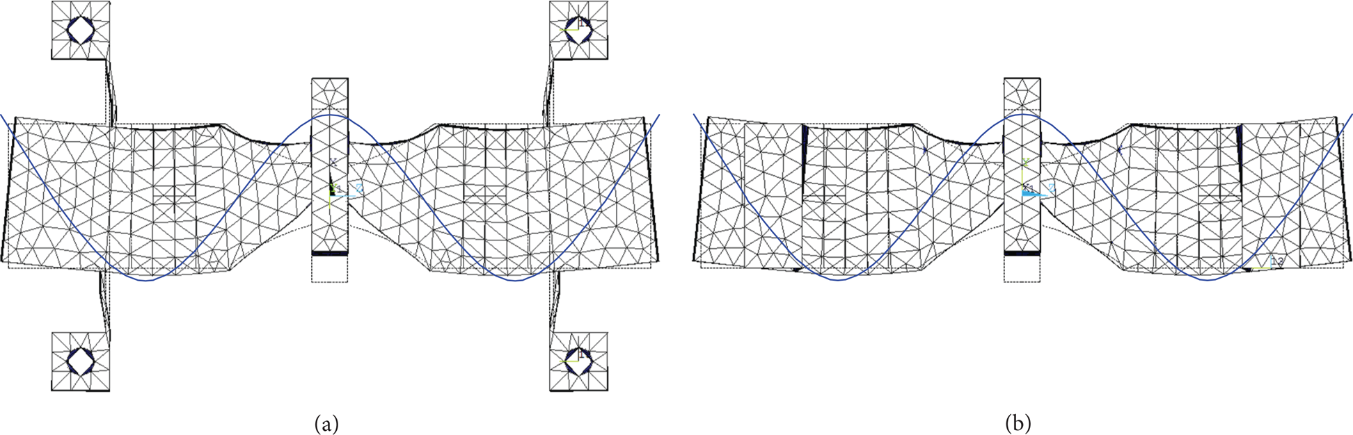
The 3rd bending modes of the proposed motor by modal analysis: (a) horizontal bending vibration, (b) vertical bending vibration.
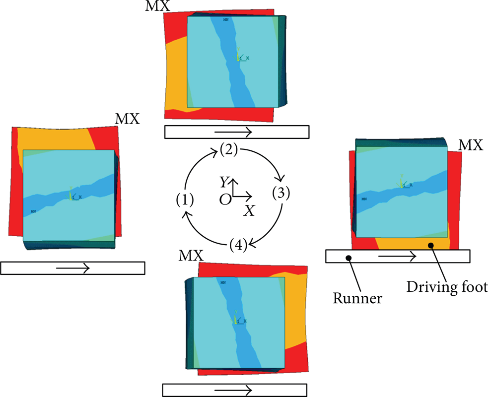
Operation sequence of the proposed motor.
4. The Resonance Frequencies
The proposed motor adopts two orthogonal 3rd bending modes, and its symmetrical structure favors the two vibrations which have the same resonance frequency. To obtain large vibration amplitude and large mechanical output, the bending PZT elements and the driving foot should be set at the wave loops of bending vibration shape. In addition, thin beams and setting holders should affect the vibration modes of the structure as weak as possible. The positions of thin beams and setting holders are near the wave nodes of bending vibration shape. And thin beams which link the setting holders and the main body are set to 9 mm × 20 mm × 0.5 mm via the optimized analysis of ANSYS software. The structure of the motor is optimized by using ANSYS software. Figure 4 lists the final structural parameters of the motor, and the resonance frequencies of the 3rd horizontal and vertical bending modes are 27.05 kHz and 26.95 kHz, respectively.

The final structural parameters of the motor (unit: mm).
5. Experiments
Based on the geometrical parameters listed in Figure 4, a prototype motor was fabricated in order to validate the feasibility of the proposed design, as shown in Figure 5. The weight of the prototype is about 0.25 kg.

The prototype motor.
The admittance characteristics of the prototype motor are measured at low voltage using an impedance analyzer (4294a Agilent). Figure 6 shows the measured admittance and phase characteristics with respect to frequency. The maximum and minimum admittance frequencies of the horizontal bending mode were 26.84 kHz and 27.57 kHz, respectively. The ones of the vertical bending mode were 26.48 kHz and 27.1 kHz, respectively. The series resonance frequencies of the 3rd horizontal and vertical bending modes are 26.84 kHz and 26.48 kHz, respectively, which have a discrepancy of 0.36 kHz.

Admittance and phase characteristics of the motor with respect to the frequency: (a) horizontal bending mode, (b) vertical bending mode.
Only from the admittance test, the vibration modes corresponding with the resonant frequencies cannot be obtained. To have a further observation of the bending vibration modes, a scanning laser Doppler vibrometer (Psv-400-m2, Polytec, Germany) was employed to measure the vibration characteristics of the prototype motor. To test the horizontal bending mode, the side face of the motor is selected as the test region, while the top surface of the motor is selected for the measurement of the vertical bending mode. The vibration mode shapes and vibration velocity response spectrums under bending PZT-A and bending PZT-B excitations are shown in Figure 7. In Figure 7, the horizontal and vertical bending vibration shapes agree well with the 3rd bending mode shapes shown by Figure 2. The resonance frequencies of the 3rd horizontal and vertical bending modes are measured to be 26.492 kHz and 26.109 kHz, respectively, which have a discrepancy of 0.383 kHz.
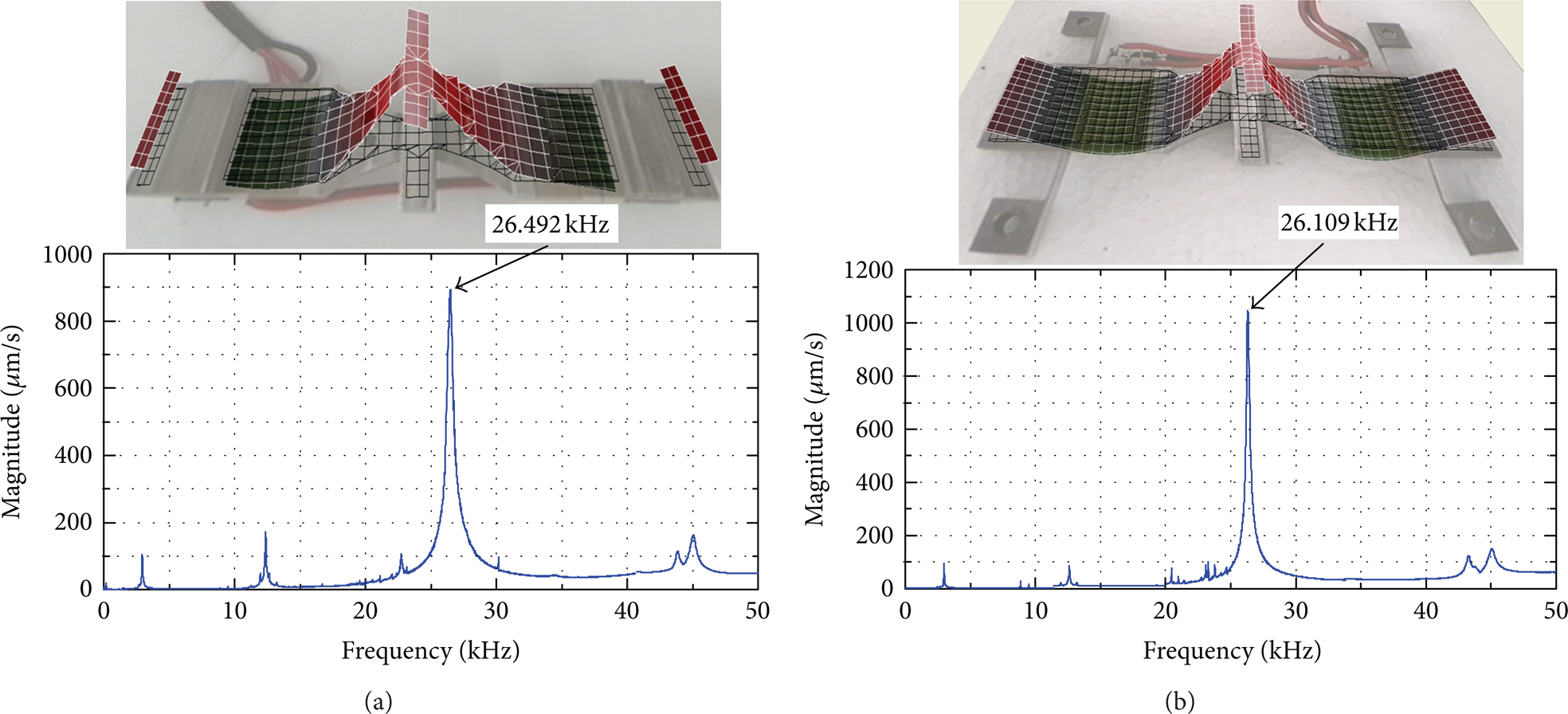
Vibration scanning results of the motor: (a) horizontal bending vibration shape and vibration velocity response spectrum, (b) vertical bending vibration shape and vibration velocity response spectrum.
The mechanical output performance of the prototype motor was tested finally. The motor was set on an experiment platform, in which the driving foot was pressed in contact with a cylindrical rotor. A string and weight system was winded on the rotor via a wheel for the applying of the load, as shown in Figure 8. The rotary speed of the rotor was gained by an encoder firstly and then was transferred to linear one; the output force was gained by the weight. Two alternating voltages with 90 deg phase difference in time were imposed to the PZT elements to accomplish the experiments. Figure 9 shows the speed of the motor versus the exciting frequency, when the voltages (peak-to-peak) are 360 V, the load is zero, and the preload is 50 N. The prototype achieves a maximum speed of 542 mm/s at the frequency of 26.2 kHz.

The experiment setup.

Plot of the speed of the motor versus the frequency.
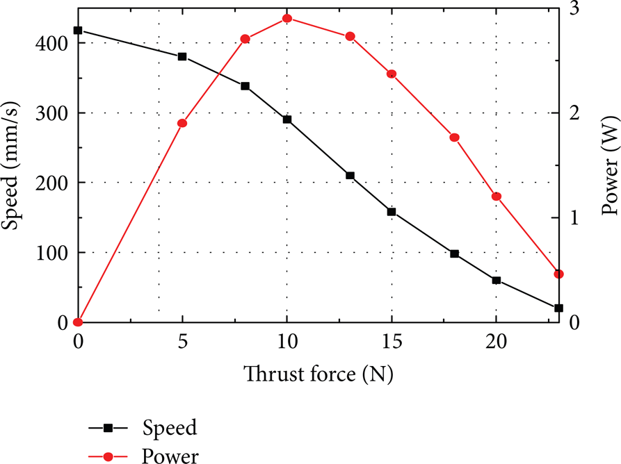
Then, the frequency of the voltages is fixed at 26.2 kHz. When the voltages (peak-to-peak) are 360 V and the preload is 150 N, the plot of the speed and output power versus the thrust force is shown in Figure 10. On this condition, the maximum speed and output force of the motor are measured to be 418 mm/s and 23 N, respectively. And the maximum power of 2.9 W is achieved when the thrust force is 10 N and the speed is 290 mm/s.
Plot of the speed and output power versus the thrust force.
The modified motor designed by Su et al. [29] achieved the maximum speed of 113 mm/s and output force of 10 N. In comparison, the proposed motor has more than 270% of the maximum speed and more than 130% of the maximum output force. This distinct improvement of the mechanical output performance is caused by the following reasons:
the elastic supports of the proposed motor are located near the wave nodes of bending vibration shape. It weakens the affection greatly that the fixed support reduces the bending vibration intensity;
the square PZT elements adopted by the proposed motor can help a lot in improving the displacement amplitude of bending vibration;
the horn of the proposed motor is exponential shape, which is in favor of amplifying the vibration amplitude and velocity of the driving foot.
6. Conclusion
A new ultrasonic motor using bending modes with single foot was proposed, studied, and tested. The present motor adopts the superimposing of two orthogonal 3rd bending vibration modes to generate elliptical motion at the driving foot. When two alternating voltages with 90 deg phase difference in time are imposed to the PZT elements, the motor can drive the runner. The feasibility of the designed motor is verified by means of the admittance and vibration tests. The prototype achieves a maximum mechanical output force of 23 N and a maximum power of 2.9 W.
Conflict of Interests
The authors declared that they have no conflict of interests to this work.
Footnotes
Acknowledgments
This project is supported by the National Natural Science Foundation of China (no. 51105097 and no. 51075082), the Self-Planned Task of State Key Laboratory of Robotics and Systems (HIT no. SKLRS201302B), and the China Postdoctoral Science Foundation (no. 2012M510940).