
Abstract
With the rapid development of the smartphone market, future cars seem to have more connections with intelligent cell phone and Internet. Intelligent transportation system (ITS) and telematics system have become research focus in recent years. There is an increasing demand for remote monitoring and diagnostic system as the further research of hybrid electric vehicle (HEV) goes on. In this paper, a remote controller area network bus (CAN-Bus) data monitor and diagnostic system for HEV is presented using on board diagnostic version-II (OBD-II) and Android-based smartphone. It is low-cost, convenient, and extensible with smartphone used in the system to realize communication with ELM327 and remote monitoring center wirelessly. The prototype of client and server is developed in Java language, and it is proved by the test that the system works stably and the collected data have practical values.
1. Introduction
In the past decades, as environmental protection and energy saving have been greatly concerned, automobile manufacturers and well-known universities are active to research and develop new technologies to improve fuel efficiency, in which hybrid electric vehicles (HEVs) have been adopted as a commercial technology. Nowadays, various HEV topologies have been developed, such as parallel HEVs, series HEVs, and power-split HEVs [1–6].
As HEVs become increasingly popular, the demand for HEVs remote monitoring systems is growing [6–10]. First, there are more than two power units (engine and motors) installed in the same vehicle. In order to improve fuel efficiency of the vehicle, an optimized energy management control strategy must be used [1–5]. Then a remote monitoring system is needed to provide the running parameters of the HEV. Second, in order to improve efficiency of transportation, an intelligent transportation system and an on-board telematics system are needed to share the information in vehicles and remote service center [11–16]. Third, taking the public transportation into consideration, it is very important to improve the traffic safety by monitoring the running status and performance parameters of hybird buses and taxies in real time. These tasks can be quickly realized by online diagnosis and troubleshooting based on remote monitoring and diagnostic system [17–21].
Much research about remote monitoring system has been carried out. With a digital signal processor (DSP) used as a central processor, Fang et al. designed an on-board data acquisition system of hybrid electric vehicle [9]. Aljaafreh et al. designed a system based on wireless networking technology (WiFi), in which, without a base station to upload the collected data to a web server, the data acquisition system is placed onboard, together with database server and web interface for fleet management automation [22]. Kucera et al. developed a vehicle data acquisition system to reduce hazardous situations on the roads by analyzing driver and identifying the degradation of driver's abilities [23]. Dow et al. developed a dedicated short-range communications (DSRC) vehicular warning and notification system. It was capable of detecting road hazards and transmitting traffic information to the Internet through intervehicular communications via DSRC [24]. Montazeri-Gh and Asadi designed a vehicle telematics system to receive traffic data and also built a genetic-fuzzy controller that considered the influence of traffic condition on the controller parameters. The traffic data received from the telematics system was used to tune the proposed intelligent controller [25]. Lin et al. developed a vehicle online diagnosis and real-time early warning system to acquire OBD signals that is transmitted to a Server of Maintenance Center via General Packet Radio Service (GPRS) mobile communication for immediate actions [26].
However, the proposed solutions and systems need external dedicated hardware, network, or specialized software. Moreover, most of them are running on a desktop, and the associated high costs restrict their development and promotion.
With the rapid development of smartphones, its hardware configurations are becoming increasingly powerful, and its applications tend to be diversified. Nowadays, smartphone is widely used around the world, and it can also be used as controller/multimedia/data collector/mobile localizer except for mobile phone [11, 12, 27–32]. With the development of ITS and ecological electric vehicle, to develop a vehicle remote monitoring system is of great significance. In this paper, a HEVs CAN-Bus data monitor and diagnostic system based on OBD-II and Android-based smartphones is presented. It is low-cost, convenient, and practicable to use smartphones in the system to implement communication with ELM327 and remote monitoring center wirelessly. There are two key problems that need to be solved: (1) how to program to acquire vehicle real-time status information on Android platform; (2) how to integrate different functions such as vehicle positioning, route tracking, user chatting, and information sharing.
2. System Structure
2.1. Powertrain Structure of HEV
Since Toyota Hybrid System (THS) was equipped on Prius in 1997, the electric variable transmission (EVT) had been widely accepted with its good performance in fuel consumption and emission. After Changan New Energy Automobile (CNEA) Co. finished their Integrated Starter and Generator (ISG) HEV project, the ISG HEV appeared in the market. In order to obtain better fuel efficiency, CNEA started a new EVT HEV project.
A single motor speed coupling hybrid system has been developed; the structure of the powertrain is shown in Figure 1. The powertrain configuration of the HEV includes an internal combustion engine, a One Way Clutch (OWC), a multi-disc wet clutch, a planetary gearset (PGS), an ISG motor, an automatic mechanical transmission (AMT), and NiMH-battery [33–35]. The PSG has a sun gear, a carrier with planetary gears, and a ring gear. The sun gear and the ring gear are the input elements. The sun gear is connected to the motor and the ring gear is connected to the engine shaft. The carrier is the output element and is connected to the input shaft of the transmission. The OWC and the multi-disc wet clutch inner part are mounted to the engine shaft. In this way, the OWC allows the engine to rotate forwards freely and prevents the engine from rotating backward. The multi-disc wet clutch is disengaged when it is in electric drive mode; when multi-disc is engaged, it will help to start the engine with motor or to lock the PGS. The ISG motor is used to assist the engine or to recover braking power. The AMT is used to expand the speed ratio of the system. It also can change the rotating direction of the output shaft to fulfill the reverse function of the vehicle.

Powertrain structure of ISG speed coupling hybrid system.
The powertrain system has the following work modes: pure electric driving, power boosting, regenerative braking, normal engine driving, electric variable transmission, and so forth. The driving modes are listed in Table 1; the red lines in Figure 2 show the power flows of different driving modes. In order to acquire the source data to optimize the control strategy, a remote monitoring and diagnostic system is developed through ELM327 and Android-based smartphones.
Driving modes of ISG speed coupling HEV.

✓: clutch engaged; ✗: clutch disengaged.

Power flows of the driving modes.
2.2. System Structure
Telematics is a compound word of Telecommunications and informatics; it is an integrated information service system. It provides traffic information, emergency response strategy, remote vehicle diagnosis, and internet services to both driver and passengers by integrating GPS, wireless voice, digital communication, and satellite navigation [11, 12, 24–27, 36–39]. Telematics system is also known as Internet of Vehicles (IOV) in a narrow sense, and it makes up an important part of ITS. The HEV CAN-Bus data monitor and diagnostic system proposed in this paper can be seen as a simplified telematics system.
The system presented in this paper consists of HEV, ELM327, an Android smartphone, and a remote monitoring center; the system structure is shown in Figure 3. ELM327 interacts with the HEV through OBD-II interface, the Android smartphone is used as the client to complete data acquisition and data transmission, and the remote monitoring center realizes data reception and real-time monitoring.

System structure.
3. Technical Details
There were two hardware solutions to perform vehicle data acquisition, accident warning, trouble diagnosis, and remote monitoring: (1) embedded system with CAN interface or OBD port, GPS module, and wireless communication module; (2) take advantage of smartphone, ELM327 or OBDLink and Bluetooth technology. Furmanczyk et al. designed the Vyatta hardware device which consisted of an ELM327 to interface with the OBD port, an ATmega644 microcontroller to facilitate communication, and a Bluetooth module to interface with the smart phone [31]. Lin et al. proposed the on-board computer of the remote online diagnostic system, which was mainly comprised of OBD-II to RS232 adapter, GPS receiver, encoder, 3G module, and so forth [28]. Lin et al. developed the G3 client hardware using an ARM CPU, a GPS module for positioning data, and a GPRS module for mobile communication [26]. Al-Taee et al. presented a distributed system for remote monitoring of vehicle diagnostics and geographical position by using On-Board Smart Box (OBSB); it was installed inside the vehicle and equipped with an integrated GPS receiver and a GPRS communication module [13]. Cabala and Gamec analyzed vehicle communication through diagnostic interface OBDII and designed and implemented an application on Android system, which can obtain real-time data from ECU [19]. Tahat et al. provided a vehicle diagnostic and tracking system utilizing OBD and Bluetooth [21].
Compared with the first solution, the second solution is low-cost, easy to operate, and more convenient. Consider that ELM327 equips OBD interface and Bluetooth module as shown in Figure 4; smartphone integrates GPS and GPRS/3G; the second solution is adopted in this paper. We cannot only collect the location information, running parameters, and trouble codes, but also interact with other cars and remote server.
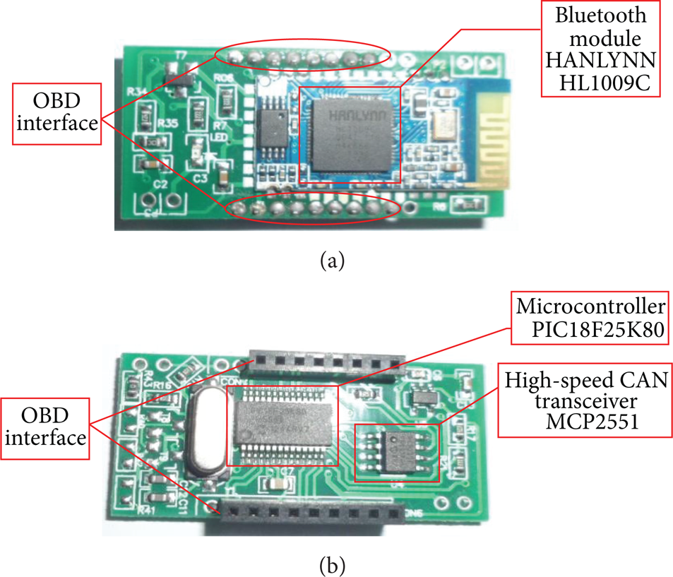
The internal circuit of ELM327.
3.1. OBD System
On-Board Diagnostics (OBD) is a computer-based system originally designed to reduce emissions by monitoring the performance of major components such as the engine, catalytic converter, particulate filter, oxygen sensor, emission control system, fuel system, and exhaust gas recirculation (EGR). Its schematic diagram is shown in Figure 5. A basic OBD system consists of an ECU, which uses input signals from various sensors to control the actuators to get the desired performance [28, 31]. The “Check Engine Light,” also known as the malfunction indicator lamp (MIL), provides an early warning of malfunctions to the driver. A modern vehicle supports hundreds of parameters, which can be accessed via the diagnostic link connector (DLC) by using external diagnostic devices.

Schematic diagram of OBD system.
In this paper, ELM327 is used to connect with OBD-II interface and convert the OBD signals into series signals, which are used to communicate with the upper machine. OBD-II interface has sixteen pins as shown in Figure 6. The OBD communication protocol differs from automobile manufacturers in that it includes ISO 9141-2, ISO 14230-4 (KWP2000), ISO 15765-4 (CAN), SAE J1850 PWM, and SAE J1850 VPM [40, 41]. Which protocol the vehicle uses can be determined by pin connections; the corresponding relation is shown in Table 2.
The corresponding relation of pin connection and OBD protocol.
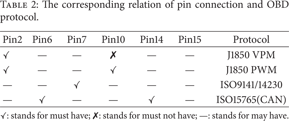
✓: stands for must have; ✗: stands for must not have; —: stands for may have.

OBD-II interface.
3.2. GPS and Network Communication
Global Positioning System (GPS) is convenient and practical and allows the vehicle to be positioned and navigated on a global scale by using GPS positioning satellite [13, 15]. Assisted GPS (A-GPS) is a technology combining network base station and GPS information; it is widely used on the smartphone to improve positioning accuracy and shorten positioning time. With the rapid development of network technology, GPRS/3G has been widely used and 4G network has also entered trial period. So mobile network can be used to ensure the efficiency of data transmission.
3.3. Data Transmission
The open source project HttpClient is utilized in this paper to complete the communication between Android client and Web server. After the client, based on Hyper Text Transfer Protocol (HTTP), sends request to the server each time, the server will return response messages (including the request is correct or not and the requested data) to the client. The server will shut down the network connection after the client has received the response messages.
3.4. Data Storage
Key-value table is used as data transmission format between client and server; the acquired data are stored on the server via SQL Sever2005, which also used to complete the management of driver information and vehicle information.
4. System Design and Implementation
The main function of the proposed system is wireless data acquisition and transmission of HEV operation parameters. Considering the demand for rapid vehicle positioning, the vehicle positioning and trajectory tracking function are added [15, 21]. The system is developed with Client/Server (C/S) mode, the Android application acts as a client, and the Web application acts as a server. Modular programming is adopted in the development process; the system will be integrated and completed after the basic function modules of client and server are built.
4.1. Vehicle Positioning and Trajectory Tracking
Android Software Development Kit (SDK) contains basic location Application Programming Interface (API) which interacts with GPS hardware [42]; the API and Baidu map are used to accomplish vehicle positioning in this paper; the flowchart is shown in Figure 7.

The flowchart of vehicle positioning.
In order to embed Baidu map in the application, we first need to apply for a Baidu map API key, then finish the project configuration, and finally execute according to the following steps:
add internet access permission and positioning function usage permission in the file AndroidManifest.xml,
create layout for activity, and add widgets in the layout file to show Baidu map,
create activities, initialize the map, set the zoom level, and add the function button,
program to realize the function.
We can complete the related operation by adding buttons on the MapView. When the “Location” button is triggered, we can obtain the longitude and latitude of current position and display it by the way of Toast. When the “Track” button is triggered, we can start tracking with the current position as the starting point, then draw the route on the map with the change of location information; the ending point will be drawn until the “Stop” button is clicked.
4.2. Vehicle State Information Collection
ELM327 communicates with ECUs via OBD protocol; ELM327 can be set by AT commands and the real-time data are acquired by OBD commands. A kind of format named “Mode plus Parameter Identification (PID)” is used as OBD command; the nine diagnostic modes and all PIDs are described in detail in international standard such as SAE J1979 and ISO 15031-5. The diagnostic modes defined in ISO 9141-2, ISO 14230-4, and SAE J1850 are slightly different from ISO 15765-4 [40, 41]. In this paper, data such as engine Revolutions Per Minute (RPM), engine load, throttle position, mass air flow (MAF), diagnostic trouble code (DTC), and vehicle speed, can be obtained. The relative OBD commands are listed in Table 3.
OBD commands and its description.

ELM327 connects with the car through OBD-II, and smartphone connects with ELM327 via Bluetooth. Smartphone sends OBD commands and reads the response; the data flow of whole process is shown in Figure 8. The programming method is as follows: ObdCommand class is created as a parent class according to SAE J1979, and other child classes which are defined to acquire specific data inherit the parent class. After the successful connection of Bluetooth, it will always work as a background service. The queue technology is adopted in the process of data acquisition and a buffer is used to store data temporarily.

Data flow of data acquisition.
The flowchart of data acquisition is shown in Figure 9.

The flowchart of data acquisition.
4.3. Data Transmission
After the location information and vehicle state information are collected successfully, the data will be transmitted to the remote server. When the menu “Upload data” is clicked, data are submitted to the specified server by means of POST, and the request of POST is sent through HttpClient.
5. System Testing
5.1. Vehicle Positioning Test
After acquiring the latitude and longitude information through GPS embedded in the smartphone, the position of the vehicle is monitored on the Baidu map. A Samsung S5660 is used in this test; it can be seen from Figure 10 that the vehicle location is accurate and the moving route is clear.

Vehicle positioning.
5.2. Data Acquisition Test
ELM327 communicates with ECU via CAN protocol with 29 bits ID and 500 kbaud transmission rate. The Android smartphone connects with ELM327 via Bluetooth; it works at 2.45 GHz, and its highest transmission speed can only reach 63.1 kb/s in real tests [36–38]. The real-time running parameters can be acquired by smartphone after being connected with ELM327 successfully. The data acquisition and system configuration screens are shown in Figure 11.

Data display and system configuration.
The data as shown in the left figure are (in order from left to right) mass air flow, engine load, throttle position, compass in the first row; engine rpm, speed, and fuel economy in the second row; ambient air temperature, air intake temperature, and engine coolant temperature in the third row; barometric pressure, intake manifold pressure, fuel pressure, and timing advance in the fourth row.
5.3. Remote Monitoring Test
The HTTP protocol is used to transmit data between the client and server. The user interface of remote monitoring is shown in Figure 12.

Remote monitoring screen.
Android client and the web server are programmed in Java. With the information uploaded by Android client, we have implemented real-time monitoring and track playback on the web server. What is more, the warning signal will be displayed if DTCs are detected. Take engine RPM and vehicle speed, for example, the data changes over time as shown in Figure 13.

The data charts.
6. Conclusions
This paper presents a prototype of Hybrid Electric Vehicles CAN-Bus data monitor and diagnostic system via OBD-II and Android-based smartphones. The ISG speed coupling HEV is designed and put into use successfully; we take a Samsung S5660 and a Changan ISG HEV as the experimental tools in this research. 3G mobile network, GPS, OBD, and Bluetooth are integrated to develop this system. It is shown in the test that the system can correctly acquire the running parameters and the location information of HEV and transmit them to the remote web server for monitoring. The developed system provides an applicable solution for vehicle information acquisition and remote monitoring based on the Android platform.
In the future, it is worth developing more powerful functions such as data analysis and processing and information sharing on the smartphone with the lightweight database SQLite. It's also worth improving the ability of the server to monitor more information such as real-time traffic conditions, road conditions, and accident scenes. In the end, the system regarded as a node of telematics system needs to be researched in depth.
Conflict of Interests
The authors declare that there is no conflict of interests regarding the publication of this paper.
Footnotes
Acknowledgment
The authors acknowledge the support of the National Natural Science Foundation of China (Project no. 51075411). All of the work was supported by the project.