
Abstract
This paper presents a method to enhance computational efficiency of the nonlinear dynamic analysis of the large-scale deep-hole drilling machine. Based on finite element model, the drilling shaft system is constructed into Timoshenko beam element on the basis of flexible rotary shaft so as to increase the accuracy of numerical calculation. In order to save the calculation time and resources, modal synthesis technique is adopted to reduce the feature modal of linear freedom degrees of drilling shaft system. As a result, the accuracy required by the non-linear analysis will not be loss. On the basis of these, the whirling characteristics of drilling shaft system are studied under the conditions of different shaft lengths, and simultaneously, the stability patterns of drilling shaft motion and its stability region are obtained in the selected drilling depth and cutting speed parameters while drilling intersection holes.
1. Introduction
In modern manufacturing field, there are a great number of deep-hole manufacturing parts, such as the screw boot holes of steam turbine, slanted wall holes of aero-spacecraft pressures regulator, and cooler intersection holes. They are in general the basic manufacturing parts for the transmission of dynamic force and energy conversion, whose qualities can have the direct effect upon the performances of the relevant products. Nevertheless, how to calculate the dynamic behaviors problems of drilling tool system efficiently and accurately still remains unsolved due to the complexity of drilling mechanism, the diversity of machining conditions, and the randomness of drilling shaft rotational states.
In recent years, the scholars have carried out much research work on the dynamic stability solution and prediction of deep-hole machining tools. Al-Wedyan et al. maintained the continuity of the original system by introducing homogeneous boundary condition in local points to analyze the drilling shaft system model and discussed the whirling motion behaviors of the single-span deep-hole machining drilling shaft system [1]. Messaoud and Weihs obtained the revised dynamic model of BTA deep-hole machining drilling tool system via the computer to collect the vibration signals of drilling tool system and in combination with the analysis theory of mathematical statistics [2]. The above-mentioned methods use the local dynamics properties of deep-hole machining drilling shaft system and also adopt the direct analysis or mathematical statistics methods to investigate the dynamic characteristics of drilling shaft in time-varying drilling system. However, in their drilling shaft system model, the actual existing mass eccentricities of drilling shaft system and the influence of nonlinear cutting fluid forces cannot be taken into account. In deep-hole machining, although the nonlinear cutting fluid forces and cutting forces act upon the drilling tool system locally, their influencing effects are global because of their coupling with each other.
Chin et al. established the lateral vibration equation of rotary drilling shaft in terms of the Timoshenko beam or Euler-Bernoulli beam, respectively, in which the effects of cutting fluid and cutting forces are taken into account, and the model is used to study the drilling shaft vibration model and natural frequency [3–5]. In 2005, Hu et al. assumed that deep-hole drilling shaft was a rigid drilling shaft model to analyze the whirling problem of rotary drilling shaft caused by existing cutting fluid between the drilling shaft and hole wall and first suggested the cutting fluid reaction forces with the nonlinear form. Then, they studied the mechanics mechanism of drilling shaft whirling motion and unstability due to the cutting fluid perturbation [6]. Nevertheless, as far as the dynamic problem of drilling shaft system is concerned, the above-mentioned researches have simplified the drilling shaft system as the total infinite length or a second order axis with static fluid so as to obtain an analytical expression for the cutting fluid forces. In such a way, some dynamics behaviors of the system will be unavoidable to lose. In order to make up the shortages in this aspect, Kong et al. adopted the lumped quality method to establish the finite length drilling shaft model to study the stability and bifurcation of drilling tool system. In the model, the drilling shaft mass eccentricities and cutting forces impact are taken into full account. The variational constraint principle is introduced to make the fluid forces necessary for nonlinear analysis, and Jacobian's metric calculation can be completed at the same time, and also, the correlative experiments are used to test the feasibility of the method, but the shear deformation and rotary inertia impact of the drilling shaft cannot be considered [7]. Generally speaking, the above-mentioned researches have simplified the drilling shaft into beams or axis models with the extreme few freedom degrees, and there exist gaps with the actual conditions. In practice, the drilling shaft system is a continuum with more parts and has one or two auxiliary supports. For this reason, it is difficult to describe the drilling shaft system with a simple system model.
In the actual deep-hole machining, drilling shaft system is subject to the multifactors' actions such as the auxiliary supports, the cutting fluid forces, and the fluctuation of cutting forces. Accordingly, it is a typical high-dimension, local nonlinear dynamic system. However, if we do this in such a way, there can be no doubt that the dimension numbers of the system can be raised and that the difficulty of finding solutions will be increased. Thus, whether the order numbers of the system can be reduced or not, the local nonlinear dynamic features of drilling shaft system can be maintained to satisfy the accuracy requirement in calculation, whereby research on dynamic features and stability laws of the drilling tool system will become the key problem at present.
With an aim at the above-mentioned problems and based on the freeinterface modal synthesis technology, this paper suggests a kind of system freedom shrinkage method. By shrinking higher-order linear freedom degrees and remaining the nonlinear freedom degrees of drilling shaft system, the numerical errors caused by the coordinate transformation will reduce, whereby making the reduced order drilling shaft system keep the local nonlinear features. In addition, the local cutting forces, the nonlinear cutting fluid forces, and the imbalance forces borne by the drilling shaft are easy to be incorporated into the shrunken system equation, and then, the reduced order model and the whole freedom-degree drilling shaft model (i.e., the original system model without reduced order of drilling shaft system) are adopted in the computation, respectively, so as to obtain the drilling shaft periodic rotational trajectory, and the contrast results indicate the accurateness of this method. With the practical large size deep-hole machining as the analytical objective, this paper deals with the whirling principle of drilling shaft system under the conditions of different shaft lengths. Further, according to the machining features of intersection holes, the unstability and stability regions of the drilling shaft motion can be obtained in the drilling depth and cutting speed parameters space. Meanwhile, a great quantity of numerical calculation results have proved the stability and feasibility of this method.
2. Mathematical Modeling of Drilling Shaft System
The cutting mechanism of deep-hole drilling is to install the specially configured cutting tool on the round hollow drilling shaft so as to make the tool do the rotary motion opposite to the workpiece at a high speed. The cutting tool can be cooled or lubricated by the high-pressure cutting fluid injecting into the cutting region, and simultaneously, the cutting chip is ejected from the tool shaft inner hole. So, it is a kind of the inner ejection deep-hole cutting machining method.
To ensure the scheme accuracy, the drilling shaft system in this paper is modeled on the basis of [7], where the nonlinear vibration behaviors of drilling shaft was investigated when considering the imbalance forces of drilling shaft, cutting forces fluctuation, and nonlinear cutting fluid forces, and the numerical results was confirmed by the experiments. So, the deep-hole drilling shaft system model with the multiauxiliary supports is established as shown in Figure 1.

Schematic diagram of deep-hole drilling for nonrotary workpiece.
In Figure 1,l, l c , l sa , and l sb are the drilling shaft length, the machining depth, the positions of auxiliary support A, and auxiliary support B respectively. F cx , F cy , F x , and F y , are respectively, the cutting force fluctuation and cutting fluid force components of drilling shaft on the x and y negative directions, and ω is the drilling shaft rotary speed.
In order to make the drilling shaft the system model be closer to actual drilling shaft, Timoshenko beam finite element model is adopted to account the influences of the drilling shaft gyroscopic effect, rotary inertia, and shear deformation. In accordance with the deep-hole machining flexibility rotary drilling shaft system model established in Figure 1, the drilling shaft is simplified into the multispan flexible rotary shaft structures, and the workpiece is fixed on the drilling shaft end. The auxiliary support is simplified into the movable simply support, and the drilling shaft is dispersed into n – 1 units along the z direction so that the whole drilling shaft can have more n-nodes, as shown in Figure 2.

The model of flexible-rotating drilling shaft system.
In Figure 2, x
i
, y
i
, and ψ
i
, φ
i
(i = 1, 2, …, n) are the lateral translations and rotation angles of ith nodal point along the horizontal and vertical directions, respectively. Therefore, drilling shaft system boundary condition can be defined as in the spindle box end
Based on the Timoshenko beam model, the drilling shaft system dynamics equation can be written as follows:

where
As to the local nonlinear of multi-span flexible drilling system, the dynamic equation (1) of drilling shaft system can be rearranged in terms of its linear freedom degrees and nonlinear freedom degrees as follows:

where
In terms of this block rule and in combining with the mode synthesis technology of freedom interface model, the linear feature model can be truncated so as to shrink the freedom degrees, whereas the nonlinear freedom degrees are still maintaining in the physical space. In considering each substructure interface freedom degree without the constraint model applied, several low-order models are retained after the dominating modes of each substructure is obtained. At the same time, the residual models of each substructure are used to compensate the influence of truncated high-order dominating modes. If the substructures have had the rigid displacement, attachment modes will be released by using residue inertia in residual flexible matrix to compensate the truncated predominant modes with high orders so as to raise the accuracy and save the calculation resources.
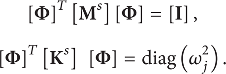
In considering the interface with complete free, the free vibration equation of formula (2) can be as follows:

In order to obtain the characteristic modes of (3), it can be converted into the state space. Research results obtained by Al-Wedyan et al. and Weinert et al. indicate that the drilling shaft system model has had enough accuracy when the damping effects are not considered [1, 8]. Nevertheless, as to the gyroscopic matrix in the drilling shaft model, the modal analysis cannot be neglected because of gyroscopic matrix closely related to cutting rotary speed. In order to be convenient for the calculation, it is necessary to adopt the real eigenvalues problem with the generalized undamped vibration as follows:

where
As to (2), the freedom degrees in linear part can be shrunk,

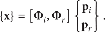
In (6) and (7),

In (8), the diagonal matrix [


In (9),

In (11), g and k express the degrees of freedom caused by rigid displacement and nonrigid displacement in the interface freedom degree, respectively; a expresses the rest of degrees of freedom, which do not include the interface freedom. For this reason, (7) can be written as follows:
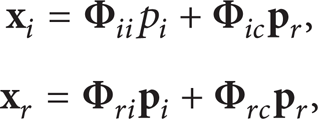
where Φ ii ∈ Rn i × n i , Φ ic ∈ Rn i × n c , Φ ri ∈ Rn r × n i , and Φ rc ∈ Rn r × n c .
From (12), we can obtain the following:
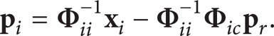
Therefore, the whole transformation can be obtained as follows:

Namely,

where
Applying the transformed equation (14), the equation of shrunken parts can be expressed as follows:

It can be seen from the contrast of (1) with (16) that, owing to n i ≪ n r and n c ≪ n r , the number of (1) is sharply reduced from the original n (n = n i + n r ) to the number of (16) m (m = n i + n c ). In addition, it can be seen from (15) that the nonlinear degrees of freedom are completely retained in the physical space so that there is no need to carry out the coordinate transformation, whereby saving the calculation resource and avoiding numerical errors to be caused by the coordinate transformation.
After the shrinkage, it is very easy for the local external excitation, such as the cutting forces fluctuation and the nonlinear cutting fluid forces, to incorporate into the shrunken system equation. The shrunken dynamic system equation can be obtained from (16) in the following:

where
By introducing the state variable

3. Nonlinear Periodic Responses and Method of Periodic Solutions
When the lathe design parameters and machining conditions are determined, it is necessary to obtain the tool's accurate rotational trajectory and its stability. This paper adopts the shooting method and Floquet theory to compute the periodic trajectory solution of drilling tool and its stability. If the tool rotary state is the stable periodic trajectory, the following conditions must be satisfied:

where

where
From (18), there will be

In (21),
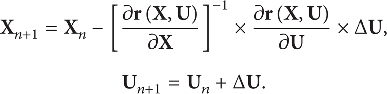
Subsequently, the shooting method is used to modify the periodic solution when the system parameters set is
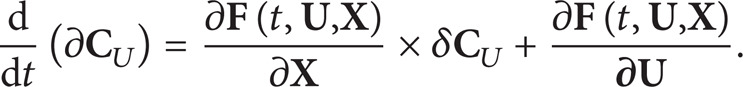
In (23), ∂
4. Method Tests
In order to test the effectiveness of the above method, the program compiled by the above algorithm is used to carry out the calculation of the dynamic behavior of drilling shaft system. The substructure method with freeinterface is adopted to classify the drilling shaft system into 8-unit substructures, as shown in Figure 2(a). The correlative calculation parameters are as follows: the drilling shaft length is l = 4 m; the external diameter of drilling shaft is 26 mm; the inner diameter of drilling shaft is 19 mm; the hole diameter is 28 mm; the drilling depth is l
c
= 427 mm; the positions of auxiliary supports A and B are
Figure 3 is the drilling shaft nodal periodic trajectories obtained via the calculation by adopting the whole freedom degree drilling shaft model and the shrinkage model (the reduced-order model with retaining 12-eigenmodes modal), respectively. When rotary speed is ω = 905 r/min, the trajectory mapped with the dot “·” is calculated from the reduced-order model with retaining 12-eigenmodes model, whereas the other is the trajectory mapped with the dash “—” in the whole freedom degree model. It can be seen from the calculated results that the trajectories from the different models of two types are approximately the same. Furthermore, Table 1 lists the iterative errors of drilling shaft trajectory by using the improved shooting method in the reduced-order model or the whole freedom degree model. It can be seen from Table 1 that the adoption of reduced-order model to obtain the periodic response of drilling shaft system only needs 5-step iterative process, and the accuracy requirement (ε ≤ 10−6) is satisfied. Thus, the above results indicate that the shrunken model of drilling shaft system is adaptable to studying dynamic properties of multispan flexible drilling shaft system and of enough accuracy.
The iterative error of periodic orbit calculated by modified shooting method.


Comparison of the trajectories of the drilling shaft center by the 12-eigenmodes model and whole DOF model for ω = 905 r/min.
5. Analysis of Numerical Examples
In this section, the numerical algorithms are employed to solve the dynamic properties of drilling shaft system. To prove the stability of methods suggested in this paper, a computer program is developed to investigate into whirling trajectories of drilling shaft system with multispan auxiliary supports in drilling deep hole, and the dynamical patterns or stable region of drilling shaft motion is obtained under the different machining parameters.
In the previous analysis of drilling shaft system [9, 10], we have noticed that the overall length of drilling shaft has an important effect on the stability of shaft system compared with other design parameters. Figure 4 shows the influence of variable shaft length on the whirling trajectories of drilling shaft, while taking the diameter of drilling hole as 36 mm, inner diameter as 26 mm, external diameter as 34 mm, drilling depth as l
c
= 520 mm, the location of auxiliary supports as

Movement trajectories of center of drilling shaft for the different length of drilling shaft.
In recent years, the studies on the special structure hole drilling, for example, the intersection hole as shown in Figure 5, are increasingly emphasized due to the increasing demand for metallurgical industry, nuclear power, and ordnance industry. However, in actual machining process, the drilling shaft unstable motion is easy to form multilobe or waviness hole structure and to cause the drilling tool wear aggravating or tooth breakage, whereby causing damages to the workpiece hole surface, flexural torsional vibration, or abruption to drilling shaft and even damaging the machine tool. It can be seen from this that the drilling shaft stability will have the direct effect upon the drilling tool durability and special structure hole quality. In essence, the drilling shaft stability is a “dynamic” problem so that it is closely related with various kinds of interference factors affecting the stability of the drilling shaft system such as cutting forces, cutting fluid forces, and the drilling shaft whirling, whereas that it is necessary to get to the bottom of the variations resources in these interference factors caused by the changes in drilling shaft rotational speed and machining depth.

The layout of intersection hole. α i -intersection angle τ i -intersection length (i = 1,2).
Hence, the current paper extends the works of Kong et al. to analyze the stable region, unstable boundary, and unstable mode of drilling shaft system for the different rotating speeds and different drilling depth parameters in drilling intersection hole process by combining the theoretical method mentioned above with the Floquet theory. The correlative calculation parameters are as follows: drilling shaft length is l = 2 m; drilling shaft external diameter is 35 mm; its inner diameter is 26 mm; intersection hole diameter is 37 mm; auxiliary supports A and B positions are
In Figure 6, “A” represents the machining region of drilling shaft periodic motion. In A region, drilling shaft is subject to the influence of external excitations disturbances, appearing to have the stable whirling state with a small magnitude (as shown in Figure 7). In Figure 7, the moving trajectory of drilling shaft center appears to have evidently the stable periodic properties, and the varying range of its moving trajectory in x and y directions is approximately equal, and the trajectory becomes rather regular, nearly being an ellipse type, whereby this is in coincidence with the periodic whirling features of the drilling tool under the experiment conditions [1, 6]. Largely owing to the drilling shaft stable periodic motion, the drilling tools are able to obtain the stable periodic trajectories and the cutting thickness with more even. For this reason, selecting cutting parameters in “A” region will ensure the accurateness of holes to be machined and also can prolong the service life of the cutting tools effectively. However, when the drilling depth is large and the medium rotational speed is selected to carry out the machining, it is easy to result in the drilling shaft from the stable periodic motion “A” region to enter into “B” region. In “B” region, the drilling tool rotational vibration features appear to have the period-doubling motions as shown in Figure 8. It can be known from the early researches [9, 12] that the cutting tool period-doubling motion properties are to increase the cutting thickness in the specific directions, whereby causing the multi-lobe of intersection holes, as shown in Figure 8. On the other hand, when the drilling depth is small, the higher rotational speed is selected to carry out the machining, and the drilling shaft motion trajectory enters into “C” region from “A” region through the quasiperiodic bifurcation. So, the cutting tool whirling trajectories will show the quasiperiodic motion, as shown in Figure 9. It is just at this time that, owing to higher rotational speed of drilling shaft, the cutting tool whirling magnitudes will be enlarged and contain lots of vibration energy. The research results by Deng and Chen and Gessesse et al. indicate [10, 11] that the cutting tool vibration energy increases, thus leading to the obvious decrease in the hole machining accurateness so as to be easy to form the asymmetric-waviness intersection holes as shown in Figure 9.
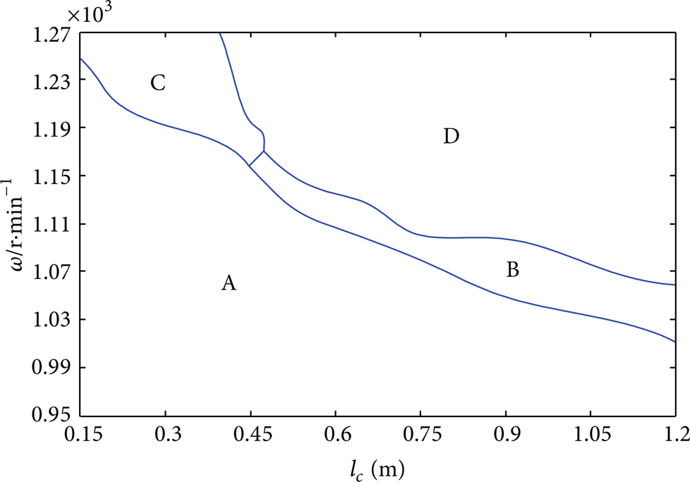
The distribution of stable or unstable region in intersection hole drilling process.

The stable periodic motion of the center of drilling shaft for ω = 1035 r/min, l c = 576 mm.

The Period-doubling motion of the center of drilling shaft for ω = 1090 r/min,l c = 768 mm at a nodal.
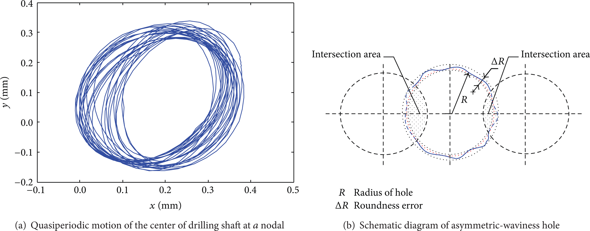
The quasiperiodic motion of the center of drilling shaft for ω = 1237 r/min, l c = 323 mm at a nodal.
Moreover, it can be seen from the distribution of 3 regions of “A,”“B,” and “C” that, in the drilling initial stage, the regional area of the drilling shaft stable motion is much larger so that the selectable range for the cutting rotational speed is much wider, but, with an increase in machining depth, the selectable range for the cutting rotational speed will be gradually decreased. It can be known from the analysis of variable shaft length that it is mainly because the drilling shaft rigidity is reduced with an increase in its length. Accordingly, the cutting tool stability is also decreased obviously. This trend accounts for the phenomena observed in the experiments by Deng and Chin [10]. In addition, it can be seen from Figures 7–9 that with an increase in rotational speed, whirling magnitude value at a nodal point increases obviously, whereby resulting in an increase in roundness errors of the holes to be machined. As a result, this law has been proved in the correlative experiment [7, 10]. “D” region is the complete unstable machining region for the drilling shaft. Owing to the drilling shaft unstable motion, the drilling tool can occur easily the tool edge broken, worn or even the machine damaged, and so forth. Accordingly, in practical machining, the cutting parameters in this region can by no means be selected for the utilization.
6. Conclusions
The practical deep-hole drilling shaft system is subject to such actions of multifactors as the auxiliary supports, cutting fluid forces cutting forces fluctuation, and so forth. Accordingly, this is typical high-dimension local nonlinear dynamic system. In this paper, the drilling shaft system with auxiliary supports was modeled based on the Timoshenko element model so that the shear deformation and rotational inertia are taken into full consideration in the model. The modal synthesis technology with freeinterface offers a kind of freedom degree shrinkage method. The nonlinear hydrodynamic forces and the nonlinear freedom degrees are retained in the physical space. The linear freedom degrees can be converted into the modal coordinate to truncate the feature modal for reducing the system linear freedom degrees. The shrunken system can retain the whole nonlinear features so as to ensure the nonlinear analysis of the drilling shaft system.
With the multi-span flexible rotary drilling shaft system as the analytical objective, the above-mentioned reduced-order method is adopted to study the whirling vibration of the deep-hole drilling shaft under the different drilling shaft lengths, and, with machining intersection holes as the example, the stable region of drilling shaft motion is obtained in the selected drilling depth and the cutting speed parameter space. Also, the relationships between the cutting machining parameters and the hole roundness errors are discussed. A large number of numerical computation examples indicate that the calculation method suggested in this paper can not only decrease the freedom degrees of drilling shaft system for solutions to the coupling dynamic system effectively but also save the computation resources as well. Furthermore, this method can provide the theoretical bases for the dynamics design of complicated deep-hole machining equipment and the analysis of machining.
The future research will focus on the dynamic recognition and whirling vibration suppression of drilling tool in deep-hole machining by the proposed method. This is an important problem for the success of solving the drilling precision and real-time controlling over drilling tool stability.
Footnotes
Appendices
Acknowledgments
This work is supported by the National Natural Science Foundation of China (Grant no. 51105305), the Major Research Program of Shaanxi Province of China (13115 Project, Grant no. 2009ZDKG-25), and the Natural Science Foundation of Department of Education of Shaanxi Province of China (Grants no. 2010JK695 and No. 12JK680).