
Abstract
The proliferation of wireless sensor networks is one of the main hardware components enabling the creation of the Internet of Things. As sensor nodes are being deployed in a wide variety of indoor and outdoor environments, they are in general battery-powered devices. In fact, power provisioning is one of the main challenges faced by engineers when deploying IoT-based applications. This paper develops crosslayer architecture, integrating smart and power-aware protocols with a low-cost and high-efficiency power management module, which is the basis of long-lasting of self-powered WSNs. The main physical components of the proposed architecture are a wireless node comprising a set of small solar cells responsible for harvesting the energy and an ultracapacitor as storage device. Energy consumption is reduced significantly by varying the sleep/wake duty cycle of the radio module. For environments with only a few hours of sunlight per day we present the feasibility of ensuring long-lasting operation by means of adapting the duty cycle scheme according to the energy stored in the ultracapacitor. Our experiments prove the feasibility of a long-endurance outdoors operation with a low-complexity power management unit. This is an important advance towards the development of novel IoT-based applications.
1. Introduction
The study of reliable and long-lasting power management systems for wireless sensor networks is nowadays the main subject of a large number of research efforts. Three main issues are being explored, namely, (1) energy harvesting, (2) energy storage, and (3) power-aware protocols. The former two mainly deal with the design and use of power generation and energy storage based on renewable energy systems and rechargeable energy storage devices, while the latter deals with the design of power-aware protocol mechanisms.
Despite the advances in batteries and the reduction in energy requirements of electronics, the use of energy harvesting techniques needs to be considered in order to satisfy the requirements for low weight and volume, long life, and limited environmental impact [1]. The use of environmental energy is a feasible source for low-power wireless sensor networks [2, 3]. Among the various sources of renewable energy for outdoor applications, solar power is one of the most abundant and accessible energy sources to extend the operation of such networks. Several systems that have been designed to date aim to provide an efficient and reliable source of solar-based energy to WSNs, ranging from sophisticated adaptive power modules [4] to low-complexity cost-effective solutions capable of providing simple ON and OFF signalling to the WSN node [5].
Regarding energy storage, deployments of WSNs have been carried out using rechargeable batteries [6], capacitors [5, 7], or hybrid architectures including both batteries and capacitors [8]. The final decision on the type of device being used for energy storage depends, among other things, on the WSN power operation requirements, the availability of solar power or other forms of renewable energy, and considerations of cost, size, and environmental concerns [1]. In particular, ultracapacitors are now being considered as a power source for applications such as toys and portable lamps. Some advantages of using capacitors for energy storage are that capacitors may be designed for the life of the product. Although additional power conditioning may be necessary on both the input and output of the capacitor [9], using capacitors avoids the extra replacement cost and the restrictions imposed by the limited number of charge/discharge cycles of a battery [10].
As for the power management systems to control the power supply, a wise coupling has to be performed to obtain the optimum use of the energy stored. For example, in [4] a power transferring circuit for optimally conveying solar energy to rechargeable batteries was introduced. In [5] the authors presented a microsolar sensor board prototype with miniaturized photovoltaic modules and capacitors as energy storage devices. Their experimental results showed the impact of light intensity variations on the activity of the sensor node and its sustainability. An interesting experiment was performed in [6], in which the authors showed a prototype working for two years using solar energy and rechargeable batteries. In [8] the objective was to develop an intelligent hybrid power system to create a self-sustaining wireless sensor node. The power source consisted of solar cells, photovoltaic and thermoelectric generators, a lithium ion battery, ultracapacitors, and a power management subsystem.
In this work we focus on the cross-layer design of a very low-cost and reliable power source (ATON II) for outdoor deployments of WSNs in changing microclimate conditions. For power generation we use solar energy, for energy storage we use an ultracapacitor, and for power management we have designed a power-aware protocol that adapts the energy consumption according to the current energy supply. In other words, we present a power management framework incorporating a solar-powered batteryless power supply prototype ATON II which is properly coupled with a power-aware MAC protocol whose operation is based on the dynamic adaptation of its duty cycle based on the microclimate conditions. Real-world experiments show the prototype works continuously in two extreme conditions: (1) with a fixed and long duty cycle and (2) with a short and variable duty cycle.
The paper is organized as follows. We start by reviewing the state of the art in relation to related harvesting mechanisms and energy efficient MAC protocols in Section 2. Section 3 gives details on the operation of the synchronous awake MAC (SA-MAC) protocol, a power-aware MAC protocol. Section 4 describes ATON-II, a smart and low-cost energy harvesting and storage device. Section 5 presents the experimental results of a prototype that has been extensively evaluated in field trials for more than a year. Finally, Section 6 summarizes the major ideas of this study and presents our future research plans.
2. Motivation
One of the most important objectives in the design of a wireless sensor device is to obtain a balance between feasibility, efficiency, versatility, power consumption, and cost. In order to enable the long-lasting operation of the nodes in a WSN, the proper integration of power-efficient hardware entities and protocols is the major task to be undertaken.
Figure 1 shows the main components of our proposed solution: a solar panel, a power management and storage unit, and a mote running an energy-aware protocol. Figure 1 also shows that the power management unit and storage units interact with the energy-aware protocol following a cross-layer approach.
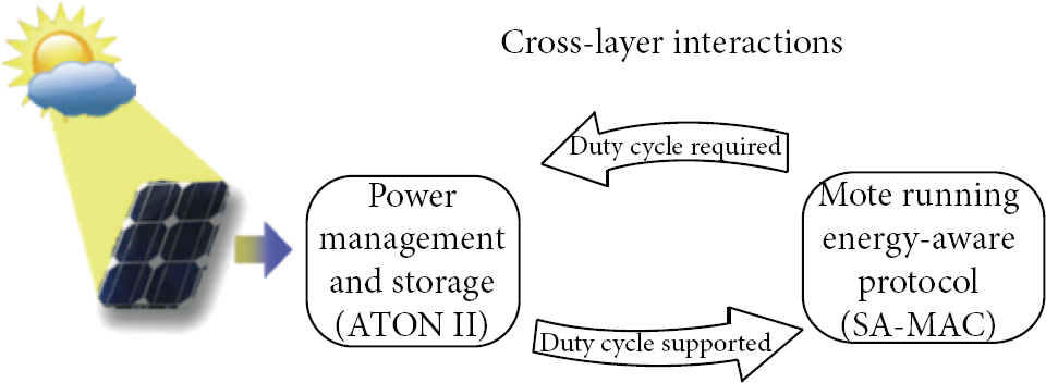
System architecture showing the main modules.
The smart coupling of the power management unit and a power-aware protocol requires an analysis of the requirements of various types of applications as well as the design of power-aware protocols capable of operating under changing conditions. The latter is particularly important in WSNs powered by batteries or ultracapacitors. In such environments, the efforts should focus on the design of a protocol capable of adapting its power operation mode by taking into account the availability of the energy stored in batteries or ultracapacitors. As for the applications, some applications, such as gas metering [11], may require the transmission of information at regular intervals, while others may compromise on the transmission times in order to get pieces of information via a reliable transmission service.
In order to meet the two aforementioned requirements, namely, long-lasting operation and energy-efficient protocols, we introduce a power-aware MAC protocol into the proposed systems architecture. The proposed protocol operates under the time division multiple access (TDMA) principle using a variable duty cycle enabling both power saving and the synchronization of the various entities through a well-defined and limited set of primitives. This cross-layer feature is a form of energy-aware protocol which has been mentioned in [12] and simulated in [13, 14].
In the past, among the various energy-aware protocol paradigms, MAC based on TDMA principles has been recognized as one of the preferred alternatives. Other interesting alternatives, such as [15], focused on improving specific problems such as low-power listening. In the framework of power-constrained MACs, the main idea relies on the assignment of a given time slot to each of the nodes composing the network. In this way, each node gets to know the time and period length during which it must be ON to carry out the communication operations (send/receive) [16].
Much has been published on energy-aware protocols, and the reader is referred to surveys such as [17–19] for a comprehensive overview of the energy-efficient MAC protocols developed to date. Some of these works propose dynamic-duty-cycle-based MAC protocols [15, 20, 21], but their objective is different from the one pursued in this work. For example, in [20] duty cycles are based on the traffic class or type of service to offer some precise quality of service for multimedia transmissions over sensor networks. In [15] nodes optimize their local power consumption as they adapt the check intervals in low power listening (LPL) to the current data traffic. Instead of adapting the power consumption to the traffic, in our design we adapt the data traffic (i.e., the duty cycle) according to the energy available in the storage device; hence, the capability of adjusting the duty cycle of operation of the WSN node helps to extend the endurance of a batteryless operation. Moreover, the variable duty cycle proves effective at keeping the whole system fully operational even when nodes operate with energy supply at different levels. This operation is based on the use of the SA-MAC protocol for synchronization.
The main contribution of our work is twofold: (1) the design of a cross-layer system architecture comprising an energy harvesting and power management unit and a power-aware protocol and (2) an in-depth evaluation of the proposed solution through a set of experimental trials.
3. SA-MAC Protocol
SA-MAC is an efficient, synchronous, and TDMA-based protocol. The main aim of the SA-MAC protocol is to synchronize the transmission period in the sender node with the received period in the destination node. A complete description of SA-MAC can be found in [16]. In the following, the operation of the protocol will be described by considering a network consisting of a sink node (base station, BS) responsible for gathering all the data sensed by all the other nodes. Some of the other nodes may have, when required, to act as relays enabling the forwarding of the collected data to the sink station. Figure 2 shows that the operation of SA-MAC is divided into two phases: (1) the setup phase and (2) the synchronization and data transmission phase.

The packet exchange in the SA-MAC protocol for the given topology.
During the set-up phase of the SA-MAC protocol the network is configured following a simple schema of minimum hop count to the sink node to establish a TDMA transmission schedule to be used at later stages. In this phase the nodes exchange three types of packets, namely, discovery packets (DSC), delay packets (DLY), and acknowledgement packets (ACK). In the simplest scenario the set-up phase is initiated by the base station (i.e., the sink node). The base station first announces its presence as a parent node so that all the nodes within the coverage area may initiate the exchange. All nodes that become aware of the presence of the base station start to broadcast discovery packets (DSC). Upon receiving a DSC packet the base station sends a DLY packet to the corresponding node. The delay packet indicates the time slot that is assigned for transmissions from the sensor node to the base station. The node acknowledges the DLY packet with an acknowledgment packet ACK. In this way, the sensor node finishes its association to the base station and then it may become a parent node for other nodes. In our example, nodes N1 and N3 communicate directly with BS, and N2 uses N3 as a relaying node to communicate with BS.
Once the network has been configured, the base station waits for a period of time, during which no new nodes are detected, and then the base station will transmit an SYN packet indicating the beginning of the second phase. The data transmission phase starts at the base station and an SYN packet is propagated among successive levels. Nodes in this phase turn ON/OFF the radio only during the time slot assigned during the first phase of the protocol, in which the basic duty cycle was defined.
3.1. Cross-Layer Interaction between ATON II and SA-MAC
Nowadays, the cross-layer integration of different elements composing a wireless sensor network is seen as the most effective approach to the deployment of long-lasting and self-configuring networks and protocols.
It is widely recognized that radio systems are the main sources of energy wastage due to overhearing and to the conflicts arising during the collision resolution mechanisms implemented by most MAC protocols.
Designing an energy-efficient MAC protocol reduces energy consumption in a significant way due to its direct control over the RF module, turning it ON and OFF according to the operation duty cycle.
SA-MAC has to turn ON and OFF the node's radio to ensure that the consumption due to communications is significantly reduced. If the network has a high number of nodes, the listening time of the parent nodes will increase as will its power consumption. The cross-layer interaction between SA-MAC and ATON II shown in Figure 1 happens during phase 2 of SA-MAC. More specifically, Figure 3 shows the way in which during the synchronization and data transmission phase of SA-MAC the duty cycle is adapted by reducing the duty cycle when the charge of the ultracapacitor decreases, therefore improving the node's lifetime. ATON II continuously monitors the voltage level in the ultracapacitor and adapts the radio's duty cycle proportionally to the ultracapacitor's energy. When low energy is detected in the ultracapacitor, the period between messages is increased in units per synchronism. This adaptation is due to the interaction of the MAC layer with the physical layer. The SA-MAC protocol sets up synchronous units that ATON II will use in terms of the duty adaptation.

SA-MAC timing diagram with duty cycle adaptation depending on sunlight conditions.
By using a sufficiently long fixed duty cycle and a large ultracapacitor we should be able to obtain sustainable operation for over a year, the longest period of continuous operation under real conditions reported among [1, 11].
For applications with shorter duty cycles, the physical layer is tuned with the MAC layer, working together to obtain an optimized performance by adapting the duty cycle of operation to the charge/discharge cycles of the ultracapacitor used to store energy. Real experiments show the prototype working continuously with a variable duty cycle for 48-hour periods.
4. Design of ATON II
4.1. ATON II versus Other Power Supply Designs
Our first power management prototype, ATON [22], took into account that the amount of energy available in an outdoor environment is very large. The power source in ATON consisted of solar cells, a lithium ion battery, two ultracapacitors, and a power management subsystem. This first ATON power system was similar to the one reported in [6], but an important difference was that in our case we used the MAC protocol SA-MAC in order to adapt the RF module duty cycle to the ultracapacitor's charge/discharge cycles. We have improved upon the first prototype (ATON) with a new design, ATON II, which provides superior capabilities in energy storage and management performance. A solar panel is used in our new design, as in ATON, but this new prototype avoids the use of maximum power point (MPP) tracking algorithms [4, 23]. Although operating at the MPP provides the best use of the solar panel, operation at the MPP requires a sophisticated adaptive stabilizing circuit that is costly and increases the power consumption of the power management system. Since we are not operating at MPP, we avoid the corresponding high-complexity analysis for the MPP. The main objective in designing ATON II was to reduce the power consumption to the minimum with restrictions on resources, such as CPU or memory. That is why it was decided not to use a stabilizer circuit. Moreover, the loss in efficiency in the operation of the solar panel does not have an impact on the operation of the network.
Although there exists this slight reduction in efficiency, our circuit is much simpler and consumes less energy during operation. Furthermore, this circuit uses a single ultracapacitor for storing energy. Although it has been argued that only a hybrid solution [8] can sustain a WSN node during long periods when solar energy is not adequate, our cross-layer design proves that a single ultracapacitor can provide a high enough energy density for many days by adapting the duty cycle in the RF and MCU units of the wireless node to the ultracapacitor's charge/discharge cycles, keeping synchronization with the SA-MAC protocol [16].
4.2. Energy Demand
In order to make sure that in our design the energy demand and supply are properly balanced, we will elaborate an energy budget taking into account the duty cycle dictated by the application. For this purpose, we will investigate
the energy requirements the energy requirements the energy, the energy,
4.2.1. Energy Requirements of the Node
The mote (throughout the paper we will use the terms node and mote, interchangeably) used in our experiments is a Telosb node. Table 1 indicates the energy consumption of the various components of the mote, according to the datasheet [24].
Energy consumption of the different components of the mote and ATON II.

Overall, the mote has a maximum consumption of
4.2.2. Energy Requirements of the Power Supply
The ATON II design schema is shown in Figure 4. It has been based on a single chip boost converter configuration. To implement the energy management unit we use a low-input voltage DC-DC converter [25]. The converter has a very low quiescent current of only 5.5 μA capable of handling a maximum output current up to 150 mA. This stage establishes an output voltage of 3 V with up to 95% efficiency. One of the most attractive features is the start-up voltage, 0.7 V, while most low-power converters have a startup voltage greater than 1 V. It is at this voltage that the converter is able to ensure a stable output voltage. Due to this lower voltage, we can optimize the use of the ultracapacitor, that is, manage its energy more efficiently.
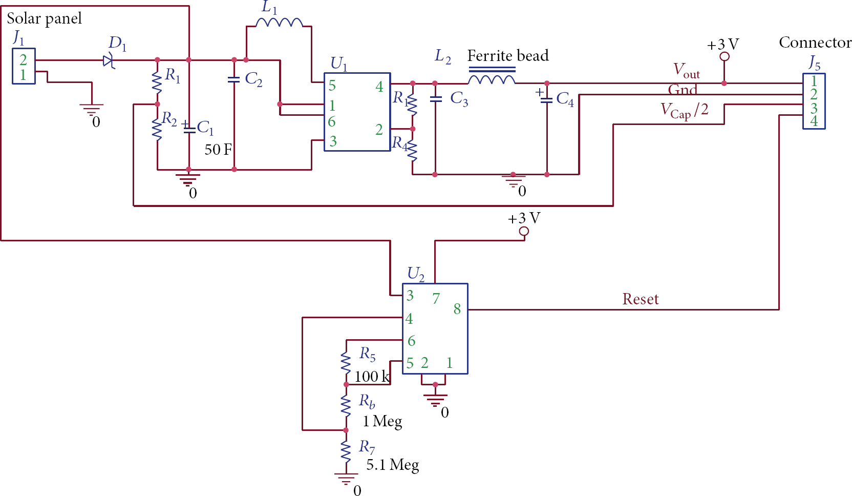
ATON II design schema.
In addition, ATON II includes a hardware reset unit. This unit consists of a very low-power comparator (ultralow quiescent current of 0.3 μA) with hysteresis, which resets the node if a low voltage input occurs. This voltage is set to 0.9 V approximately to avoid damaging the mote and to prevent a wrong start-up in it. The value differs by 0.2 V from the DC-DC start-up voltage to ensure a safe power-good state in the converter because this performance can be affected by the temperature.
Table 1 summarizes the current consumption of ATON II. Overall, the power supply has a maximum consumption of
4.2.3. Energy Delivered by the Solar Panel
The typical current-voltage characteristics of the solar panel are shown in Figure 5. The maximum power point (MPP) corresponds to the “knee” of the curve and is 2.9 V × 44.5 mA or 129.05 mW (see Figure 5).

Experimental curve of the solar panel, voltage versus current.
The efficiency at our solar panel (η) is given by


Using (2) we calculate the (average) energy generated by our panel throughout a year as follows: the effective area of our solar panel is composed of six solar cells of 17 mm × 17 mm connected in serial fashion, so the effective area is 17.34 cm2. According to (1), considering
In our city the annual average irradiance is 228.17 W/m2 (southern aspect and 30° inclination) [26]. If we multiply by the efficiency of our panel, we obtain 16.885 W/m2, which applied to the area of 17.34 cm2 gives
4.2.4. Energy Stored by the Capacitor
In order to store the energy generated by the solar panel, we use a single ultracapacitor. The capacitor used has a capacitance of 50 F and a low equivalent serial resistor (ESR) (≤0.1 Ω at 1 kHz) to avoid high voltage drops. We chose this value since it presents the best size-capacitance relationship among the commercial solutions. This ultracapacitor is tied to the solar panel through a very low forward voltage Schottky diode (≤3 Ω at 100 mA) to avoid reverse current, which could discharge the ultracapacitor, and minimize the voltage drop across the diode. The diode is capable of handling a continuous forward current of 1 A. This value determines the maximum current at which the ultracapacitor can be charged. In our case this does not constitute a problem since the maximum current generated by the solar panel never exceeds 60 mA. Actually, ATON II could use higher current solar panels as long as the maximum current never exceeds 1 A (previous version could only handle a current of 200 mA), but the use of a higher current solar panel will only improve the speed at which the ultracapacitor is charged. The maximum output current in our system will depend on the DC-DC unit characteristics (150 mA) and not on the solar panel size/power.
If we consider an ideal capacitor, the energy stored in the capacitor is

4.2.5. Energy Budget
The energy required by the node (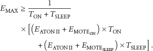
According to the parameters shown in Table 1 we can adjust the duty cycle of the node to satisfy (4). Figure 6 shows the estimated hours of operation according to the energy saved in the capacitor and the duty cycle used, assuming that the solar panel is not providing energy. For example, using a 5% duty cycle and a capacitor charged at 75%, the mote will be able to operate for about 15 hours. Thus, Figure 6 shows the relation between the estimated hours of operation using only the energy stored in the capacitor versus the value of the working duty cycle. How often a quantity must be sensed without putting at risk the quality of the data really depends on how critical the data being sensed is and on the data processing techniques used to extract the information from the sampled data. In critical applications such as gas metering and monitoring for leakage detection, it would be advisable to operate with a high duty cycle, which can require operation with power obtained from the electric network, backed up with batteries. ATON II is designed to be used in applications in remote areas where perhaps there is no electric power but the sensed data can be used to provide some statistics about weather conditions and so forth. Moreover, the size of the capacitor can be increased in order to extend the operation without sunlight.

Estimated hours of operation versus the duty cycle used for different energy levels in the cap.
4.3. A Note on the Output Stage
Radio frequency devices are very sensitive to noisy signals. A noisy power supply can affect the RF performance providing an undesirable signal modulation as well as a wrong operation in the core of the mote. This undesirable behaviour could greatly affect the data loss rate and consequently the network's reliability. Since our design uses a high-frequency switching converter, the output will present a voltage ripple with the same frequency as the switching one. This ripple increases with high currents and low-input voltages. Due to this problem, we must minimize this ripple even if we use very low currents. In order to reduce this output ripple, we implement a filtering stage at the output of the energy management unit. This filter is made of a set of LC components using very low ESR ceramic capacitors and a choke inductor. This inductor has a 0.1 Ω resistance and a 1 K Ω impedance at 100 MHz. In this way, any high-frequency component in the power supply line will be reduced significantly and the performance in our energy management unit will be improved. The output of this filter is tied to the external socket of our prototype, which fits exactly into the external socket in the Telosb mote providing the power supply.
4.4. ATON II Setup Cost
Cost can be divided into the cost of the equipment, set-up costs, and maintenance costs. By using a capacitor, the cost of the power management system is reduced compared with the use of a battery. With respect to the set-up costs, these are essentially the same as the set-up costs using other power management systems. The cost of our unit is mainly characterized by the ultracapacitor and two integrated circuits. According to the international electronic component supplier “Digi-Key”, the cost of these components, at the time of publication, is shown in Table 2.
ATON II main component costs.

The rest of the components will not exceed 1$, and the price for the PCB, manufacturing, and the assembly process could be reduced to less than 1$ as well, making ATON II a harvest unit with an attractive cost less than 9$ at a production scale. Table 3 shows some harvesting solutions that the reader can find on the market.
Some commercial harvesting solutions found in the market.

All previous solutions are development kits which offer a whole developing harvesting system (USB dongles, technical CDs, microcontroller, etc.) and are not final deployable products. The systems are based on different storage technologies and different energy sources. As a quick reference, the first system (Silicon Labs) uses a thin film battery as a storage device, and the second system (Mide Technology) uses a standard electrolytic capacitor. The energy source in the first one is a solar cell and in the second one a piezoelectric device. The use of a capacitor also reduces the maintenance costs because the capacitor can have the lifetime of the node, and we do not need to replace batteries when they lose the ability to be charged.
In order to compare our prototype with other systems, we have two candidates: the second and third solutions. The complexity level is similar and they use capacitors as a storage device. The prices of these units are considerably higher than that of our prototype, and the fact that none of them have real long-term application data to demonstrate their usability and performance could be the main disadvantage. This quick analysis asserts the low-cost premises and shows the advantages of using a low-complexity and reliable energy harvesting system for low-power wireless sensor networks.
4.5. A Summary of ATON II's Main Features
ATON II is cleverly designed to manage solar energy and supply our sensor nodes perpetually without batteries, using an ultracapacitor of 50 F as a main energy accumulator. ATON II adapts the photovoltaic energy in a smart way to the right level demanded by our motes. The mote samples the voltage at the ultracapacitor and establishes the corresponding duty cycle to improve the mote's consumption. A picture of ATON II is shown in Figure 7. Some improvements with respect to a previous version presented in [22] are as follows.
The capability of handling more powerful solar panels as long as the maximum current never exceeds 1 A. The main energy storage is a 50 F ultracapacitor. The power consumption of the unit is 90 times less than its predecessor; the consumption is caused by the hardware reset unit and the DC/DC converter, giving a total of 5.8 μA. ATON II is more robust thanks to the hardware reset unit, the support for bigger solar panels, and the filter for the output current. It can be used for different kinds of motes, with a maximum consumption of up to 150 mA. Obviously, the rate at which the energy stored in the capacitor is consumed will mainly depend on the duty cycle of the radio system. It has a smaller board. In terms of size, the board is smaller than the mote board (only 60 × 25 mm).
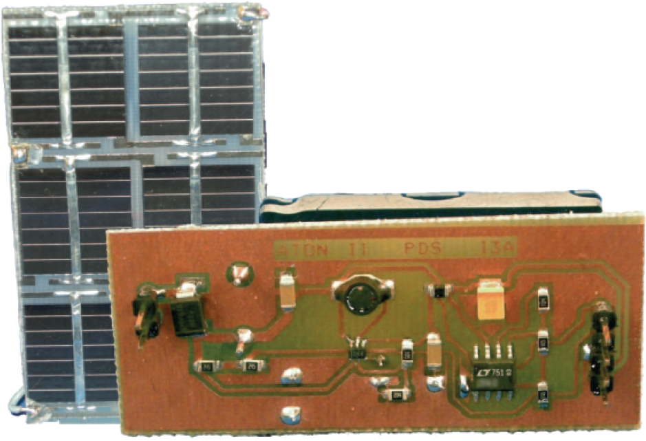
ATON II with solar panel.
5. Tests and Experiments
In this section we describe three real-world tests and experiments that illustrate the capabilities of our system.
ATON II node energy demand. This test consists in verifying that ATON-II is able to meet the energy demands of the node and the SA-MAC protocol. ATON II long-lasting operation. In this test the sensing cycle is fixed to 60 s, and the RF module was turned on during 10 ms and off during 59.99 s, resulting in a duty cycle of 0.016% for the child node, and for the parent node the RF module was turned on during 200 ms and off during 59.8 s, resulting in a duty cycle of 0.33%. This test lasted a whole year. ATON II can work with a variable duty cycle. Nodes powered with ATON II dynamically adapt the sensing cycle between 1 and 16 s for operation during periods of time with no sunlight; that is, the RF module was turned on during 10 ms and off during a variable period that went from 0.99 to 15.99 s, resulting in a duty cycle between 1% and 0.0625%.
Table 4 summarizes the main parameters of the scenario used in our experimental trials.
Scenario description for each experiment.

5.1. Verifying Energy Demands
Figure 9 shows the current consumption during the data transmission phase between the parent node N3 and child node N2 shown in Figure 2. During the experiment we used a duty cycle of 2.5% (
Replacing in (4) the duty cycles detailed above for both nodes and the consumption parameters shown in Table 1 (similar values to those obtained with the oscilloscope), we have an energy requirement of 1.94 × 10⁻³ J and 0.13 × 10⁻³ J, respectively. Under these conditions, the energy demanded by the node,
5.2. One Year with ATON II on the Roof
The test scenario is composed of two nodes, with the base station node receiving packets from a child node, running SA-MAC, and with a fixed duty cycle according to the data packet rate used. The prototype was placed on the roof of our research institute, as shown in Figure 8 (left).
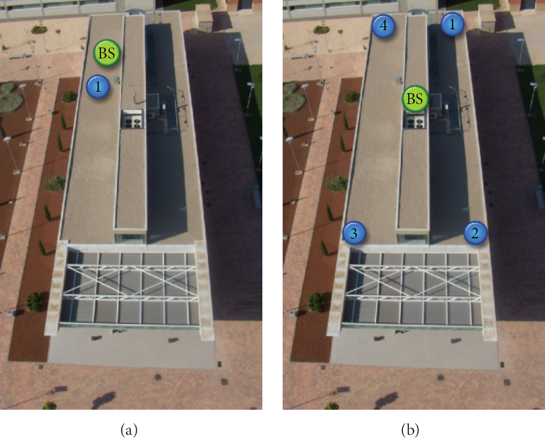
Scenario used for test b (left). Scenario used for test c (right).
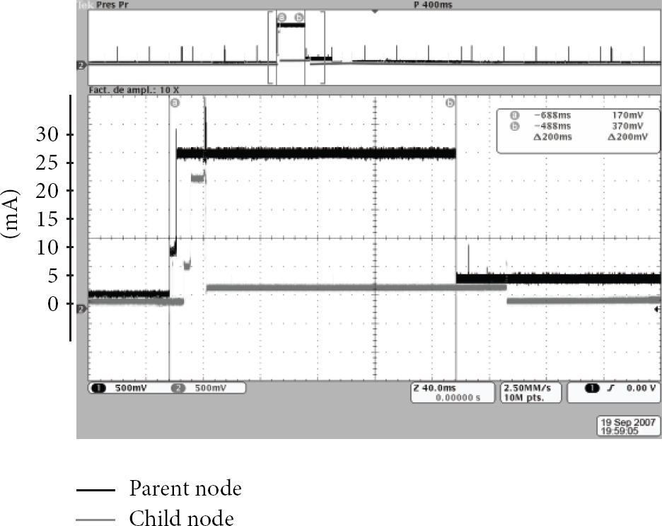
Signals showing current consumption of motes Telosb running SA-MAC. The black line is for the parent node N3. The gray line is for the child node N2 (see topology in Figure 2(a)).
Figure 10 shows the experimental results for the one-year test, which prove the long-lasting feature of our system with a fixed packet rate of 1 packet every 60 s. Figure 10(a) shows the output voltage from ATON II, the ultracapacitor's voltage, and the charging current in the parent node. Similarly, the data captured for the “son” node is shown in Figure 10(b).

Experimental results for the one-year test using ATON II and SA-MAC with motes Telosb.
It can be seen in these plots that the ATON II output voltage level is in the range of 3 to 3.3 V, a value that is in accordance with the supply characteristic of the nodes. Furthermore, by comparing both figures we can observe that the discharge voltage level in the ultracapacitor is slightly lower for the parent node, which is due to the higher duty cycle implemented at the parent node. In order to further analyze the whole test, we split the figure into periods of one month each. Figures 10(c) and 10(d) show the sunniest months and the least sunny ones in our city, respectively. These months have been chosen due to the huge difference in the number of sun hours, resulting in large differences in the values of the solar cell current and the ultracapacitor's stored energy. In Figure 10(d) the ultracapacitor's level in the discharge phase is lower than the level in Figure 10(c) due to the scarcity of sunny days.
As the solar cells receive fewer hours of sunlight in the winter season, mainly at the end of the day, the voltage in the ultracapacitor drops to a much lower level than that observed in the summer season. Hence, in order to get the ultracapacitor charged from this level, the solar panel will have to supply a bigger current. This effect can be observed in Figure 10(d), where the current spikes are bigger than in Figure 10(c).
The opposite scenario can be observed in Figures 10(a) and 10(b), which cover May and June. In those months our solar cells were in the most favourable orientation to obtain the maximum light at the end of the day, and consequently the ultracapacitor's voltage was higher than the rest of the months at night. Therefore, a lower current is required to achieve a fully charged capacitor, as indicated by the low current spikes.
5.3. Dynamic Adaptation of the Duty Cycle
In the previous section we have shown operation over a year-long period using a fixed sensing cycle of 60 s with two nodes. It remains to be seen if we can achieve continuous operation with shorter sensing cycles (of less than 16 s) even in periods of time with no sunlight. For this purpose we ran an experiment with four nodes (BS and child nodes: 1, 2, 3, and 4) located at the four corners of the roof of a two-story building. Figure 11 shows the luminance conditions and the energy stored in the capacitors. The energy supply is shown for two nodes operating with a fixed duty cycle (nodes 2 and 3) and for two nodes operating with an adaptive duty cycle (nodes 1 and 4). It can be observed that at some point in the night the two nodes with a fixed duty cycle run out of energy and stop operating, while the two nodes with an adaptive duty cycle operate continuously. Figure 12 also shows the luminance conditions and the energy stored in the capacitors, but this time with all the nodes operating with an adaptive duty cycle. As can be observed, operation of the four nodes is now continuous throughout the whole day-night cycles.

Plots of the luminosity (a) and the energy Ei supply available to each node:
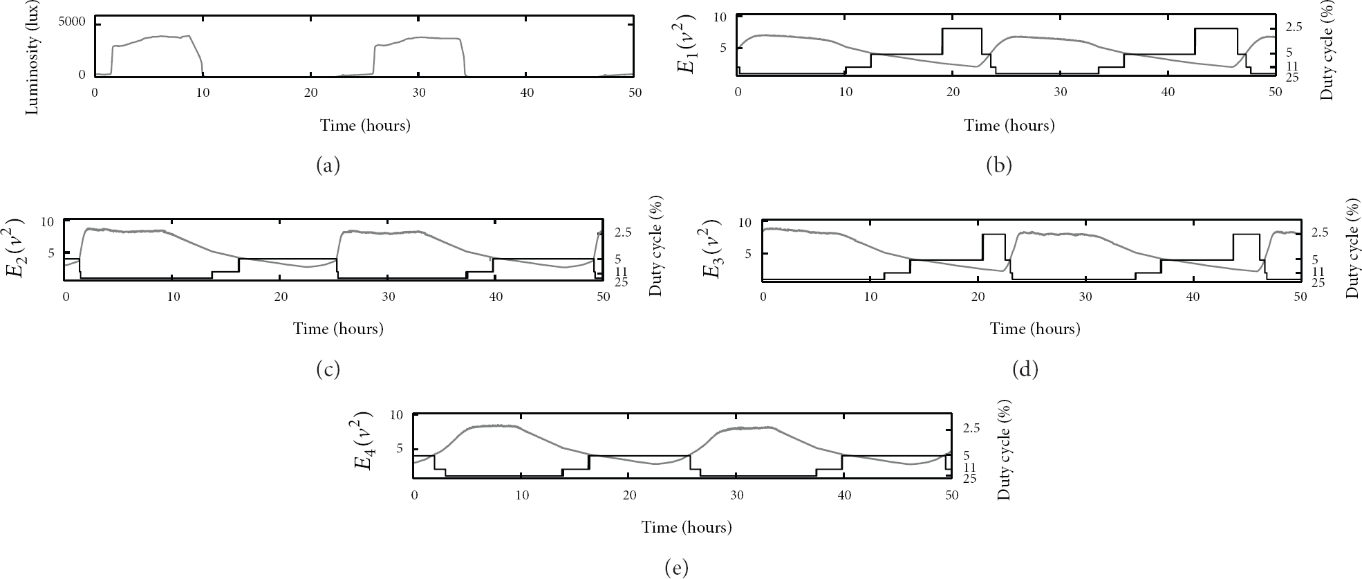
Plots of the luminosity (a) and the energy Ei supply available for each node:
6. Conclusions and Future Work
The concept of IoT has spread into multiple fields. Despite significant technological advances, difficulties associated with the evaluation of IoT solutions under realistic conditions in real-world experimental deployments still hamper their maturation and significant rollout [27]. The success and wide acceptance of IoT applications will require the development of efficient platforms and architectures tested in real environments. We have designed and developed a real power-efficient protocol architecture for WSN that uses sunlight as a source of energy. The design includes a low-cost but efficient and reliable power management module, ATON II, working in a cross-layer fashion with a mote running a version of the TDMA protocol SA-MAC implemented in our laboratory. Using solar cells and a large ultracapacitor, and operating with both an adjustable and a fixed duty cycle, we were able to obtain continuous outdoor operation throughout whole day night cycles and sustainable outdoor operation for over a year. Our challenging future work will be related to the incorporation of our framework in mobile nodes belonging to body area networks.
Footnotes
Conflict of Interests
The authors declare that there is no conflict of interests regarding the publication of this paper.
Acknowledgments
This work has been jointly supported by the MINECO and European Commission (FEDER funds) under the project no. TIN2012-38341-C04-04 and by a CONACYT (Mexico) Research Grant no. 0139822 and by Asociacion Mexicana de Cultura A.C.