
Abstract
A lifting body unmanned aerial vehicle (UAV) generates lift by its body and shows many significant advantages due to the particular shape, such as huge loading space, small wetted area, high-strength fuselage structure, and large lifting area. However, designing the control law for a lifting body UAV is quite challenging because it has strong nonlinearity and coupling, and usually lacks it rudders. In this paper, an explicit nonlinear model predictive control (ENMPC) strategy is employed to design a control law for a saucer-shaped UAV which can be adequately modeled with a rigid 6-degrees-of-freedom (DOF) representation. In the ENMPC, control signal is calculated by approximation of the tracking error in the receding horizon by its Taylor-series expansion to any specified order. It enhances the advantages of the nonlinear model predictive control and eliminates the time-consuming online optimization. The simulation results show that ENMPC is a propriety strategy for controlling lifting body UAVs and can compensate the insufficient control surface area.
1. Introduction
A lifting body is basically an aerial vehicle that chiefly or solely generates lift by its body [1]. Unlike traditional UAVs which obtain lift mainly by the wings, lifting bodies generate little or small amount of lift by wings and some of them even have no wings. The first lifting body XF5U was designed by the American engineer Charles H. Zimmerman and showed advantageous aerodynamic characteristics [2]. Then, national aeronautics and space administration (NASA) gave more superiority in loading space, low-speed controllability, structure strength, and so forth, by studying M2-F1, M2-F2, M2-F3, HL-10, HL-20, X-24A, X-24B, and many other kinds of lifting bodies [3]. But these design schemes weren't taken seriously for many reasons at that time. From a technical point of view, the dominant issue has been stability and control, which to this day continues to plague this class of vehicles [1]. With the wide application of UAVs [4], people draw more attention to the lifting bodies which can overcome some shortcomings of conventional ones and meet more aviation demands. Therefore, many practical challenges are waiting to be solved for the lifting body. One of the most important aspects is the control system.
There are many kinds of control strategies, such as fuzzy sliding mode control, adaptive control, robust control, and optimal control, that can be used for nonlinear dynamic system [5]. Nowadays, model predictive control (MPC) has been regarded as a prospective method for highly nonlinear dynamic systems such as UAVs [6]. MPC strategy uses a dynamic model to predict the future behavior of a plant and subsequently an optimal control decision can be made based on the estimated future state and the desired future state [7]. The linear model predictive control is used by modeling a discrete linear system [8]. To develop MPC for nonlinear system, many approaches have been proposed, such as the State-Dependent Riccati Equation Technique [9], using second-order model approximation [10], and solving the Hamilton-Jacobi-Bellman equation by power series expansion [11]. However, the methods are mentioned above require a plenty of online computations which is often computationally complex and time consuming and the real-time NMPC implementation is usually limited to slow processes where the sampling time is sufficient to support the computational needs [12]. Chen developed a nonlinear model predictive control (NMPC) using approximation. This method can stabilize the original nonlinear systems by properly choosing predictive times and the order for Taylor-series expansion [13]. It is assumed that control weighting is not in the performance index and that control order is the difference between the Taylor-series expansion and the relative degree of the system [14]. According to this method, Liu et al. introduced an explicit NMPC, which inherits the advantages of the NMPC but eliminates the time-consuming online optimization [15]. The control signals in this method can be calculated instantaneously to respond to the fast dynamic systems and effectively restrain the disturbances. Besides, by removing the online optimization process, the onboard hardware can be simplified and the software development is accelerated.
The controlled object we used in this paper is a saucer-shaped lifting body UAV. The body of this UAV is designed like a saucer to provide a large number of internal spaces and improve lifting area. According to the special shape of this UAV, it is easy to conclude that the lateral maneuverability is not as good as a conventional aerial vehicle. Consequently, a better control system is needed to avoid the shortcomings of this UAV including other kinds of lifting body aerial vehicles. Therefore, we design a control law using the ENMPC strategy mentioned in this paper. The results are compared with the NMPC algorithm and conventional PID control law. Besides we also induce some wind disturbances to investigate the robustness of this method which is not discussed in any references. Due to the advantages of ENMPC, the control framework has a low complexity and high reliability. Therefore, the UAV has a nice response effect. This paper expands the application range of this method and gives other lifting bodies a feasible control strategy. The wind disturbances simulation also proves that this method has good robustness.
The remainder of this paper is organized as follows. Section 2 introduces the mathematical model of the saucer-shaped lifting body UAV. Section 3 describes the algorithm of ENMPC and designs the control law for the UAV. Then, in Section 4, series of simulations are conducted and the comparison results are discussed in details. Our concluding remarks and future work are presented in the final section.
2. The Saucer-Shaped Lifting Body UAV Model
The saucer-shaped UAV used in this paper is showed in Figure 1. The UAV is composed by a saucer-shaped fuselage, two small wings, twin vertical tail with pelvic fin, and two tailerons. The fuselage provides most of lift and huge storage space for the UAV. The area of two small wings only accounts for 12.2 percent of the total area. They are mainly used to reduce the induced drag instead of providing lift. The twin vertical tail with pelvic fin can help to maintain the lateral stability. And the tailerons mounted at the tail can be used to control the longitudinal maneuvering flight by deflecting in the same direction and control the lateral maneuver by differential deflection. Compared with flying wings, this UAV has a very small aspect ratio which makes it enjoys a stronger structural strength. The X-30 and X-33 made by NASA also adopt the similar aerodynamic layout [16, 17].

The saucer-shaped lifting body UAV under the wind tunnel test.
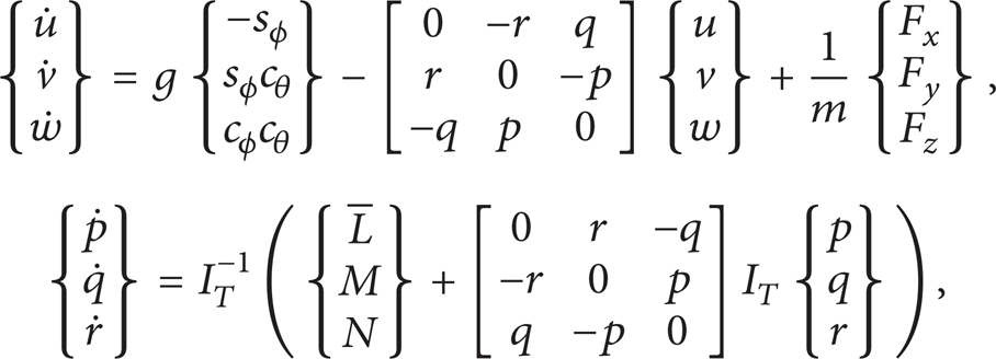
This UAV can be modeled as a rigid body, and undergoes three-dimensional motion described by three inertial position coordinates and three Euler angles. Hence, 12 state variables are required to describe motion of the UAV at a given instance in time [18]. In the equations below, the ground frame is assumed to be a satisfactory reference frame. Besides, the earth is assumed to be flat and wind is stationary. Kinematic translational and differential equations of motion for the general system are provided by

The common shorthand notation for trigonometric functions is used throughout the paper (sin (a) = s
a
, cos (a) = c
a
, tan (a) = t
a
). The matrix

The force and moment differential equations are represented in
where
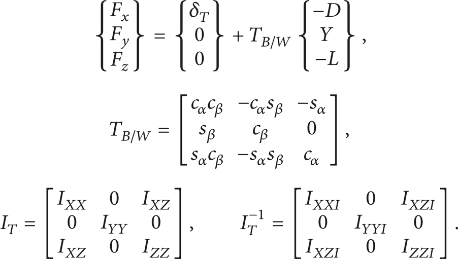
The matrix
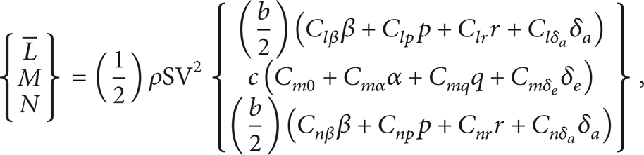
The aerodynamic forces are expressed as:

Similarly, the aerodynamic moments are described as follows:
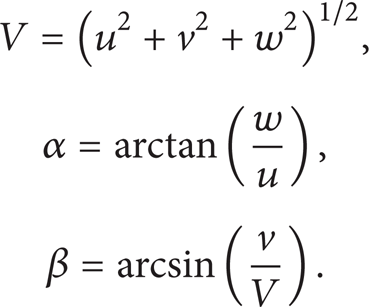
where the velocity and aerodynamic angles are defined as
The UAV model uses two control surfaces elevator and aileron. The vertical tails are fixed on the UAV and cannot be used as control surface.
3. Explicit Nonlinear Model Predictive Control Law for the Saucer-Shaped UAV
3.1. Explicit Nonlinear Model Predictive Control
For simplicity, a nonlinear MIMO system can be described by
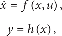
where x ∈ ℝℝ m , u ∈ ℝ n , y ∈ ℝ n are state, input and output, respectively. For a nonlinear MIMO system, it is generally known that each control will appear after a specific number of derivatives of the output [19]. The relative degree ρ i is the number of time derivatives of the ith output needed for control to appear. If continuously differentiating the output after the control input appears, time derivatives of control will appear and the number of the input derivatives r is defined as control order. The ith output of the system in the receding horizon can be approximated by its Taylor-series expansion up to order ρ i + r:

where i = 1,2, …, n. For each channel in the output matrix, the control orders r are the same for each vector in the output matrix and can be decided during the control design, but the relative degrees ρ i are different and determined by the specific model structure. The approximation of the entire outputs can be described in a matrix form as follows:

To simplify the calculation, we change the order of the variables in (10) and separate the terms without control input from the remaining terms. Therefore,

where

According to the equations shown above, we now can construct matrix

where the nonlinear terms L f ρ i h i (x), i = 1,2, …, n are parts of ρ i th time derivatives of the ith output without control input. By differentiating (13) with respect to time, we can get

and p1(x, u) is a nonlinear vector function of state and input. The higher derivatives of the output and

In the same as (10), the desired output signal w(t) can also be appropriated as follows:
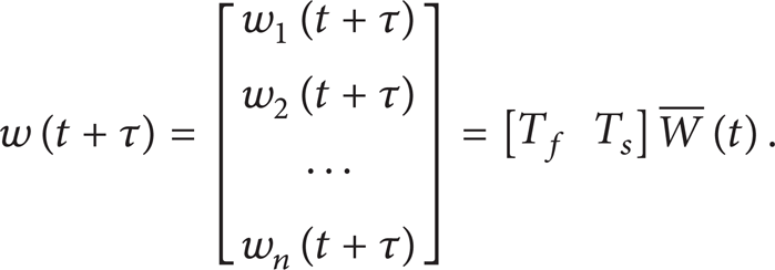
The construction of
Expanding the input in a similar way we have
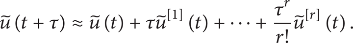
Thereby, the outputs can be decided by the control variables
To any control problems, we hope that the output y(t) follows the prescribed reference w(t) well. Therefore, the control law can be achieved by minimizing a receding horizon performance index:

where the weighing matrix


Instead of minimizing the performance index in (18) with respect to control profile u directly, we can minimize the approximated index J in (19) with respect to

The optimal control variables
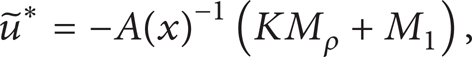
where

In order to obtain the control signals, conventional MPC algorithm needs to solve an optimization problem at each sampling instant. The ENMPC method can effectively avoid the computationally intensive online optimization and shows better control effects [20].
3.2. Saucer-Shaped UAV Control Law
To control an aerial vehicle by this ENMPC method, we choose Euler angels as outputs. From the special shape of this UAV, we can conclude that the yaw dirigibility is not as good as conventional ones. Besides, with the absence of a rudder, the yaw motion can only be achieved by manoeuvring the roll direction. Since in this method the number of outputs needs to be equal to the number of control inputs, we determine
After the first derivatives, we can obtain

The ENMPC method requires the output equations to be differentiated until the control inputs appear. From the model of the UAV, we perceive that the control inputs appear in

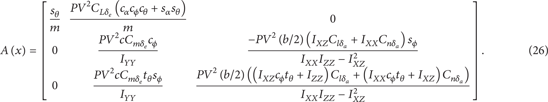
Therefore, the relative degree for each input is 2, and the matrix A(x) in (13) can be described as
Therefore, when the desired fight attitude of the UAV is determined, we can get the desired output

Thus, the resulting controller can be calculated by (22). The control structure can be shown in Figure 2.

ENMPC structure for the saucer-shaped UAV.
4. Simulations Results
The main purpose of this simulation is to prove the practicability and check the performance of the ENMPC strategy on a lifting-body UAV. There are two simulations conducted in this section. The first one aims at verifying the control effect in both longitudinal and lateral directions. The other one is conducted under longitudinal wind disturbance to evaluate the robustness of the control law. The model for the simulations is the one introduced in Section 2. For comparison, a PID controller is employed. In the PID method, we also use the model given in Section 2. Then, the nonlinear equation of motion is linearized on the condition of little perturbation around the equilibrium point and divided into longitudinal and lateral equations. The control law is obtained according to the linear equation and applied to the UAV [21]. The preceding system of equations describing the UAV is numerically integrated using a fourth-order Runge-Kutta algorithm. In the following results, the control derivative is updated every 0.005 s. The thrust provided by the engine used on the UAV is no more than 500 N. The elevator and aileron are limited between −20 deg to 20 deg. In order to be more close to the practical situation, the rate of change for each control surface is limited to −20 deg/s to 20 deg/s. Tables 1, 2, and 3 list characteristics of the UAV used for the simulation, including dimensions, mass properties, and aerodynamic derivatives. Stability derivative values were taken by a series of static and dynamic derivative wind tunnel tests.
Dimensions and mass properties of the saucer-shaped UAV.

Longitudinal aerodynamic derivatives of the saucer-shaped UAV.

Lateral-directional aerodynamic derivatives of the saucer-shaped UAV.

Figure 3 shows the 3D view of the control results by different control strategies. In the PID method, the UAV's longitudinal and lateral equations are decoupled around an equilibrium point, and the control law is given by respective linearization. In these techniques, the linearization is restricted around the equilibrium point, and mainly the stability property is considered and little insight into other aspects of dynamic behaviour is provided [22]. But the ENMPC strategy can give a strong relationship between each variable. Therefore, it can keep the height stable even when the lateral maneuver appeared, but a descent will arise when using PID control law, which is obvious in Figure 4. That means the UAV track is smoother when using ENMPC compared with PID. The outputs are approximated with a sixth-order Taylor-series expansion, and the prediction horizon is 0–6.0 s in the ENMPC strategy.

3D view of flight.

The saucer-shaped UAV height response.
Figures 5–7 show simulation results of the control signals corresponding to the trajectory in Figure 3.

Throttle behavior.

Elevator deflection.

Aileron deflection.
In PID method, throttle signal is obtained directly by longitudinal variables. However, in ENMPC strategy, it is determined by both longitudinal variables and lateral variables. Therefore, when the UAV exhibits its later maneuverability, the throttle signal is influenced by the changing of lateral variables and adjusted immediately to keep a stable flight path. In Figure 5, the changing of the throttle is more violent under the control of ENMPC strategy, which can keep other variables stable and reduces the changing of elevator signal which is obvious in Figure 6. The aileron deflection is almost the same when using the two different strategies and showed in Figure 7. Considering the special shape of this UAV, the area of the control surface is not as large as conventional airplanes. Besides, it combines the functions of an elevator and an aileron. Therefore, the ENMPC can increase the throttle signal and decrease the elevator signal which is more suitable for this kind of UAVs with small area of the control surface.
To evaluate the robustness of the control law, longitudinal wind disturbance is introduced in the simulation. Figure 8 shows the height behavior under the unexpected wind disturbances which occur separately at the twentieth and sixtieth second and with a duration of 3 seconds. The first wind disturbance has a velocity of 2 m/s and a dip angle of 20°. The second one has the same dip angle but a velocity of −2 m/s.

Height behavior under wind disturbance.
In Figure 8, when the first wind disturbance appears, height behavior has a variation of 1.14 m under PID control law which is 3 times as large as the variation under ENMPC strategy. Besides, the peak value of the dotted line arises at 23.65 second; however, when ENMPC strategy is employed, the peak value appears just right at 23 second. After the disturbance disappears at 23 second, the height behavior needs about 10 seconds to return to its initial value under PID control law which is 5 seconds longer than using ENMPC strategy. When the UAV comes across the wind disturbance at 60 second, height behavior shows a similarly change. It is obvious that ENMPC strategy has a stronger robustness compared with PID method.
Figures 9–11 separately represent the velocity, attack angle, and pitch angle behavior when wind disturbances appear.

Velocity behavior under wind disturbance.

Attack angle behavior under wind disturbance.

Pitch angle behavior under wind disturbance.
In PID method, velocity keeps a stable value from beginning to end. However, in ENMPC method, velocity decreases when the UAV comes across the updraft and increases under the downdraught. In other words, when the wind disturbance influences the aerodynamic force of the UAV, ENMPC method can adjust the velocity to bring an opposite influence. Therefore, ENMPC method has a better control effect on the flight attitude. It is obvious in Figures 10 and 11 that attack angle and pitch angle enjoy a relatively gentle change under ENMPC method compared with PID.
5. Conclusions
An explicit nonlinear model predictive control strategy was developed and simulated for a saucer-shaped lifting body UAV. As the lifting body UAV is difficult to be controlled compared with conventional ones but enjoys a wide application nowadays, designing a proper controller for special shaped UAV is a challenging but promising work. By comparing with PID strategy, ENMPC can get better controlling effect. On one hand, the control signals are calculated from nonlinear model without decoupling or linearization. On the other hand, the on-line optimisation process is removed from the MPC framework, which can accelerate the software development and simplify the onboard hardware. Due to these advantages of ENMPC, control framework has a low complexity, high reliability, and rapid response to the fast dynamic of UAVs. Besides, the throttle signal is not calculated only from velocity but influenced by all the variables. It can be adjusted immediately which reduces the deflection of the elevator. Therefore, the ENMPC strategy is more suitable for UAVs with smaller area of the control surfaces.
Our future work will focus on applying ENMPC strategy in actual flight tests using the saucer-shaped lifting body UAV. Furthermore, we are also interested in improving the control strategy to fit lifting body UAVs better.