
Abstract
Today's technologies in the IT area face the era of combination and convergence of technologies in many different areas. Through the natural interaction between people and devices in the environment where various kinds of devices are connected over a single network, they have been developing from human-oriented service technologies to smart and futuristic home technologies. Smart home technology is one of them. It is a technology of establishing a digital home in which various kinds of home appliances are connected over a home network and diverse services are provided for users regardless of time and place. Technologies in the IT area are combined with technologies in many different areas, creating and producing numerous technologies. Also, much research on smart home, the theme of this work, has actively been conducted. In this work, the use of a current booster, an AC/DC converter, and a DC/DC converter to operate electric lights; this work implements the smart power control system using standby power and RF communication, among smart home technologies.
1. Introduction
1.1. Overview of the Study
Smart home refers to a home to which various digital convergence technologies are applied in the course of changing from the analogy era to the digital era. Today, regardless of place and type, digital technologies are used in every part of our life. People who lived in the past analog era now experience fast changes in their life of the present digital era. For instance, cassette tapes used in the past changed to MP3, analog TVs to digital TVs, and film cameras to digital cameras. In other words, our life is gradually changing from analogy life to digital one. The fast spreading of various digital devices, in fact, is not because of the development of the time, but because of the support of technologies helping to share a variety of information on the high speed internet. Through the internet and network, we are able to control or manage various digital devices. By connecting each one of different digital devices, we can control and manage all things that have something to do with us. As a result, smart home provides us with diverse services. Figure 1 presents a consumer service environment in a smart home [1].
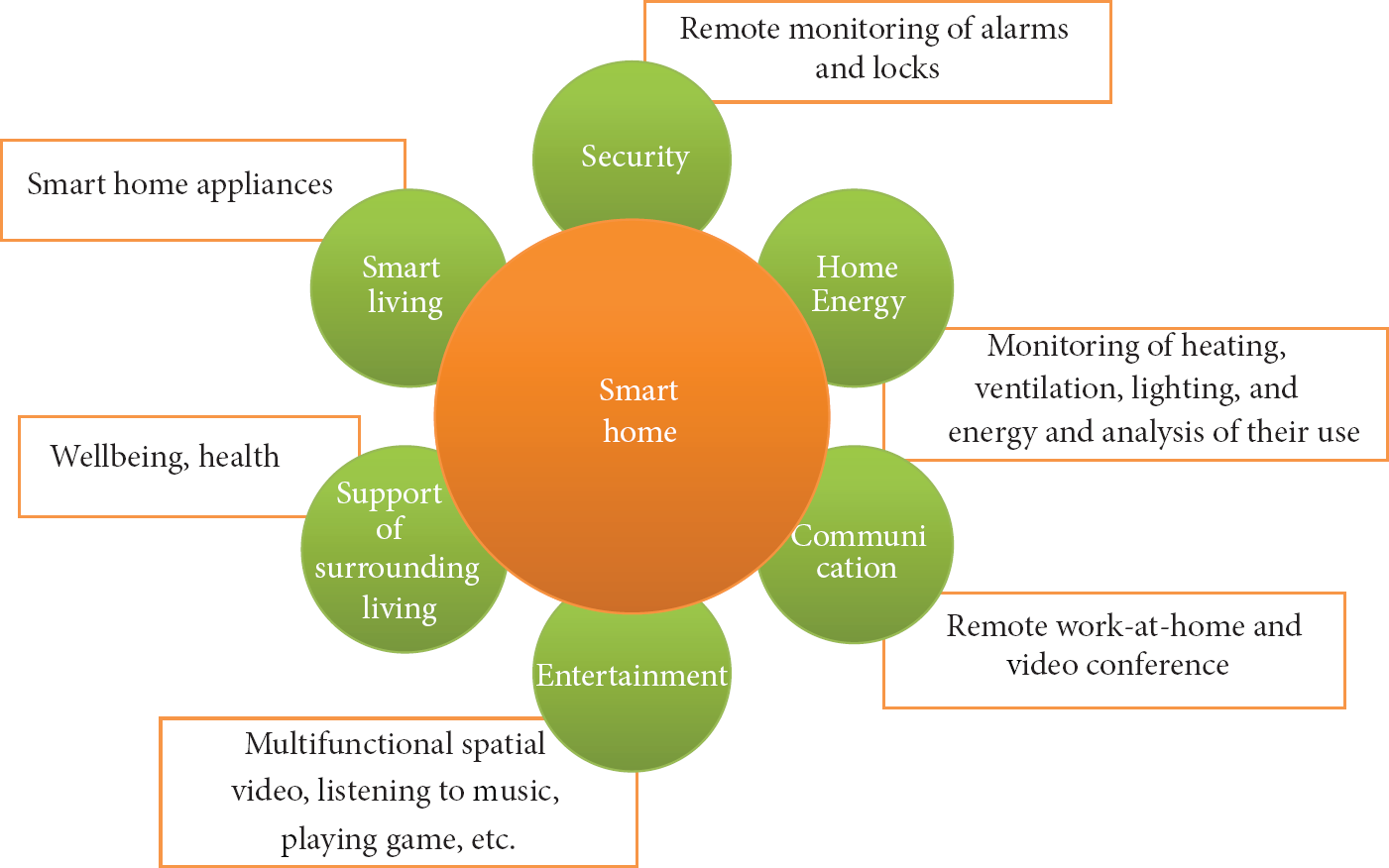
A consumer service environment in a smart home.
As shown in Figure 1, smart home includes convergence of various services, including security, health, work, energy, environment, and communication, which are connected together on a single network.
One of these technologies is u-Health. u-Health has changed by various consumer service environments and is now different from past methods. Contrary to the previous method in which a wired instrument was attached to the user's body and the user's body data was taken, the current method involves collecting the user's body data using various wireless instruments. In other words, the traditional wired network environment is not used as much as the wireless network environment. The wireless network environment enables the use of systems that include but are not limited to personal computers and smartphones. In addition to collecting the user's body data, the wireless environment helps users to manage their diet and health [2].
Technologies for collecting user data in diverse environments and providing information that is necessary to users based on the collected data are also studied [3].
Through smart home, it is possible to provide ecoenergy system service. The value of smart home is basically in the extension line of home automation, referring to a further advanced concept of it. The main features of smart home are presented as follows.
The First One Is Smart Control. It is one of important features of smart home. Smart control includes improved control ways like motion control and serves the function of remotely monitoring each state of home appliances through smartphones or tablet PCs.
The Second One Is Smart Power-Saving. Consumers pay great attention to energy-saving. Smart home appliances can help to minimize energy cost according to consumers' patterns.
The Third One Is Smart Application. Smart home provides applications suitable for the features of smart home appliances, so that it is possible to increase the usability of smart devices. In particular, home appliances with a screen like TV can expand their functions with the help of applications [4].
Smart home is in the initial stage in terms of technological development, and therefore it has yet to provide perfect implementation. For this reason, the purpose of this work is to implement a system to monitor and control a smart home at any time and place, as smart home will be popularized and interoperate with various devices.
Smart home allows various kinds of equipment and devices to get connected on a network, helps users to receive and monitor proper information at any time and place, and makes possible better quality of life through a wide range of services in everyday life.
1.2. The Necessity and Importance of the Study
With the emergence of ubiquitous and digital convergence environments, smart home contributes to an improvement in individuals' quality of life and to providing of services regardless of time and place. Thanks to the development of network technology, all information devices and home appliances are connected and controlled on a single network. The environment is called smart home.
Smart home serves the function of connecting a variety of conventional digital devices and the function of using them as if they are a single digital system by using wired and/or wireless networking technologies, such as radio frequency (RF), ZigBee, Bluetooth, and Ethernet [5].
Thanks to the fusion of IT technologies, machine to machine (M2M) communication, which has a number of meanings, has significantly changed our lives. As information collection and utilization are extended from men to machines, new services and technology have become necessary. Thus, M2M communication services have encouraged the development of a new business model for mobile communication enterprises and the smartphone industry.
M2M communication can refer to machine to machine, mobile to machine, and machine to mobile communication. M2M, also called machine intelligence communication, may mean the communication between a machine and a person, or between a device and another device. In a broad sense, M2M is the concept of networking the machines and the devices that are widespread throughout our daily lives. M2M enables us to check and control an object, system, vehicle, state of a person, and positional information from a remote place by combining communication and information technologies. M2M communication enables us to use various devices, from a computer mainframe to the daily electronic products, by connecting them with each other. For example, M2M can be applied to home electric appliances, transportation, such as a car, or a residential building. This concept enables machines or devices to transmit the desired data from a remote place through a mobile communication network or transmission media. The current concept of M2M communication is being extended to utilize various wired and wireless networks beyond the global standard for mobile communication (GSM) network. The concept is for machines or devices to transmit their own data from a remote place through a communication network, such as a mobile communication network. Various data, such as position, health status, and temperature, may be acquired through the interaction between a person and a machine. M2M is the next-generation network and will create added value by integrating the current assets of all the companies, such as an IT system, through the combination of information communication and information technology for an automated processer [6].
Although much research on the ways of connecting a variety of equipment in a smart home has been conducted, research on consumption power of each digital device just began. Implementation of a smart home brings about advantages yet causes some disadvantages, one of which is a great deal of consumption power caused by the connection of home appliances.
One of the major problems is the security problem. Security may be an issue when exchanging data among devices in an environment where various devices are combined without a standard protocol. In receiving information from a variety of devices, the data protocol and the vulnerable security areas will be attacked by hackers. In solving the security problem, the unsecured protocol and the vulnerable parts may be safely protected through message integrity, use of cipher, and personal information protection policy [7].
The degree to which data losses are minimized in wireless network environments is important in sensor networks, as the smaller the data losses, the higher the reliability [8].
Another drawback is the inefficient management of energy. This article suggests a method to solve the inefficient energy management problem.
Korea's energy consumption is dependent on overseas accounts for 97%. Along with an increase in Korea's income level, Korea as an energy dependent country sees annual rises in living energy consumption (household, commercial, etc.) and transportation energy consumption [9]. In particular, because the use of home appliances and office device leads to an increase in electric energy consumption in a home, more attention has been paid not only to the electricity amount consumed at the time of using devices, but also to the standby power consumed at the time when devices are plugged in. Annually, power consumption caused by the standby power is on the rise, accounting for about 10% of the entire energy consumption in a home [10]. Therefore, it is necessary to recognize the circumstance and develop a system to reduce the standby power. Accordingly, in designing smart home service, this work tries to use the standby power for other purposes and thereby provides various services in a smart home. This work tries to make an RF-based light switch controller power supply device by using quiescent current which flows in electric lights installed in each room of a house. We can block the standby power of general home appliances we use by plugging them out. But, electric lights are exceptional. A current always flows in electric lights, and as a result, the standby power consumption of electric lights used in a large factory or a public institute is very high, though that used in a house is low. This work tries to use the standby power of electric lights and implement a system that can control and turn on/off multiple electric lights at any time and place through smartphones [11].
2. Design of a Smart Power Control System
2.1. A Scenario of a Power Control System
It is assumed that the smart power control system proposed in this work is able to help users to turn on/off electric lights in a home at any time and place. For making a light switch on or off, a module to control the switch and a board with an RF module are installed. The relevant system is operated by the use of standby power. In fact, the standby power is not powerful enough to operate the system. So, this research designed the system that has multiple-trans connected in series and extracts a current from each trans. As a result, the system is operated by the currents accumulated from the trans connected in series and helps a user to control a light switch at any place of a house through RF communication. Figure 2 illustrates the scenario suggested in this work.
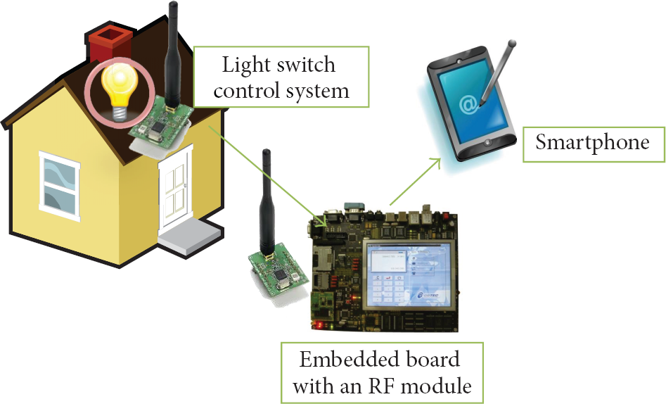
A scenario of the smart power control system proposed in this work.
In this work, data between the RF switch and the embedded board are transmitted through a CC1020 RF module, and data between the embedded board and a smartphone are transmitted over TCP/IP. Since data are gathered in real time, they can be monitored in real time, the embedded board can control an electric light in real time, and a user can control an electric light through a smartphone. The differences between the system and other conventional systems are that the system efficiently uses standby power and that the system controls a device through an embedded board, rather than a PC. Because of the use of an embedded board, the system has advantages of low price, mobility, low consumption power, and replace ability of an embedded board. Given the aspects, the system provides the environment most suitable for a smart home.
2.2. A Data Transmission Device
In this work, the data transmission device uses an RF module with CC1020 chipset. The RF module is a low power RF TX/RX module with 400 MHz. The module supports 402~470 MHz in terms of frequency bandwidth, supports 153.6 Kbps at the maximum speed, and consumes 16.2 mA at Tx, 19.9 mA at Rx, and 1.8 uA at standby mode. It is attached to a switch and an embedded board, helping to send and receive data between both devices. The reason why this work uses the CC1020 module is that the Zigbee module of CC2420 or CC2500 mostly used these days arises as an issue in terms of radio wave certification and data reliability. However, CC1020 does not require a radio wave certificate and shows the highest data reliability at 400 MHz. For this reason, it is used in this work. A microprocessor of the communication module in this work is ATmega16L. ATMega16L uses CC1020 chipset, has a communication program built in, transmits communication packets through the serial communication with MCU, and supports MAC function. It serves the function of controlling CC1020 through the communication with SPI and DIO. The CC1020 used in this work have advantages of a small size, low battery consumption, and a wide range of RF signal strength.
2.3. The Equipment for the Control of the Smart Power Control System
For the control of the smart power control system, an imbedded board, instead of a conventional personal computer, was employed. An imbedded board is cheaper than a personal computer and easy to move and install, and it is possible to replace a module when there is a problem. Additionally, an imbedded board consumes significantly less electrical power than a personal computer. Thus, it is suitable for this research project.
2.3.1. RF Data Transmission and Reception Instrument
The system employs a low power RF TX/RX module using 400 MHz band frequency. Both the frequency band of 402–470 MHz and the maximum rate of 153.6 Kbps are supported. The low-power TX/RX module consumes 16.2 mA during Tx, 19.9 mA during Tx, and 1.8 uA in the waiting mode. The module is attached to the switch and the imbedded board, respectively, transmitting and receiving data between the two devices. Figure 3 shows the picture of the RF module on which the CC1020 is mounted.

The RF module on which CC1020 is mounted.
In this study, the CC1020 module was used because the frequently used Zigbee modules, such as the CC2420 and the CC2500, have problems with electromagnetic wave certification and data reliability. However, the CC1020 does not require an electromagnetic wave certification, and the data reliability is the highest in the 400 MHz band. Hence, the CC1020 module was employed in this study. The microprocessor of the communication module is ATMega16. ATMega16L mounts communication software by using CC1020's chip set, transmits communication packets through the serial communication with MCU, and supports the MAC function. ATMega16L controls CC1020 by using the SPI and DIO communication. The advantages of the CC1020 are the small size, low battery consumption, and the broad RF signal strength width. Figure 4 shows block diagram of the RF communication module.

Block diagram of the RF communication module.
2.3.2. RF Data Message Information
The data sheet of the RF module used in this study is shown below. Different from the serial communication using the conventional Zigbee, the data sheet allows for a convenient checkup of the results. Thus, the messages do not need to be integrated and presented as a new message. The resulting values can be derived on the basis of the command values and the data values of the command.
(A) Communication Method
Communication PORT: composed of DCLK [Input] and DIO [OutPut] (General-purpose IO, Serial input and output data bus clock). DATA composition: one time preamble data composed of 8 bytes as shown in Figure 10:
preamble: one time, CMD: COMMAND, DATA: SUB DATA for the COMMAND, serial number: to distinguish the equipment, CHECK SUM: (serial number ∧ layer ∧ DATA1 ∧ ID), transmitted by the imbedded board and responded by the switch. (retransmission is tried if there is no response within 200 ms), considers the maximum 30 lamp switches.
The transmission timing is synchronized among the RF modules by using the preamble signal. Thereby, the system information transmission is started at a predetermined timing. After receiving the preamble signal, the RF module transmits the CMD, serial number, Data 1, and Data 2 information. The maximum number of the provided lamp switches is 30.
(B) Command. The communication information between the imbedded board and the switch controller mounted on a lamp is summarized below. Table 1 shows communication information from the imbedded board to the switch. Table 2 shows communication information from the switch to the imbedded board.
Communication information from the imbedded board to the switch.

Communication information from the switch to the imbedded board.

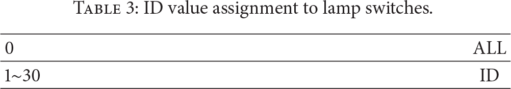
ID Assignment. There are about 10 to 20 lamps in a household. Therefore, the maximum number of lamp switches provided in this study was set to 30. Table 3 shows IDs were assigned to the lamp switches.
ID value assignment to lamp switches.
2.4. Design of the Main Program
The main program was written using C# development language provided by MS (Microsoft). The C# language was used to realize the main program because the scenario of this study does not have a separate server. Thus, the imbedded board simultaneously plays the role of a client and a server. The original purpose is to manage, share, and save data by means of a server, but no separate server is needed because the purpose is to actuate the lamp switches. Therefore, the main program was designed using the C# programming language, which has excellent memory management and provides various functions in an internet environment. The platform of the imbedded board platform is based on WinCE 6.0. The RF sensor in the lamp switch controller is always turned on, waiting for the data request from the imbedded board. When a data request comes in, the RF sensor sends the current status information (CMD, serial number, and data information) to the imbedded board, which then receives the information and processes the received information so that it can be monitored on a screen. The information can be monitored with a smartphone; a smartphone is also able to turn the lamps on and off. (Figure 5 shows inner action of the main program.)

Inner action of the main program.
3. Implementation
3.1. Implementation of a Light Switch by the Use of RF Communication
It is a device to supply power to an electric light through radio frequency (RF). More specifically, it is an RF switch drive system to control the power of electric lights in and out of a house through RF. Before power supply, the system converts an alternating current into a direct current. The RF switch controller turns on/off an electric light through RF communication with the RF module built in an embedded board and receives power by the use of standby power. The current booster of the switch controller, which serves as a role to boot a microcurrent to a high current and rectify into a direct current, saves a microcurrent when a switch is off and communicates through RF by the use of the saved microcurrent or standby power when a switch is on. The current booster, a set of more than 20 trans, gathers and saves standby power. Figure 6 shows a diagram of the standby power RF light switch system [12].
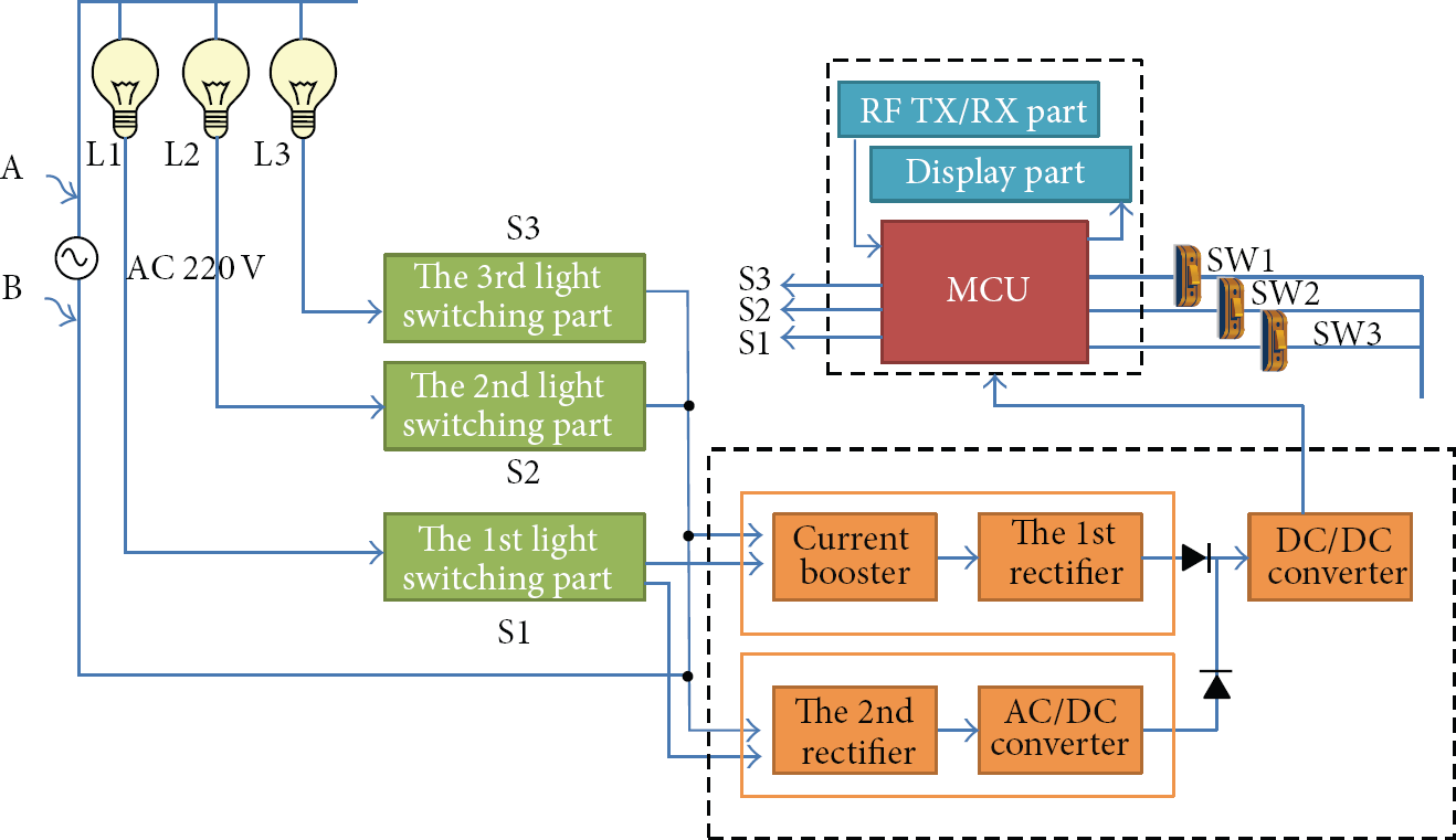
A diagram of the RF light switch system.
3.2. Implementation of a Monitoring System
The main program installed into the embedded board (Mango 310) provides a communication environment to monitor the current light state and make access through a smartphone. Figure 7 shows illustrates a window of the main program. When a user enters an IP address and a port number and clicks Access button, the user can have access at any time through a smartphone. By looking at the data log, a user can check a current ID value, a command value, and the state of lights.
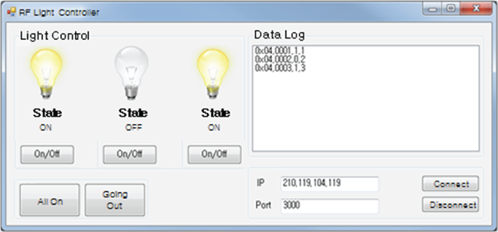
A window of the main program.
In addition, a user can check the state of lights in the type of images in real time and turn on/off lights by using the on/off option.
If an electric light is turned on, the main program shows the state of the light as a turn-on image and displays each value of CMD, ID, and DATA1 on the data log section. Also, on the option section of the main program, there are two buttons: All On and Going out. When All On button is clicked, all lights are turned on, and when Going out button is clicked, all lights are turned off. When a user enters an IP address and a port number necessary to make access from outside on the Set-up section and clicks Access button, the user can access the embedded board to control electric lights at any time through a smartphone.
3.3. Implementation of a Smartphone Application
The smartphone application is used for a user to control electric lights at any time and place through a smartphone.
When an embedded board opens a communication port and sets up an IP address, a user can have access to the embedded board through the IP address and communication port by using the application program. Figure 8 shows the main screen popping up first when the smart power control application runs.

Screens of the smart power control application.
When a user enters an IP address and a port number on the main screen and clicks Access button, the user can access an embedded board. As shown in the next screen, the state of electric lights in a house is displayed. On the screen, a user can turn on/off the lights.
4. Examination and Evaluation
To evaluate and analyze the smart power control system implemented in this work, this research made some preparation as shown in Figure 9 and began to evaluate the system.

Smart power control system architecture.

The system was tested on the basis of the whole scenario. The control of electric lights was tested in each embedded board and smartphone environment. To make access through a smartphone, an IP address and a port number were assigned to an embedded board. After that, the given IP address and port number were entered in a smartphone for access. Turning on/off electric lights was tested in each embedded board and smartphone environment. And it was found that the embedded board and smartphone worked well. In the case of smartphone control, one problem was that it took different time to turn on/off electric lights depending on the wireless interest speed. It is a technical issue, so that it seems to be solved through the change of an IP address sharing router or through the change of the internet line. To investigate how much the RF controller of an electric light switch uses standby power with the naked eye, this research attached a watt meter to the controller and measured standby power. The electric lights did not consume electricity apparently. When an electric light was off, a microcurrent flowed in the light. The test of the system revealed that the microcurrent was supplied to RF devices. The supply of a microcurrent is the core technology of this work.
As seen earlier, electric lights were controlled through the use of an embedded board and a smartphone and therefore were successfully turned on/off. In addition, since the system supplied power to each RF device by using the standby power flowing in electric lights, any additional power consumption didn't occur. As a result, it was found that invisible standby power was remarkably used, and thus this work suggested that the system is able to control electric lights in a house at any time and place.
5. Conclusion and Future Research
This work developed the smart power control system to turn on/off electric lights through the use of RF communication, an embedded board, and a smartphone and showed the results of the system. In the past, a user controlled various home appliances including electric lights through wired communication rather than wireless communication. However, today, with the development of wireless communication, a user is able to control home appliances at any time and place.
By suggesting the service to control electric lights regardless of a user's location, this work provided an example of the service to monitor various kinds of indoor lights used in a home network, a factory, a commercial building, and others. Also, it proposed the service to induce users to save energy, which helps them to control electric lights.
Additionally, this work designed the system called current booster with multiple-trans to use invisible standby power. It used the current booster to operate an RF module for wireless communication.
Since the proposed functions work well, it would be possible to have an RF module built in home appliances in the future, and therefore a user could control the home appliances at any time and place through a smartphone or an embedded board by registering each ID value of home appliances.
The smart power control system developed and implemented is a prototype. Therefore, it is required to check whether the system would be applicable to actual home appliances. Also, it is needed to test safety when the system is applied to gas valves, door locks, and devices other than electric lights. In the future, this research plans to apply an RF module to home devices basically installed in a house, such as gas valves or door locks, and to control the devices. In addition, by adding more smart services, checking whether a user is at home through various sensors, accumulating information on the basis of a user's pattern, applying such information to an algorithm, this work will continue to be performed in order to improve users' quality of life.
Footnotes
Acknowledgment
This study was conducted as part of research for the 2013 Copyright Technology Development Project by the Ministry of Culture, Sports, and Tourism and Korea Commission.