
Abstract
This paper presents a new approach for quick identification of chatter stability lobes with discretization method. Firstly, three different kinds of stability regions are defined: absolute stable region, valid region, and invalid region. Secondly, while identifying the chatter stability lobes, three different regions within the chatter stability lobes are identified with relatively large time intervals. Thirdly, stability boundary within the valid regions is finely calculated to get exact chatter stability lobes. The proposed method only needs to test a small portion of spindle speed and cutting depth set; about 89% computation time is savedcompared with full discretization method. It spends only about10 minutes to get exact chatter stability lobes. Since, based on discretization method, the proposed method can be used for different immersion cutting including low immersion cutting process, the proposed method can be directly implemented in the workshop to promote machining parameters selection efficiency.
1. Introduction
Machining chatter is an undesirable phenomenon that not only reduces the surface finish quality of the workpiece but also shortens the cutter life. It is one of the most severe limitations for productivity in milling operations. To improve machining quality and productivity, it is the fundamental base for optimizing the machining process to predict the chatter stability lobes efficiently and accurately [1–3].
To predict machining stability associated with regeneration chatter, different models have been developed, such as frequency method [4, 5] and numerical method [6–8]. Altintas et al. developed an analytical, frequency-domain solution; they used zero-order Fourier series expansion to approximate time-varying directional coefficients, and an eigenvalue solution was used to solve the critical depth of cut. This method is able to predict stability lobes at a fraction of the computational expense. This method has been extended to ball-end mills [9] and variable-pitch cutters [10, 11]. Later, Merobl and Altintas developed multifrequency solution which considers the harmonics of time-varying milling coefficient and it can get accurate stability lobes for low immersion milling [12].
The stability of milling process can also be modeled in the time domain with time-delay differential equations. Insperger and Stépán [6, 7] introduced a semidiscrete time domain method to predict the chatter stability in milling process. The authors use a series of piece-wise autonomous ordinary differential equations to approximate the delay term of a time-delay differential equation. It allows the stability to be identified by using linear solution methods. Henninger and Eberhard [13] analyzed the computational efficiency of the semidiscretization method for periodic delay-differential equations. They proposed a predefined nonequidistant discretization scheme to reduce computational cost and increase accuracy of the method. Recently, Ding et al.[9, 14, 15] improved the discretization method and get more higher computing efficiency, and their method can be used for simultaneous prediction of stability and surface location error in low radial immersion milling. The discretization method tests every group set of spindle speed and cutting depthwhether to deter the milling system is stable or not.
Although the improved method can get high computational efficiency, it still needs tens of minutes or hours to get a stability lobe, which is unbearable in the workshop. In this paper, an approach for efficient identification of chatter stability lobes with discretization method is presented. Section 2 presents the basic procedure of chatter stability identification and Section 3 presents the method proposed. Validation and comparison of the presented method with the existing one are given. In Section 5, conclusions are presented.
2. Basic Procedure of Chatter Stability Identification
Without loss of generality, the dynamics of the milling process can be described by a second-order differential equation in the following form:

where M, C, and K represent the modal mass, modal damping, and modal stiffness separately.
The first step to solve (1) is to discrete the time period T into m small time intervals such that τ = m𝒯, where m is an integer. LettingQ k = Q(k𝒯), in one time interval k𝒯 ≤ t ≤ (k + 1)𝒯, (k = 0, …, m), the solution for the time-varying state equation with initial condition Q k = Q(k𝒯) can be expressed as follows:

Then at the moment t = (k + 1)𝒯, the following equation is valid:

The above equation contains time-delay item Q(k𝒯 + 𝒯 – ξ – τ), state item Q(k𝒯 + 𝒯 – ξ), and time-periodic items

where
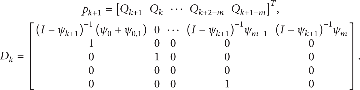
Then in one time period

The transition matrix Φis defined by

According to the Floquet theory, if the moduli of all the eigenvalues of the transition matrix Φ are less than unity, the system is stable. Therefore, the stability of the milling system can be determined by the eigenvalues of the transition matrix. Detailed derivation can be found in [8].
3. Efficient Identification of Chatter Stability Lobes with Discretization Method
According to the above procedure, the discretization method has to test each group set of spindle speed and cutting depth to determine whether it is stable or not, which is very time-consuming. While analyzing the profile of the chatter stability lobes, it shows that a large number of sets of spindle speed and cutting depth are far away from the stability boundary. If these sets of spindle speed and cutting depth are extracted first and not tested with the above method, processing time will be shorten dramatically. With this in mind, the chatter stability lobes can be divided into three regions: absolute stable region, valid region and invalid region, as shown in Figure 1. The absolute stable region is the unconditionally stable region, which means that the machining system is stable for any set of spindle speed and cutting depth. As for sets of spindle speed and cutting depth in valid region, every set has to be tested; for sets in invalid region, any set is unstable; there is no need to test.

Three different regions in chatter stability lobe.
The procedures for identification of chatter stability lobes with the presented three regions are as follows.
Identify the absolute stable region first; sets of spindle speed and cutting depth within this region will not be tested. In order to identify the absolute stable region boundary efficiently, the golden section search method combined with discretization method is used in this paper. The flow chart is shown in Figure 2. Parameters a andb indicate the preset minimum and maximum cutting depth and c and d are temporary variables. Figure 3 shows the calculated absolute stable region boundary.
Test sets of spindle speed and cutting depth out of the absolute stable region with large time interval. This step will divide the remaining region into valid regions and invalid regions within reasonable short time, and rough stability boundaries can be obtained.
For valid regions, test every set of spindle speed and cutting depth to get the refined stability boundary.

Flow chart for determining absolute stable region.

Absolute stable region.
The highlights of the proposed method are the following. (1) By dividing the whole region into different regions, stability test of spindle speed and cutting depth is not necessary for every set, and only sets within valid region shall be tested. It saves a lot of calculation time compared with the existing time-discretization method. (2) With this method, it will not lose calculation accuracy compared with the existing time-discretization method.
4. Validation and Discussion
In order to verify the method presented in this paper, computing time comparison is presented below. The computer configuration is CPU: Intel Core Duo CPU E7400 @2.80 GHz 2.79 GHz, RAM: 3.0 GB. The cutting tool used here is flat end mill, the radial cutting depth is 5mm, and the milling type is down milling. Cutting tool parameters are listed in Table 1.
Cutting tool parameters.

Computing time between full discretization method [8] (FDM) and proposed method with different time intervals is listed in Table 2. The computing time of FDM is 6555.88 s, while the computing time with proposed time is less than 720 s.
Comparison of computing time.

Shown in Figures 4 and 5 are the computing results with the method proposed in this paper. The red vertical lines in the figure indicate the valid regions. From the third step we can see that the refined process only test sets of spindle speed and cutting depth near the stability boundary so as to effectively shorten the computing time of stability boundary. In addition, in the first two steps of the proposed method, stable islands or unstable islands caused by tool helix can also be captured and thus it will not lose important stability regions.

Chatter stability lobes (100 × 10).

Chatter stability lobes (200 × 20).
5. Conclusion
This paper presents a new approach for quick identification of chatter stability lobes with discretization method. The proposed method divided the stability lobe into three different kinds of regions first; then only valid regions are finely calculated to get the exact stability boundary. With the proposed method, significant reducion of computation time is achieved. It can be directly implemented in the workshop to promote machining parameters selection efficiency.
Footnotes
Acknowledgments
This work was sponsored by the National Basic Research Program of China (no. 2013CB035802), China Postdoctoral Science Foundation (no. 2012M521804), and the 111 Project (no. B13044).