
Abstract
The Tire Pressure Monitoring System (TPMS) displays the state of a tire on a display to inform a driver of the relevant information, by means of a sensor installed on the tire of the vehicle. When the data measured from the tire are wirelessly transmitted to a receiving antenna located in the center of the vehicle, the exact transmission of data is affected by the interference from various external electronic and electrical devices. In this paper, we suggest a minimum variance distortionless response (MVDR) beamformer based on the angle-of-arrival (AOA) vector for suppressing external interference and receiving accurate data. Although the MVDR beamformer effectively suppresses the interference, it has high computational complexity because of the calculation of an autocorrelation matrix. In order to address this issue, we also suggest a generalized sidelobe canceler (GSC) beamformer which does not have the same performance of the interference suppression to MVDR but also has low computational complexity. Since the signal from each tire can cause interference to others, we consider utilizing a unique Gold Code to each tire to minimize intertire interference and reduce power consumption of a battery installed in each tire.
1. Introduction
If air pressure of a tire is too high or low compared with a reference pressure, it is likely to cause a serious accident. The TPMS is a system for measuring the temperature and pressure of each tire by means of the installed sensor to transmit the measured data to the central processing unit (CPU) in the vehicle in order to prevent the accident [1–3]. The TPMS sensor unit (SU) installed on each tire transmits the data measured in real time to the driver's console to enable the driver to check tire pressure and temperature. Since the TPMS transmits and receives data through wireless communication between the transmitting antenna on the tire and the receiving antenna in the center of the vehicle, the transmission module installed on the tire needs a battery for supplying power, and it is thus currently required to develop compact battery technology and the technology for prolonging the life span of the TPMS through a low-power consuming device [4–7]. Since TPMS wirelessly transmits data from SU installed in tire of a vehicle to CPU installed in the center of a vehicle, it is the typical example of the machine-to-machine communication system.
Since September, 2007, it is compulsory to install the TPMS on vehicles produced in the USA and imported from other countries by the act on compulsory TPMS installation in the USA [8]. The EU is promoting an act for compulsory installation of the TPMS on vehicles from 2012 to 2014. The Korean government is also promoting enforcement of compulsory installation of the TPMS on vehicles since 2013, and the introduction and development of vehicle safety devices in addition to the TPMS are underway in Korea. The TPMS uses communication frequency of 433.92 MHz in the USA and Europe and 433.92 MHz and 447 MHz in Korea [9]. The interference signal with the high power from external devices should interfere with exact transmission and reception of the TPMS data. For suppressing such interference, we suggest AOA vector-based MVDR beamformer with excellent performance. While the precedent switch beamforming technology [10] cannot create null in the AOA direction of interference, which results in the low performance for the interference suppression, the MVDR beamforming technology creates null in the relevant AOA to implement highly effective performance of interference suppression. However, the MVDR uses the autocorrelation matrix, which results in very high complexity. In order to address this issue, the generalized sidelobe canceler (GSC) beamforming technology is also suggested in this paper. While the GSC beamforming technology has similar performance of interference suppression to the MVDR beamformer, its complexity is significantly low [11]. For applying the beamformer suggested in this paper to the TPMS, a transmission antenna and a sensor are installed in each tire, and M antennas are arranged in the center of the vehicle in a line. In this paper, we also consider utilizing the unique Gold code [12] given to each tire in order to suppress interference caused by transmission signals of other tires.
This paper is organized as described below. Section 2 defines a received signal model which includes TPMS signals, interference signals, and additive white Gaussian noise (AWGN). Section 3 describes the suggested beamformers for suppressing TPMS interference signals. Section 4 describes a method of calculating the complexity of the GSC and the MVDR beamformer. Section 5 examines the performance of beamformers suggested in this paper, including beamformer complexity, output signal-to-interference and noise ratio (SINR), and beam patterns, by means of computer simulation. Finally, the conclusion is given in Section 6.
2. Received Signal Model
For applying the beamformer suggested in this paper to the TPMS, M antennas are arranged in a line in the center of the vehicle in order to receive data from each tire as shown in Figure 1. Based on the uniform linear array (ULA), the received signal at the sample index k is given by

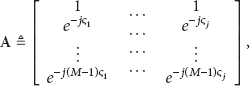
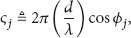

Transmission/Reception antennas in the vehicle for beamformer applied to TPMS.
SINR [16] of the beamformer output, used in computer simulation, is given by

3. Beamformer for Wireless Communication of TPMS
The TPMS wireless communications for the accurate data transmission suffer from various external devices. In this section, the beamforming technology is suggested for the TPMS receiver with the high performance of the interference suppression for accurately receiving the desired signals.
3.1. MVDR Beamformer for TPMS
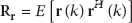
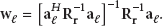
A beamformer shown in Figure 2 calculates a weight vector for minimizing the power of the beamformer output while maintaining the power of the desired signal, by using the AOA vector of the desired signal. The AOA of the TPMS signal can be determined when the TPMS is installed in a vehicle. The MVDR weight vector based on AOA is calculated by [17]


AOA vector-based MVDR beamformer architecture.
This output
3.2. GSC Beamformer for TPMS
Although the MVDR has excellent performance of the interference suppression, it has high computational complexity due to the calculation of an autocorrelation matrix. In order to address this issue, in this paper, we suggest a TPMS receiver based on GSC beamformer, shown in Figure 3. The GSC beamformer has similar performance of interference suppression to that of MVDR, and it also has low computational complexity compared to MVDR because it does not require autocorrelation matrix calculation. The GSC weight vector is calculated based on the adaptive algorithm like the least mean square (LMS) algorithm. The LMS algorithm is robustness to the environmental change and it has simple equation form which results in simple calculation.

Structure of GSC beamformer based on LMS.
The LMS weight vector of GSC is given by [23, 24]


In (10),


3.3. Gold Code for TPMS Signal
The signal from other tires in different directions acts as interference when receiving data from a uniform direction. In order to suppress the interference from other tires and to reduce the consumed power, the Gold code with the length of N is employed to each tire. A unique Gold code (length N) is given to each tire to transmit data. The transmitted signal is spread by means of the Gold code in SU, and the received signal is despread by means of the same Gold code in CPU located in the center of a vehicle to detect the desired data. The despread signal is given by


4. Computational Complexity of Beamformer
In this section, we describe a method of calculating the complexity of the proposed TPMS beamformers to compare and analyze the performance of the computational complexity of each beamformer.
4.1. MVDR Beamformer
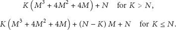
The temporal average used to calculate the autocorrelation matrix required for beamforming of MVDR is defined by

4.2. GSC Beamformer
In consideration of complexity calculation for the GSC beamformer, the number of multiplication/division and addition/subtraction to obtain


5. Computer Simulations
In this section, the results of computer simulation are described to verify the performances of the proposed beamforming technologies.
5.1. Computer Simulations for Computational Complexity
For computational complexity simulation of two TPMS beamformers, the complexity of multiplication/division and addition/subtraction of each beamformer is considered. The results are compared through complexity simulation of each beamformer for variables M, N, and K. Figures 4 and 5 show complexity comparisons of multiplication/division and addition/subtraction, respectively, depending on the number of samples for convergence, assuming that the length of the Gold code is

Comparison of computational complexity via number of samples for convergence.
Comparison of computational complexity via number of samples for convergence.
Figures 6 and 7 show complexity comparisons of multiplication/division and addition/subtraction, respectively, depending on the length of Gold code, assuming that

Comparison of computational complexity via length of Gold code.

Comparison of computational complexity via length of Gold code.
5.2. Computer Simulations for Interference Suppression
For the computer simulation, we consider two cases with four and six receiving antennas in the center of the vehicle. The incidence angles of the TPMS transmission signal from each tire to the receiving antennas are assumed 60°, 120°, 240°, and 300°, respectively, and the number of the Gold code is
Figure 8 shows the beam patterns of the MVDR beamformer with four receiving antennas. In Figure 8(a), the MVDR forms two beams to 60° (right front) and 300° (left rear) direction, and it created nulls for three directions of 87°, 165°, and 268°, at the same time. Similarly, we can find two beams for 120° (right front) and 240° (right real) directions and three nulls for 87°, 165°, and 268° in Figure 8(b). Figure 9 shows the beam patterns of the GSC beamformer with four receiving antennas. It is seen that the GSC beam patterns in Figure 9 are very similar to the beam pattern of MVDR. Figures 8 and 9 show concurrent beamforming for the front tire and the rear tire directions, because the beam is simultaneously formed at angles of ϕ and

Beam pattern of MVDR beamformer with four antennas. (a) Beam pattern for right tire TPMS signals with 60° and 300° incidence angles. (b) Beam pattern for left tire TPMS signals with 120° and 240° incidence angles.

Beam pattern of GSC beamformer with four antennas. (a) Beam pattern for right tire TPMS signals with 60° and 300° incidence angles. (b) Beam pattern for left tire TPMS signals with 120° and 240° incidence angles.

Beam pattern of MVDR beamformer with six antennas. (a) Beam pattern for right tire TPMS signals with 60° and 300° incidence angles. (b) Beam pattern for left tire TPMS signals with 120° and 240° incidence angles.

Beam pattern of GSC beamformer with six antennas. (a) Beam pattern for right tire TPMS signals with 60° and 300° incidence angles. (b) Beam pattern for left tire TPMS signals with 120° and 240° incidence angles.
Figures 12, 13, and 14 show the simulation results for the output SINR of the MVDR and GSC beamformers with four and six antennas and without a beamformer, with respect to SNR for

Output SINR performance of MVDR and GSC beamformers with four and six antennas and without beamformer
Output SINR performance of MVDR and GSC beamformers with four and six antennas and without beamformer

Output SINR performance of MVDR and GSC beamformers with four and six antennas and without beamformer

6. Conclusion
As more vehicle accidents occur, research on auxiliary safety devices are underway across the globe to prevent the accidents. The TPMS is designed to prevent the vehicle accident due to the abnormal tire air pressure in advance and to reduce greenhouse gas discharged from vehicles and fuel consumption. Since TPMS utilizes wireless communication technology, the serious interference occurs from the external electrical and electronic devices using the similar frequency to the TPMS frequency. The switching beamformer with the low computational complexity does not have excellent performance of the interference suppression because it does not create null to the AOA direction of the interference signal. In this paper, we suggested an MVDR beamformer for TPMS, which has excellent performance of interference suppression. Although the MVDR beamformer has excellent performance of the interference suppression, it has very high computational complexity due to the calculation of an autocorrelation matrix. In order to overcome this drawback, we also proposed a GSC beamformer for the TPMS, which has similar performance of interference suppression to that of the MVDR and does not require calculating the autocorrelation matrix to result in the relatively low computational complexity. Through computer simulation results, we verified that the TPMS GSC beamformer has better performance compared with the TPMS MVDR beamformer if the GSC weight is closely converged to optimal weight vector, because interference suppression performance of GSC is comparable to that of MVDR and its computational complexity is lower than that of MVDR. Currently, we are investigating the hybrid TPMS beamformer based on a switching and MVDR beamformers for selecting an efficient algorithm depending on circumstances in order to suppress the interference signals.
Footnotes
Acknowledgments
This research was supported by the Basic Science Research Program through the National Research Foundation of Korea (NRF) funded by the Ministry of Education, Science and Technology (no. 2012-0008837). This research was supported by the Basic Science Research Program through the National Research Foundation of Korea (NRF) funded by the Ministry of Education, Science and Technology (no. 2011-0024811).