
Abstract
Subgrade bears both the weight of superstructures and the impacts of running trains. Its stability affects the line smoothness directly, but in situ testing method on it is inadequate. This paper presents a railway roadbed in situ testing device, the key component of which is an excitation hydraulic servo cylinder that can output the static pressure and dynamic pressure simultaneously to simulate the force of the trains to the subgrade. The principle of the excitation system is briefly introduced, and the transfer function of the closed-loop force control system is derived and simulated; that, it shows without control algorithm, the dynamic response is very low and the following performance is quite poor. So, the improvedadaptive model following control (AMFC) algorithm based on direct state method is adopted. Then, control block diagram is built and simulated with the input of different waveforms and frequencies. The simulation results show that the system has been greatly improved; the output waveform can follow the input signal much better except for a little distortion when the signal varies severely. And the following performance becomes even better as the load stiffness increases.
1. Introduction
Subgrade is the basis of high-speed railways; it not only withstands the weight of the upper structures and the trains, but also the trains' repeated impact [1, 2]. The former is the static pressure for the roadbed, and the latter is the dynamic stress of the repeated changes with wheels' movement. Therefore, its stability is very significant, and it affects directly the smoothness of the superstructures; thus, it concerns the life and property safety of passengers [3, 4].
Generally, the main methods for researching the dynamic effects to the track bed by high-speed trains are numerical simulation, laboratory testing, and in situ testing. While numerical simulations and laboratory tests may be appropriate and can be performed on railroad subgrade soils sometimes, in situ testing appears to have greater application to the railroad industry [5, 6].
There are few methods for in situ testing railway roadbed stability so far. The successful application in business is only the Dynamic Stability Field Test (DyStaFiT) system of ARCADIS Company in Netherland [7]. It generates excitation force through a pair of oppositely rotary eccentric disks that drive a steel plate in periodic simple harmonic motion to simulate the loads to subgrade. Its excitation waveform is too simple and may distort, and it has poor performance of anti-interference even though its frequency is relatively high.
Aiming at the problem above, we developed a valve-controlled cylinder excitation system [8] and its control method. Through the special-designed structure, the exciting hydraulic cylinder can output static and dynamic force simultaneously in high frequency, and the exciting force and the output waveform can be adjusted online through electrohydraulic servo device controlled by adaptive model following control (AMFC) algorithm, so the system can simulate the load to subgrade and contribute to high-speed rail research.
2. Principle of Electrohydraulic Servo Excitation System
2.1. Principle
The principle of the system is showed in Figure 1. The parallel exciting servo hydraulic cylinder is the core of the system. The exciting servo hydraulic cylinder consists of a static pressure cylinder in parallel with a dynamic pressure cylinder; the static force cylinder is controlled by a proportional pressure reducing valve to imitate the constant static load; and dynamic force cylinder is controlled by a pressure servo valve (P-valve) or flow servo valve (Q-valve) to imitate the dynamic load of the train. According to the requirements, the P-valve or Q-valve can be switched to form closed-loop force or closed-loop location control system. The dynamic pressure cylinder piston rod is rigidly attached to the excitation pad and force sensor, and the static pressure cylinder piston rod end presses on the force sensor direct, thus, the force sensor is able to measure the composited output force of dynamic pressure cylinder and the static pressure cylinder.

Principle of the excitation testing system.
The requirements of the excitation servo system are as follows.
The excitation frequency is 1~40 Hz and adjustable.
When it is close-loop force control system, the output force is 200 kN ± 100 kN.
When it is close-loop displacement control system, the output displacement at 1 Hz is ±20 mm and at 40 Hz is ±0.5 mm.
Output waveforms can be controlled online.
2.2. Designing
According to the requirements, the hydraulic cylinder is designed, and some parameters calculated are showed in Table 1 [9].
The parameters of hydraulic cylinder.

3. Simulating without Correction
The electrohydraulic servo excitation system designed in this paper is a driving force control system [10]. The load can be equivalent to a mass-spring system, and as shown in Figure 2, it can simplify the static pressure force as a static interference force F L .

Excitation device srevo control loop.
3.1. Modeling
The transfer function of the servo valve is considered as second-order oscillation link because of the high natural frequency of the hydraulic load in this system:
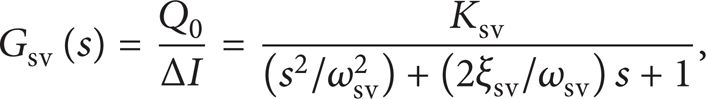
where Ksv is the flow gain of the servo valve, ωsv is the natural frequency of the servo valve, andξsv is the equivalent damping ratio of the servo valve.
The transfer function of the valve-controlled cylinder is
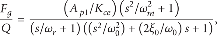
where K ce = K c + C tp is the total flow-pressure coefficient of the system, ω m is the natural frequency of the load, ω r is the corner frequency of the inertial link, ω0 is the integrated natural frequency, and ξ0 is the integrated damping ratio.
Because the response frequencies of the servo amplifier and the sensor are much greater than the system's, they can be considered as proportion link.
After analyzing and simplifying the above, the block diagram of the system could be set as Figure 3 [11], where K a is the amplify gain of the servo amplifier and K fF is the feedback coefficient of the sensor.

Block diagram of the system.
3.2. Simulating
The main parameters concerned in this paper are shown in Table 2.
Transfer function parameters of the cylinder and servo valve.

So, the open-loop transfer function of the system is

The model of the uncorrected system is created in Simulink, as shown in Figure 4. The unit step and sine signal response curves are shown in Figure 5.

The Simulink model of the uncorrected system.

The unit step and sine signal responses of the uncorrected system (a) 10 Hz, (b) 20 Hz, and (c) 40 Hz.
It can be seen that when the system is uncorrected, the unit step response is very slow and the overshoot is large; the sine signal response waveform distorts seriously and lags much, and it distorts more severely when the frequency increases. Therefore, the system cannot be used directly and should be appropriately corrected to improve the response performance.
4. Improved Adaptive Model following Control
4.1. Brief Introduction
AMFC is an important branch of model reference adaptive control (MRAC). Its purpose is to cause the system output to approach to the reference model output. Normally, much priori knowledge of the controlled object is required to create adaptive law in adaptive mechanism. Such method has broad applicability only when online identification is not allowed and priori knowledge is enough.
However, in engineering practice when the conditions of the controlled object can hardly be identified online or are of little priori knowledge, the existing adaptive control methods would face difficulties. Aiming at this engineering problem, a new approach was presented by some scholars [12] based on the existing adaptive control method, named direct state method. This new method can not only take full advantage of the information of the input and output, but also the system model can be as well automatically satisfied with PMF conditions, and the following performance is assured. To construct such a system, it does not need to know the parameters of the controlled object; therefore, online identification is not necessary, and the performance of the system is almost insensitive with the object parameters' change. The practices have proved that it is relatively simple and effective.
4.2. Direct State Method
4.2.1. AMFC Structure
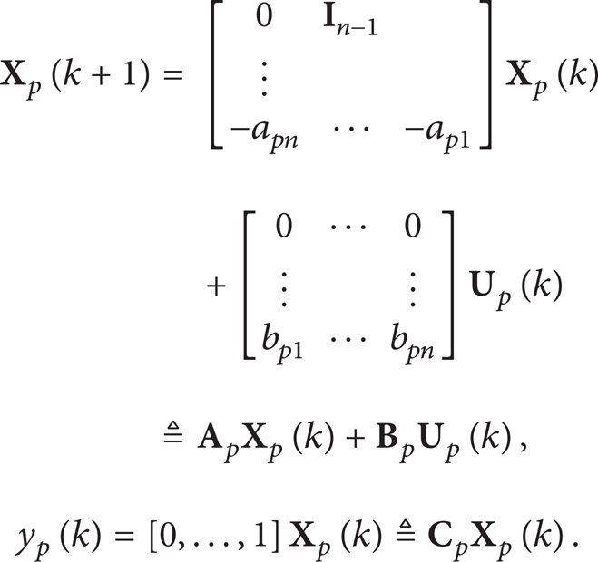
Set the transfer function of the reference model, and the controlled object are
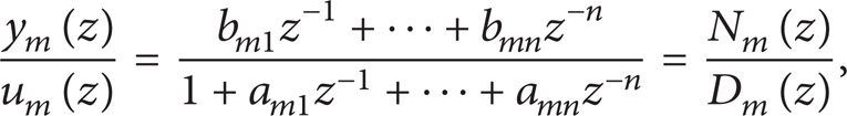

where the subscript m and p present the reference model and the controlled object, respectively, similarly hereinafter.
Then, the reference models of (4) are
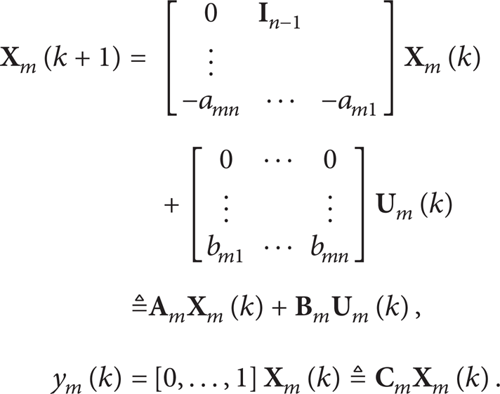
Similarly, the reference models of (5) are
Thus, the reference model and the controlled object both have the basic feather of controllable form and observable form.
Set state error as follows:

With (6) and (7), there will be

Set

where

4.2.2. PMF Conditions
To satisfy limx → ∞e(k + s) = 0, for all

So, the PMF conditions are
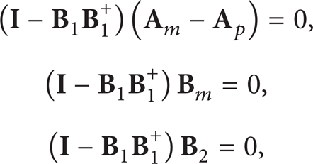
where
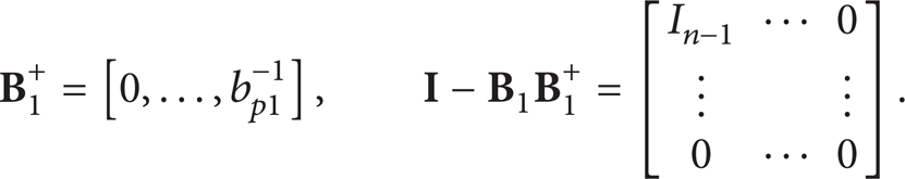
Through (6) and (7), only last rows in the matrixes (
4.2.3. Adaptive Law
So far, the state errors are
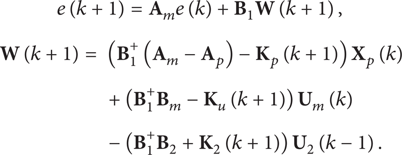
The physical meaning of

So,
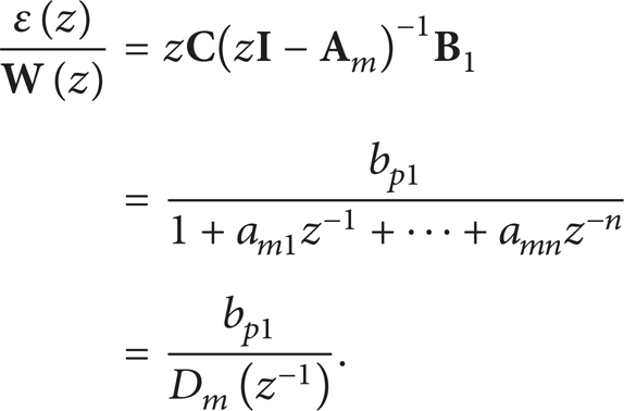
Design the compensator D, and select D(z) = d0 + d1z−1 + … + d l z−l to make the forward path
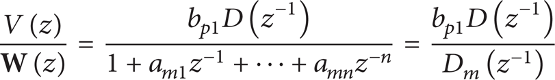
the strict positive real function, where V(z) = bp1D(z−1) is the output of compensator.
The typical equivalent feedback system applied in hyperstability theory meets the following Popov inequality:

It can prove that the gain matrix could be divided into the proportional and integral parts, respectively, to meet Popov inequality:
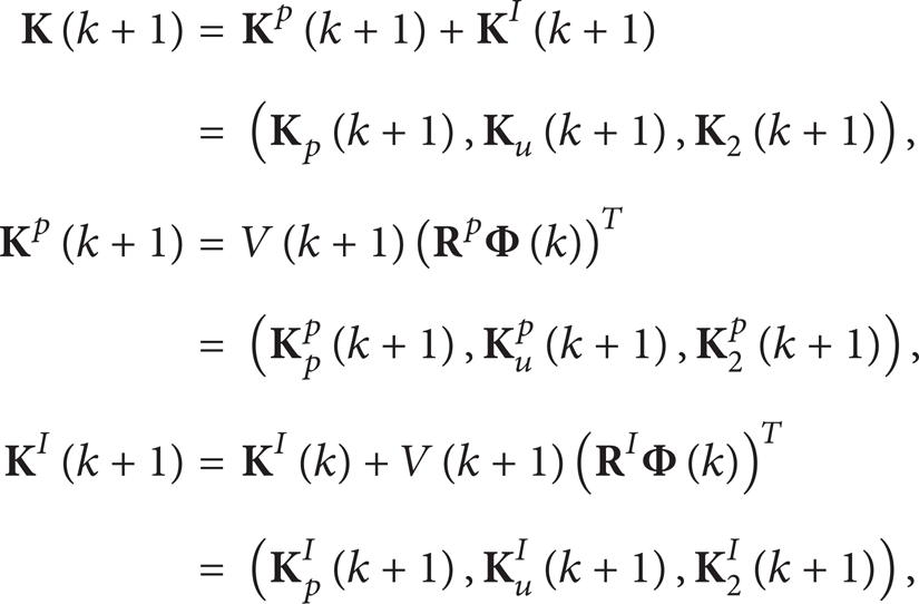
where superscripts p and I represent the proportional and integral part,
To calculate

Equations (10) and (20) present the algorithm implementation of the improved AMFC. The direct state method diagram is shown in Figure 6 [14, 15].

Structure diagram of direct state method.
5. Simulating Based on Improved AMFC
Build the improved AMFC system model in Simulink as Figure 7.

AMFC control block diagram of the excitation system.
The system response curves are shown in Figure 8 when the input is sinusoidal, triangular signal of the amplitude is 1 V, and the frequencies are 10 Hz, 20 Hz, 30 Hz, and 40 Hz, respectively. Because the adaptive control needs a period of time for adjustment, the amplitude will be of a certain attenuation in the process of the gain matrices

System responses in different frequencies (a) in sinusoidal signals and (b) in triangular signals.
It is clear that with AMFC controller, the system is of good following accuracy when the signal changes relatively gently, such as sinusoidal and triangular signals. However, when the mutation signals applied to the system, like square and sawtooth signals, the system adaptability becomes weak, as shown in Figure 9.

System responses in different frequencies (a) in square signal and (b) in sawtooth signal.
But according to the trend, when the parameters change, the system with AMFC still follows well. Since the current system is designed with the minimum load stiffness and the system damping is slight, the system responses would be much stable when the damping or the load stiffness increases [16]. The response curves are presented in Figure 10. When load stiffness K b in Table 2 increases to 320 MPa/m, the amplitude is 1 V, the frequencies of sinusoidal signals are, respectively, 10 Hz, 20 Hz, 30 Hz, and 40 Hz, and that of square signals and sawtooth signals are 10 Hz and 30 Hz.

System responses when load stiffness increases in different frequencies (a) in sinusoidal signals, (b) in triangular signals, (c) in square signals, and (d) in sawtooth signals.
6. Conclusion
The dynamic response of the uncorrected system of the high-speed railway in situ testing system is very slow and lags much, so it can hardly be used directly.
The improved AMFC algorithm based on the direct state method does not need online identification and much priori knowledge and can automatically satisfy with PMF conditions, which is very suitable for engineering practice.
Controlled by the improved AMFC algorithm, the following performance of the hydraulic servo excitation system improved a lot, and the system is insensitive with interruption that can meet the requirements basically.
The following performance becomes better when load stiffness increases.
Footnotes
Acknowledgment
The authors would like to offer their gratitude to the National Natural Science Foundation of China for their financial support. The Grant nos. 51027002, 51175386, and 51175388.