
Abstract
The inspection of pipe inside is very important so as to ensure the safety of pipe transmission. The pipe defect detection method based on inside 3D points acquired by circle structured light vision system was discussed in this paper. Based on the characteristics of 3D points inside a pipe acquired by circle structured light, a method by which pipe inner surface convex defect and pit defect were identified by the normal vector angle between adjacent points change on the same circle was proposed. A distance constraint between each pair of corresponding adjacent two points was proposed in order to recognize holes in the pipe inside. Based on Delaunay triangulation principle, the triangulation method for pipe inner surface circle structured light vision 3D points with hole and without hole was discussed and 3D reconstruction of the pipe was then realized. On the VC++ 6.0 software platform, pipe inner surface defect simulation data, hole simulation data and real 3D data were used to test the correctness of pipe defect identification method.
1. Introduction
Pipe transmission is the most important mode for transmitting liquids and gases. Many aging pipes are suffering from corrosion caused by high causticity of the liquid or gas transmitted. Therefore the inspection of pipe inside is very important to ensure the safety of pipe transmission and avoid leakage.
The traditional pipe inspection technology includes ultrasonic technology [1] and magnetic flux leakage (MFL) technology [2], which make it necessary that the pipe be scanned along the concerned area because only a limited area of the pipe is measured each time by these methods and the detection efficiency of these techniques is very low. Video technology is used to inspect the pipe inside since quantity information can be obtained by cameras and information is visualized [3]. The video inspection system consists of a high-resolution video camera and a lighting system, with the camera connected via a multicore cable to a remote computer and the pipe corrosion status can be determined by acquired images. Duran et al. [4] tried to inspect the defect of the pipe inside with a laser-based transducer. But the accuracy was low and the method could not exactly determine the pipe corrosive rate so the service period could not be estimated precisely. Machine vision technology is used to measure the 3D shape of the object and the accurate space dimension of the piece. It is expected that the pipe inside defect can be spotted by machine vision system accurately so that the pipe corrosive rate can be determined by the result of 3D measurement. And the pipe service period can be thus estimated accurately.
The visualization of the pipe inside defect can be conveniently utilized to determine the pipe corrosive status. So the reconstruction of the pipe inside and identification of the defect based on the 3D points are very important. The problem of surface reconstruction based on scattered points has been studied extensively and many surface reconstruction algorithms have been proposed [5, 6]. These algorithms can be generally classified into three types: computational geometry, algebraic and implicit methods. Computational geometry methods use mechanisms such as Delaunay triangulation and region growing. Algebraic methods reconstruct a surface by fitting a smooth function to the set of input points. Such methods cannot be used to reconstruct complex geometry or surfaces with boundaries. The most popular approach to surface reconstruction is based on the use of implicit functions [7, 8]. But implicit function methods also cannot be used to directly reconstruct surfaces with boundaries. When the surface contains boundaries, all methods mentioned above tend to produce incorrect results.
The main defects in the pipe inside are protrude, depression, or holes eroded by the medium transmitted in the pipe. The accurate position and the boundary must be detected before reconstruction. So a new triangulate method built upon the regular 3D points is proposed and the problem of boundary detection is solved.
The rest of the paper is organized as follows: Section 2 describes the principle of the circle structured light vision system and discusses the defect detection methods of pipe inside; Section 3 provides a detailed description of the method of 3D reconstruction; the results of defect detection and reconstruction based on real and simulative 3D dataset are given in Section 4; the conclusion is summarized in Section 5.
2. Defect Detection Method Based on 3D Points Acquired by Circle Structured Light Vision
2.1. Principles of Circle Structured Light Vision System
It is feasible to obtain the 3D points by the structured light vision technology. Since the section of the pipe inside is usually circle, the circle structured light is used to inspect the pipe inside. The circle structured light vision system for pipe inside detection consists of the CCD camera A, the laser B, and the pipe inspected, which is shown in Figure 1. The light emitting from the laser B is modulated into the conic surface light by the cylindrical grating, and the conic surface light projecting onto the pipe inside intersects with the inner wall and forms a closed stripe. So it is obvious that a triangle is constituted by the CCD camera A, the laser B, and the arbitrary point C on the stripe, and the 3D information of the point C can be obtained by the optical triangle [9]. If there are protrusion and depression in the pipe inside, the shape of the stripe could be changed as shown in Figure 2, where the stripe is curved near to the circle center when the protrusion is detected in the inner side. The stripe is circular when no defect is detected in the pipe inside. The pipe can be moved along its axis within a fixed small interval and the 3D information of different sections along the axis can be obtained. The images of the stripe of the pipe inside gathered by the CCD camera are transmitted to the computer via the cable. So the 3D points on the same section of the axis obtained by the circle structured light vision form a circle, and all 3D points obtained by the circle structured light vision form different circles corresponding to different sections of the axis. The structured light vision measuring system for pipe inside is shown in Figure 3. The circle structured light emitting from the laser projected onto the pipe inner wall and formed a closed stripe, and this stripe was gathered by the CCD camera. The pipe was moved along its axis within a fixed small interval and the other stripe on the pipe inner wall at a different position was obtained and gathered. After the system was calibrated, the 3D information on different stripes was obtained by the optical triangle. The pipe diameter size was measured due to the size of the laser and the CCD camera because the system should be put into the inside of the pipe.

The principle of circle structured light vision.

curved stripe of pipe inside with defection.

Circular structured light inspection system.
2.2. The Detection Method of Protrusion and Depression Defects
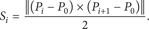
Normally the 3D points of the pipe obtained by circle structured light vision system form many circles corresponding to different sections of the axis. When 3D points on the circle distribute equably, the tangent vector change of the neighbor points is continuous. This can be illustrated in Figure 4, where the points P i , Pi + 1 are neighbor points on the same circle, their tangent vectors are t i , ti + 1, respectively, and their corresponding normal vectors are n i and ni + 1. The angle θ describes the normal vector change of the neighbor points, where θ equals the tangent vectors change of the points P i , Pi + 1 because the tangent vectors are perpendicular to the normal vectors, respectively. It can be seen that the angle θ is very small when the pipe inside is smooth. But when there is a defect in the interior, the tangent vectors of the neighbor points change sharply at the start position of the defect, as shown in Figure 5, where P i and Pi + 1, P j and Pj + 1 are the neighbor points on the same circle and points Pi + 1 and P j are the start positions of the defection. The angle θ i between the normal vectors of n i and ni + 1 and the angle θ j between the normal vectors of n j and nj + 1 equal the angle of their tangent vectors, respectively. It can be seen that the tangent vectors of the neighbor points change sharply in the defect position, as the angle θ i and the angle θ j are larger than angle θ where no defection is detected. So it can be concluded that if the angle between the normal vectors of adjacent points is larger than the threshold θ t , we can determine that the defect must exist in this area. Otherwise, no defection exists in the area. The threshold angle θ t is determined by formula (1), where n is the number of the points on the same circle as follows:


The normal vector and tangent vector of points on a full circle.

The normal vector and tangent vector of points on a defective circumference.
In general, the angle between the normal vectors of the adjacent points on the same circle can be calculated by formula (2) based on the space geometry theory.

So the defection can be recognized by comparing the normal vector angle θ of the neighbor points at the start position of the defect to the threshold θ t . If the angle θ is larger than θ t , the defect must exist. Let d denote the distance between the point lying on the defect area and the center of the circle, and let r denote the inside radius of the pipe. The distance d can be calculated by formula (3), where the 3D coordinate of the defective point is (xi + 1, yi + 1, zi + 1) and that of the center of the circle is (x0, y0, z0) as follows:

If d – r > d t , where d t is the threshold distance, then the pipe inner side has a protrusion. Otherwise, if d – r < d t , the pipe inner side is cupped.
The point P0 on the circle is not an isolated point because there are many points around the point P0. Therefore, the normal vector of the point P0 is related to the normal vector of the triangle plane including point P0. Let us assume that there are m points near the point P0 as shown in Figure 6, and these points can determine m different triangle planes together with the point P0. The unit normal vector n i of the triangle plane determined by P0 and its neighbor point P i and Pi + 1 can be calculated by the following formula:


The vertex normal vector and triangle normal vector.
Accordingly the area S i of the triangle plane can be calculated by
Then the normal vector n0 of the center point P0 can be calculated by formula (6) where the weight value of the normal vector of each triangular plane is the area of each plane:

2.3. The Detection Method of Holes on the Pipe
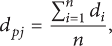
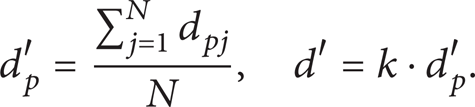
A hole is one of the main defects caused by erosion after the pipe has worked for a long time. The characteristics of 3D points measured by structured light vision technology with a hole on the pipe are different from those measured when no hole exists. Generally the 3D points of the pipe inner side measured by the structured light vision technology form different circles corresponding to different sections of the axis. To explain characteristics of the distribution of 3D points, each circle is rolled out as a line, as shown in Figure 7, where L1~L9 denote different pipe inner side circles measured by structured light vision system along the axis, respectively. When no hole exists, the distance between the neighbor points located on the same circle is short, while the distance between the neighbor points is long if there is a hole in this area. So the hole can be detected by comparing the distance between the neighbor points to the value d p ′. It can be seen that the distances of neighbor points on the circles L3 to L7 are denoted by B1B2, C1C2, D1D2, E1E2, F1F2, and all these distances are larger than d p ′. Thus, there must be a hole in this area. The distance of neighbor points on the circle L1 and L2 is shorter than d p ′, so there is no hole in this area. The value d p ′ is related to the point density of the circle. If the distance between the point P i and the point next is denoted by d i , the average distance d pj of all neighbor points on the same circle can be calculated by formula (7), where n denotes the number of the points in the circle, and the average distance of all neighbor points in all circles can be calculated by formula (8), where N denotes the number of circles along the p axis, and k is the coefficient which equals 1 normally:

Holes identification schematic of circle structured light.
3. The Three-Dimensional Reconstruction of the Pipe with a Hole
The aim of reconstruction is to restore the real shape of the object based on space points obtained by 3D measurement technology, which makes the object display visually. The triangulation of the space points is the key step of reconstruction on which the topology relationship of the neighbor points can be expressed by triangle meshes and the initial shape of the object can be restored precisely by these triangle meshes. The 3D points obtained by the circle structured light vision form different circles which distribute regularly, compared to the scattered points, and the triangulation of the regular points is simpler than that of the scattered points. So a new triangulation method based on the 3D points distributed on the different circles is proposed. This triangulation principle is explained in Figure 8, where L1 and L2 denote expanded lines of the neighbor circles, and P11, P12, …, P1m and P21, P22, …, P2n denote the points on the circles L1 and L2, respectively, in which m and n are the numbers of the points on the circle L1 and L2. The points P11 and P12 on the L1 and the point P21 on the L2 compose the triangle patch S1(P11P12P21). Symmetrically, the points P21 and P22 on the L2 and the point P12 on the L1 compose the triangle patch S2(P12P21P22). This process is repeated continuously until all points on the L1 and L2 are traversed. It can be seen that this triangulation method is simpler than the triangulation method of scattered points mentioned previously. It is noticed that when a hole exists, the triangulation should not be done on this area so as to restore the real status of the object.

Retaining holes during triangulation.
If a hole exists, which is shown in Figure 8(a), the area ABCD is a hole triangulated into the triangles mesh ABD and DBC, according to the principle mentioned above. To reserve the real shape of the object, the triangulation must not be done on the hole. So the boundaries of the hole must be identified in advance. Overall, steps of the triangulation with a hole are described as follow.
L i denotes the expanded line of the space points circle, where subscript i denotes the circle serial number, and P1, P2, P x denote the three vertices of the small triangle patch in which P1 is the first point on the line L i andP2is the first point on the line Li + 1 next to the L i .
Calculate the distance d1 between the point P1 and the next point on the line L i and the distance d2 between the point P2 and the next point on the line Li + 1. If all the distances d1 and d2 are smaller than the threshold value d p ′, then the triangulation is done (the detailed step was described in (3) and (4)). Otherwise the triangulation is not done. After that, the point next to P1 is set to be P1, the point next to P2 is set to beP2, and then the step mentioned above is repeated.
The point next to the point P1 on the line L i is set to be P x , and the points P1, P2, P x form a triangle. After the triangulation is done, the pointP x is set to be point P1.
The point next to the point P2 on the line Li + 1 is set to be P x , and then the new point P1 on the line L i , the new point P x , and the point P2 on the line Li + 1 form a new triangle patch.
The steps (2), (3), and (4) are repeated until all points on the line L i and line Li + 1 are triangulated.
4. Results of the Defect Detection and Reconstruction
4.1. The Results of Defect Detection and Reconstruction with a Hole
The simulation was done to demonstrate the effectiveness of our approach. The work was fulfilled by VC++ software platform and OPGL tool package. Figure 9 shows the reconstruction stages with the hole defect on the pipe. The simulated pipe was composed by 15 circles and 1380 points on these 15 circles. The radius of the pipe was 5.0 centimeters, the average distance between the neighbor points on all the circles was 0.32 centimeters, and the d p ′ was set to be 0.66 centimeters. It is obvious that the hole was identified by the approach explained in Section 2.2. Figure 9(a) shows the identified hole and Figure 9(b) is a local zoom-in out of the triangle mesh near the hole. It can be seen that the hole was not triangulated and was reserved. Figure 8(c) is the result of reconstruction of the pipe in which illumination condition was considered.

Three-dimensional reconstruction of circular hole on the pipe surface.
Figure 10 shows the stages of reconstruction with an irregular hole on the pipe. The pipe is composed by 8 circles and 720 points on these 8 circles. The radius of the pipe was 5.0 centimeters, the average distance between the neighbor points on the all circles was 0.35 centimeters, and the d p ′ was set to be 0.58 centimeters. Figure 10(a) shows the identified hole and Figure 10(b) is a local zoom-in out of the triangle mesh near the hole. It can be seen that the hole was not triangulated. Figure 10(c) is the result of reconstruction of the pipe in which illumination condition was considered. It can be concluded that the hole detection method proposed in this paper is effective both for regular holes and irregular holes.

Three-dimensional reconstruction of irregular polygon hole on the pipe surface.
4.2. The Results of the Defect Detection and Reconstruction with a Protrusion
Both real and simulative data sets were used to demonstrate the effectiveness of our defection detection method. Figure 11 shows the stages of reconstruction with the protrude defection in the pipe inside. The pipe is composed by 14 circles and 952 points on these 14 circles. The radius of the pipe is 5.0 centimeters, the angle θ t is set to 5.5°, and the distance d t is set to 0.05 centimeters. Figure 11(a) is the space points of the pipe inside and Figure 11(b) is the triangulate mesh of the pipe, where the area marked with red color is the identified protrude defection. Figure 11(c) is the result of reconstruction of the pipe with defect in which illumination condition was considered.

Three-dimensional reconstruction of protrude defection of the pipe inside.
Figure 12 shows the stages of reconstruction of a real cupped defect in the pipe inside. The pipe is composed by 11 circles and 2123 points on the 11 circles obtained by the circle structured light vision. The radius of the pipe is 4.45 centimeters, the threshold value θ t of the adjacent points is set to 2.0°, and the distance d t is set to 0.25 centimeters. When the normal vector angle of the neighbor point is larger than 2.0° and the distance between the defect point and the center of the circle is smaller than 4.20 centimeters, the area which includes this point can be determined as a protrude defect. Figures 12(a) and 12(b) describe the space points and the result of triangulate mesh of the pipe, where the area marked with red color is the identified protrude defect. Figure 12(c) is the result of reconstruction of the pipe in which illumination condition was considered. It can be concluded that the defect detection method proposed in this paper is effective.

Three-dimensional reconstruction of cupped defection of the pipe inside.
5. Conclusion
In this paper, the pipe defect detection methods based on space points for both the holes and inside concavoconvex were proposed. The holes in the pipe can be identified by comparing the distance of neighbor points to the threshold value which can be determined by density of the points. The defects of protrusion and being cupped are detected by identifying where the normal vector angle of the neighbor point changes sharply. The new triangulation method based on the regular 3D points was proposed in this paper. The results showed that the reconstruction method for the regular points was simpler than that of the scattered points and the hole could be reserved. The defect detection and reconstruction result for the 3D points distributing regular is satisfied by the methods mentioned above, but the result for the 3D scattered points is not suitable for these methods. The defect detection and reconstruction methods were validated by a test built upon the VC++ and OPGL tool package.
Footnotes
Acknowledgment
This work has been supported by the National Natural Science Fund of China (Contract no. 50975019).