
Abstract
Great concern for the safety of high rock-fill dams which are being or to be built in the southwestern area of China with high seismicity is attracted. In order to obtain an in-depth knowledge of the mechanism of seismic-induced damage and reasonable assessment of the seismic design for rock-fill dams, comprehensive dynamic centrifuge tests which can simulate and reproduce strictly the action process of strong earthquake should be conducted. Thus, the performance and accuracy of test device have become a key problem. In the present research, refined calibration of bidirectional shaker table, which can be actuated in both horizontal and vertical directions simultaneously and placed on the swing bucket, was achieved via the distributed sensor network used in a centrifuge model test. The seismic input at the dam site and transmission along the dam axis were obtained by the five pairs of accelerometers. The extensive usage of the sensor networks technology in physical model test in centrifuge has significantly promoted the calibration of performance of bidirectional shaker table and would thus enable further insight into the dynamic response of rock-fill dam.
1. Introduction
Numerous high rock-fill dams with the height of more than 200 m are being or will be built in the southwestern area of China with high seismic risk. Hence, the issue of dam safety against strong earthquake shocks is of great concern [1, 2]. Moreover, during the 1994 Northridge earthquake, the 1995 Kobe earthquake, the 1999 Chi-Chi earthquake, and the 2008 Wenchuan earthquake, field observations on vertical ground motions showed different features from those of the horizontal motions. For example, the records at the reclaimed Port Island in Kobe showed that the ratio of peak vertical to peak horizontal acceleration was as large as 1.5 to 2. This value substantially exceeded 1/2 or 2/3, a value commonly used in engineering practice. On the other hand, the field observations also showed that vertical input motion was significantly magnified at the dam crest. Thus, vertical acceleration has been an issue of debate following recent major earthquakes, but its potential effects are yet to be investigated [3]. Additionally, given that the devastating damage induced by large earthquakes is infrequent and unrepeatable, it is difficult to obtain the required data to study their effects by postearthquake field investigations [4]. Meanwhile, instrumentation of high rock-fill dam is expensive to maintain over a long period of time that may elapse after major shocks, and the instrumentation may not be placed in the most scientifically available locations [5]. Thus, considering the aforementioned necessity and limitations, the centrifuge model test coupled with bidirectional shaker table is a valuable tool to study the effects of ground shaking on high rock-fill dams without risking the safety of the public [6, 7].
This approach has a potential value in the ongoing monitoring of dynamic response of rock-fill dams subjected to strong earthquakes. However, how to efficiently and accurately obtain the real-time data from dynamic centrifuge model test becomes a key problem [8–10]. Historically, sensor networks have usually been used to obtain real-time data and its duration in the physical events. This knowledge used to improve the performance of the process and its control brings about several benefits [11–13]. As we know, the automation and control systems for the real-time data via networks including the data acquisition system (DAQ) and the personal computer (PC) can be realized during the complex test processes. Nowadays, the most well-known models in the networks include Foundation Fieldbus, WorldFIP, ControlNet, and DeviceNet. They provide efficient networks for the maximization of data changes and increasing flexibility [14, 15]. Moreover, with the development of the computation software, the knowledge of microprocessors and microcontrollers leads to several intelligent instrumentations to enhance the efficiency and stability of networks. Thus, the mode of sensors adopted in the networks can play an important role in conducting the model test [16]. Cheekiralla [17] pointed out that the results which were obtained from the centrifuge model tests via the wireless sensor networks installed in the sealed and high-speed vessel were sometimes difficult to interpret or understand. Thus, considering the high rotating speed and leakproofness of dynamic centrifuge test coupled with bidirectional shaker table, a sensor network constructed by the optical-fiber sensors is suggested. The instrumentation communication can be obtained efficiently and accurately by the connections with optical-fiber cable between the sensor element and data acquisition system (DAQ) [18]. The progress is more significant when the access to the measurement networks takes place by optical-fiber technology, enabling a fast reading of the processes variables or the monitoring of the test conditions.
In the present study, the dynamic model test for a typical rock-fill dam in bidirectional shaker table coupled with a geotechnical centrifuge, which uses practical instrumentation technology and optical cables for data transfer, is carried out. The acquired experience with optical-fiber technology could be used to calibrate the accuracy and performance of the bidirectional shaker table placed on the large centrifuge installed in China Institute of Water Resource and Hydropower Research [19].
2. Dynamic Model Tests in Centrifuge
As we know, the dynamic properties of rock-fill materials exhibit a close correlation with the effective confining stress and stress history. The centrifuge can simulate and reproduce the identical self-weight stresses in the prototype by applying an increasing gravitational acceleration to the physical model. Through refined control of the effective confining stress, accurate data can be obtained, which facilitates accurate solution to complex problems such as earthquake-induced response, liquefaction, and permanent deformation. It is proved that dynamic model tests in centrifuge not only provide data to improve our understanding of mechanisms of dynamic-induced damage but also provide useful proof for verification of numerical models. Additionally, with the development of sensor network for the precise measurement of stress and strains, the quantity and quality of information obtained from dynamic centrifuge tests on models can be substantially increased as a result of the improvement of instrumentation and systems for processing data.
For in-depth research into geotechnical problems, the physical model test is regarded as an important tool for its convenience and practical applicability. Sophisticated characteristics of the prototype can be well represented by the model. In practice, the smaller the model is, the more difficulty is involved in the manufacture and instrumentation process. The accuracy of the test results can be affected by many other factors, such as properties of materials, model design, loading techniques, measurement methods, and recording of results. More importantly, the models must be designed and examined in accordance with the laws of similarity between them and the prototypes. The laws of similarity are based on the modelling theory and dimensional analysis of the physical phenomenon involved. Scale factors for independent parameters are chosen based on the uniform factor. Given that the phenomena observed in the models reflect those of the prototype, it is necessary to meet the similarity requirements. Geometric similarity is easy to be achieved, but full similarity concerning all physical quantities involved is difficult to attain so far. In such cases, it is necessary to justify the differences, checking their influences on parameters and on the results.
The choice of materials in a model test must consider stress limits, stiffness, rupture mechanisms, the influence of temperature and humidity, and loading speed as well as size and form. However, it is a benefit that, in the centrifuge model test, unit scale of stress can be achieved by using the same materials as in the prototype. The success of experimental program mainly depends on the precision and reliability of measurements. In order to reach the same precision for tests as in the prototype, uniform scale factor must be applied to instruments in model simulations. The accuracy of model tests can be improved with the use of statistical analyses in data interpretation and appropriate instrumentation. Model instrumentation includes identifying the quantities to be measured and selecting measurement sensors and their installation and calibration processes. Table 1 presents a list of the main physical parameters and scale factors between model and prototype involved in the dynamic centrifuge model.
Physical parameters and scale factors.

In general, the study of high rock-fill dam subjected to strong earthquake in actual scale is impractical. Thus, dynamic centrifuge test is an important tool to reveal the response of high rock-fill dams when subjected to real-time input motion, which can be reproduced by a small-scale model dam with near homogeneous condition in terms of dynamic parameters. Dynamic tests in centrifuge, especially those that deal with the effect of vertical accelerations on the geotechnical model, have never been developed so far for the difficulties and huge costs. In the study of rock-fill dam subjected to horizontal and vertical acceleration using reduced physical models in centrifuge, the stress level, dimensions, and geometry of model require special attention. Considering the seepage characteristic of rock-fill materials, the pore-pressure dissipation is not considered. Additionally, in order to reproduce the stress level and stress history existing in a rock-fill dam using a centrifuge, a special apparatus enabling the simulation of construction process and normal operation for the dam under increased gravity accelerations appears as an alternative. The centrifuge in IWHR (China Institute of Water Resource and Hydropower Research 2012), which has been established in combination of a bidirectional shaker table (with both horizontal and vertical actuators), has been used mainly for academic research purpose. It is certainly a promising tool for technological innovations in the geotechnical earthquake engineering.
3. Description of Bidirectional Shaker Table in Centrifuge
An R-500B bidirectional shaker table to use with a large geocentrifuge, which can further the research for dynamic response analysis of large geotechnical structures such as rock-fill dams, was established in IWHR in 2012, as shown in Figure 1. It is noted that the coupled horizontal and vertical actuators are adopted in the bidirectional shaker table. The R-500B shaker table consists of a swing basket for the centrifuge that is isolated from the centrifuge arm via 8 elastomeric pads on 8 high-strength 100 mm diameter steel studs. This isolation limits the dynamic forces transmitted from the table operation to the centrifuge arm.

Bidirectional shaker table in the centrifuge.
The bidirectional shaker table is located inside an outer frame included in the swing basket. The table is designed to move in both the horizontal and vertical directions simultaneously using laminated rubber bearings. The vertical table is an aluminum plate weldment. It is driven by the vertical actuator (Ac) reacting against the base of the outer steel frame. The horizontal table is a single aluminum plate supported by laminar bearings on top of the vertical table. It is driven by the horizontal actuator (At) acting against the outer steel frame. The horizontal actuator is connected to the horizontal table using a combined laminated and precompressed flexure bearing that allows the horizontal table to move in the desired biaxial manner. The test item is mounted on the top of the horizontal table. Figure 2 shows the operation of the bidirectional shaker table in the centrifuge room. The system has been designed for a safety factor of 2.5 when operating at a maximum acceleration of 80 g.

The operational system of bidirectional shaker table.
Besides, the highly configurable and powerful LabVIEW-National Instruments technology which consists of a data acquisition system and ANCO-Dance system is adopted in the centrifuge model test via the sensor network. Numerous data such as displacement, strain, stress, and acceleration can be obtained by the combined system, as shown in Figure 3.

The data acquisition system in IWHR centrifuge (ANCO-Dance user manual [20]).
4. Dynamic Centrifuge Model Tests with Sensor Networks
The centrifuge has been employed for experiments on rock-fill dams. In the current research, the performance of the bidirectional shaker table in centrifuge model tests is calibrated using sensor networks. It is a special and innovative dynamic test apparatus, which can be actuated in both the horizontal and vertical directions simultaneously. The calibrations of the apparatus were conducted for accelerations below 40 g. The test model and distribution of optic-fiber accelerometers are shown in Figure 4. Table 2 presents the calibration coefficient of accelerometers. The soil particle composition of rock-fill material used in the test is listed in Table 3.
The description of accelerometers.

The grading of rock-fill materials.


Model layout and instrumentation (unit: mm).
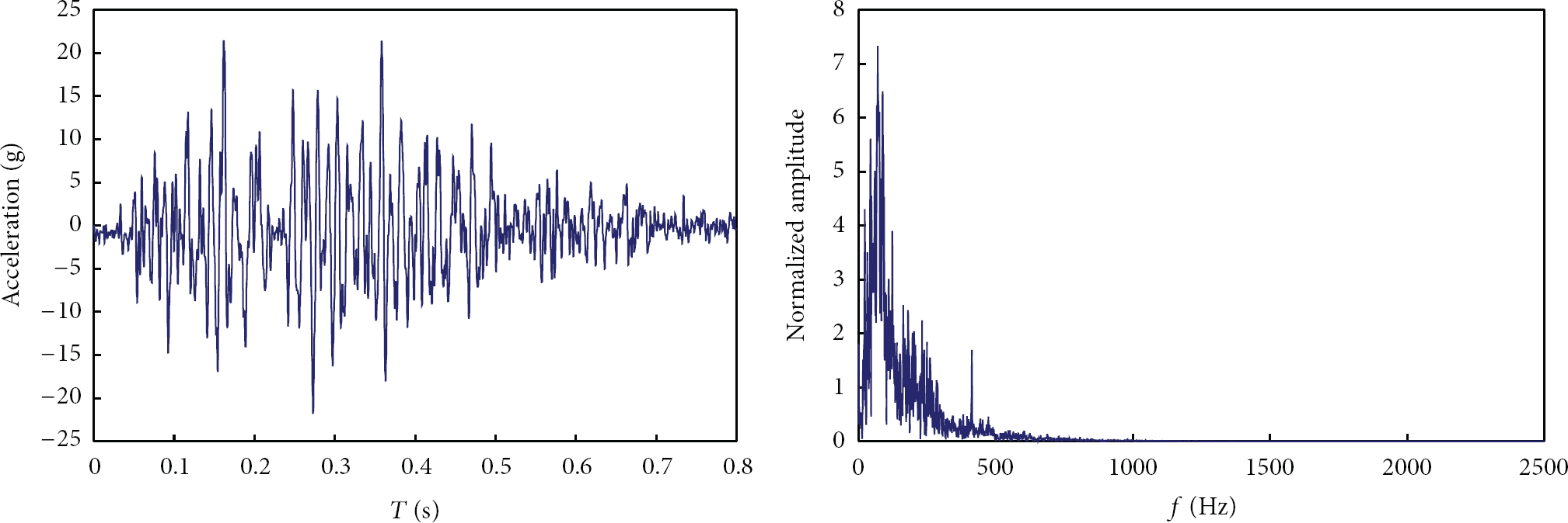
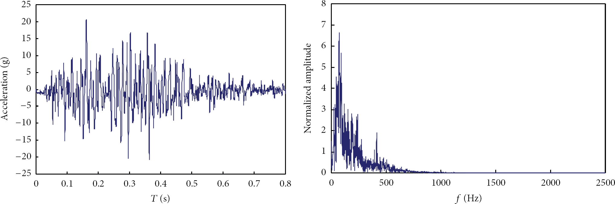
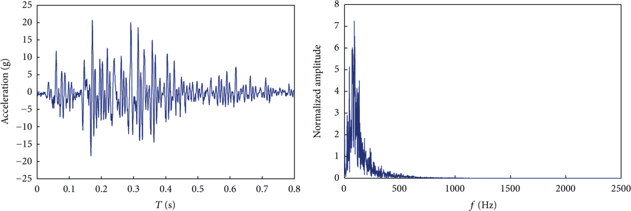
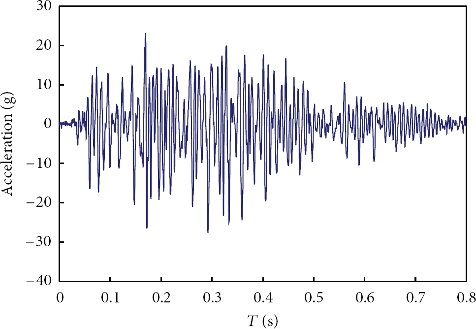
The soil used for the model of rock-fill dam was acquired from the Zipingpu concrete face rock-fill dam in Sichuan, China. The soil has a specific gravity of 2.19. Figure 5 shows the photo of the dam model on the bidirectional shaker table. The models were symmetric with an initial height of 268 mm. They were constructed by sequentially placing the five horizontal layers of soil on the table. The soil was compacted to reach the designated dry density. Five pairs of miniature accelerometers were buried in the model to monitor and record the dynamic response in the dam (Figure 4), and the optic-fiber sensors were numbered as ACC0 (located on the shaker table), ACC1, ACC2, ACC3, and ACC4, respectively. Each pair of sensors can measure the horizontal and vertical dynamic responses of the dam simultaneously. After the installation of the model on the centrifuge machine, the speed of the centrifuge was slowly increased to reach a desirable centripetal acceleration of about 40 g in 15 min. At this moment, an acceleration time history recorded in a real earthquake scaled to the amplitude of 20 g (corresponding to 0.5 g for the prototype) was triggered. The duration of the input motion is 0.8 second and the time increment is 0.0002 second. The time history of input motion and Fourier amplitude spectrum are shown in Figure 6. In this study, the same input motion is used in the horizontal and vertical directions. Considering the high permeability of rock-fill materials, the accumulation and dissipation of excess pore pressure were neglected. For in-depth comparison, two model tests which were actuated in two different modes were performed for this rock-fill dam to reveal the performance of the bidirectional shaker table in centrifuge, as listed in Table 4. Additionally, one refined software application, which is formulated based on LabVIEW package, was developed to record the test data.
Cases of dynamic model test.
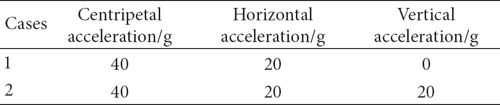

Photo of preearthquake test model.

Input motion and Fourier amplitude spectrum.
4.1. Model Dam Subjected to Unidirectional Earthquake (Case 1)
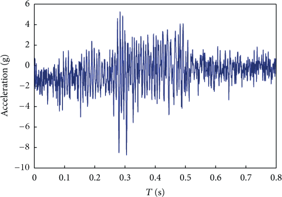
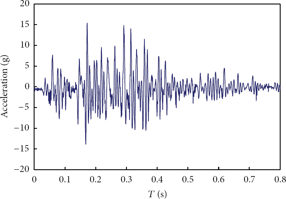
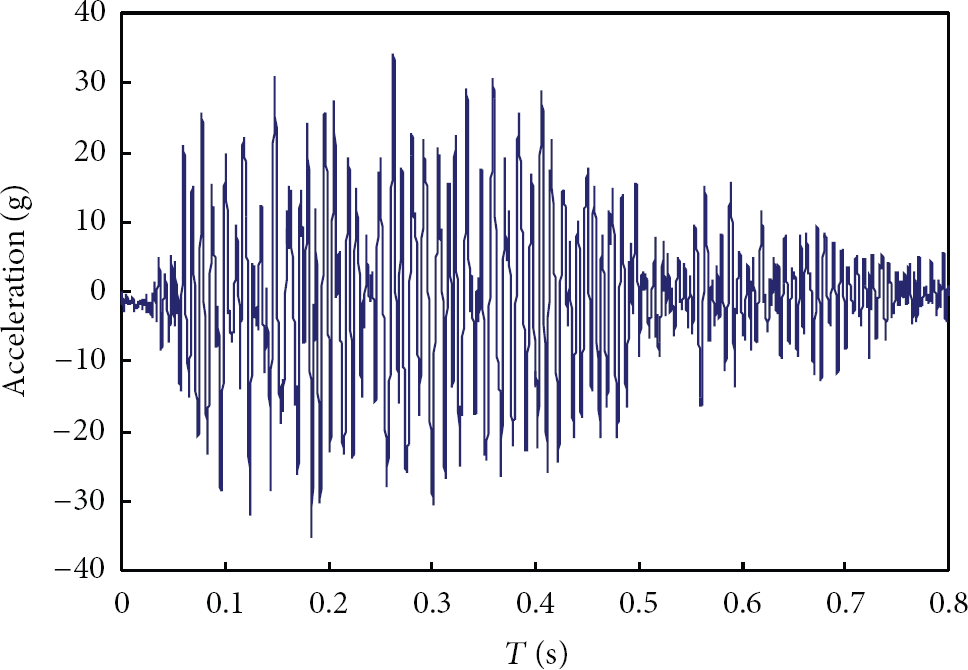
Figures 7, 8, 9, 10, and 11 show the time histories of the response acceleration (model scale) and their Fourier amplitude spectra during the simulated earthquake along the height of the rock-fill dam. The maximum input seismic acceleration on the bottom of the container was 20 g, with some high-frequency contents as illustrated by its corresponding Fourier amplitude spectrum. Good consistency of amplitude and Fourier spectrum between the input motion and the record on the accelerometer ACC0-H located on the shaker table can be obtained, with only minor difference observed. Besides that, the accelerometer ACC4-H in the upper portion, located at 43 mm below the top of the embankment, recorded a peak acceleration of 35 g. The amplification factor on the dam crest in the horizontal direction is about 1.6 times. From the recordings by the accelerometers ACC2-H and ACC3-H, it is noted that the corresponding amplitude of response acceleration decreased at the middle of the dam. This phenomenon has also been found from the in situ field monitoring and the results from the numerical analysis of rock-fill dams.
Time history of horizontal acceleration recorded by ACC0 and Fourier amplitude spectrum.

Time history of horizontal response acceleration recorded by ACC1.
Time history of horizontal response acceleration recorded by ACC2.

Time history of horizontal response acceleration recorded by ACC3.
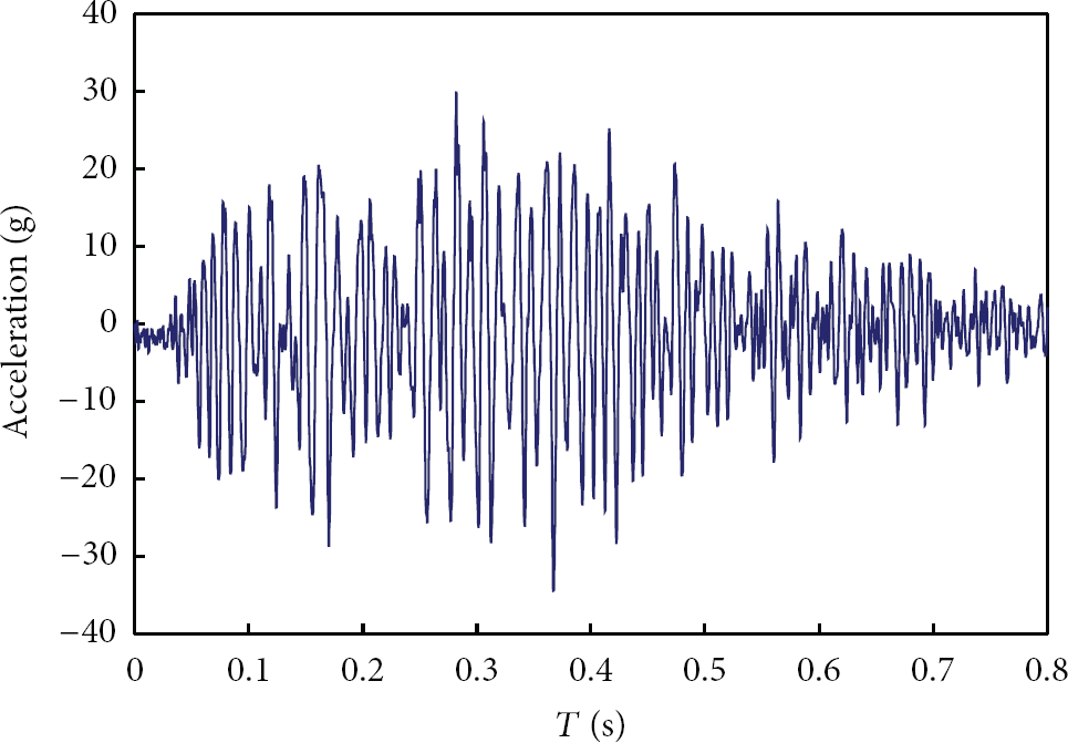
Time history of horizontal response acceleration recorded by ACC4.
4.2. Model Dam Subjected to Bidirectional Earthquake (Case 2)
Figures 12, 13, 14, 15, 16, and 17 provide the time histories of response acceleration in the horizontal and vertical directions as well as the corresponding Fourier spectra. The response acceleration was measured by the distributed accelerometers along the dam axis. The measured maximum input acceleration from the pairs of accelerometer ACC0 was 20.5 g in the horizontal direction and 20.7 g in the vertical direction, which is very close to the design that the model be shaken in the horizontal and vertical directions with the same magnitude of acceleration (20 g). From the recordings by the accelerometers along the dam axis, the peak acceleration in the horizontal direction decreased by 20% at ACC1-H but increased 45% at ACC4-H, lower than that measured in the case 1 test. The similar trend of variations in the acceleration was also found in the vertical direction. Figure 18 shows the distribution of amplitude of measured accelerations in the middle section with the height of the model dam. It is shown that the maximum amplitude of acceleration in the horizontal direction and the corresponding acceleration in the vertical direction tended to decrease slightly in the middle of the dam but increased more rapidly in the upper portion, during the bidirectional shaking (refer to Figure 18). This may result in a higher peak acceleration observed near the dam crest.
Time history of horizontal acceleration recorded by ACC0 and Fourier amplitude spectrum.
Time history of vertical acceleration recorded by ACC0 and Fourier amplitude spectrum.

Time history of horizontal acceleration recorded by ACC1.
Time history of vertical acceleration recorded by ACC1.
Time history of horizontal acceleration recorded by ACC4.
Time history of vertical acceleration recorded by ACC4.
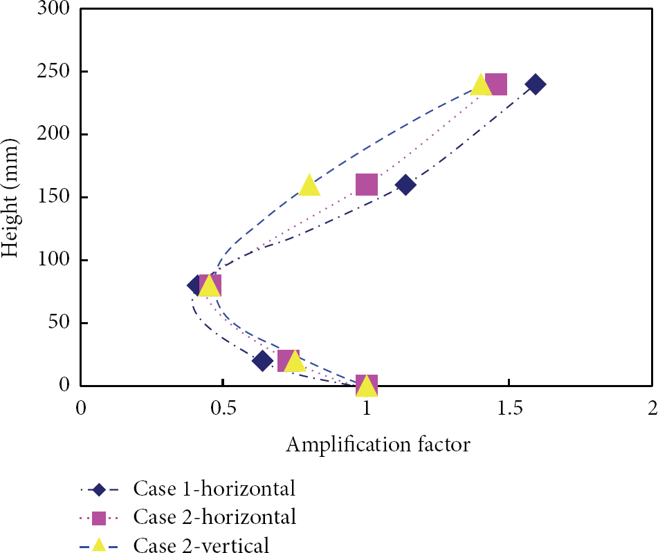
Amplitude of response acceleration along the dam height.
5. Conclusion
In summary, two typical centrifuge model tests coupled with the distributed sensor network on a rock-fill dam were carried out to investigate its dynamic response when subjected to uniaxial and biaxial shaking. Good agreement between input motion and the record of shaker table has been observed based on the optimized sensor network. Besides, the distribution of response acceleration along the dam axis is consistent with that obtained from in situ tests and numerical analysis. The sensor network adopted in the dynamic centrifuge model test can provide reliable data to track the dynamic response of rock-fill dam when subjected to an earthquake excited in both the horizontal and vertical directions. It is concluded that the performance of the bidirectional shaker table in centrifuge can be guaranteed based on the test results recorded by the sensor network. The bidirectional shaker table in conjunction with the large centrifuge is proved to be an effective and powerful tool for the design and analysis of high rock-fill dams with high seismic risk.
Footnotes
Acknowledgments
The financial support by the National Nature Science Foundation of China (51009021), Special Scientific Research Foundation of China Institute of Water Resources and Hydropower Research (Yanji1307), and the National Key Basic Research Program of China (no. 2013CB036404) and experimental data and technological support from the Centrifuge Laboratory are gratefully acknowledged.