Analysis of heat transfer through different candidates for high performance fins is considered in this work. These candidates are: (A) fins of constant cross-sectional area, (B) fins of constant cross-sectional area gradient, and (C) radial fins with power-law cross-sectional area distribution. The types (A) and (B) fins are allowed having variable power-law profile distributions. The energy equation for each case is solved analytically, and closed form equations for various performance indicators including the fin efficiency are obtained. It is identified that high performance fins are those fins having larger tip and surface areas and smaller tip thickness than those of the straight fin. These effects tend to augment the fin heat transfer rate. One of the indicators of the type (A) fins is found to become dependent on the tip thickness when it is smaller than the base thickness and for thermal lengths larger than 1.5. The type (C) fins are found to transfer more thermal energy than the type (B) fins under same tip area and tip thickness. Finally, generalized correlations for the fin efficiency of high performance fins as function of base and tip areas and thicknesses and the thermal length are proposed and validated.
1. Introduction
Fins are extensively used in different industrial systems [1–9], especially in heat exchangers, cooling devices of internal combustion engines, and energy management components of electrical appliances. The extra surfaces provided by the fins are used to augment the heat transfer between the solid surface and the adjacent fluid stream [6]. Various mathematical analyses of conduction heat transfer inside fins have been extensively performed in the literature [5, 9]. These analyses were launched with the work of Harper and Brown [7] who found that one-dimensional analysis is sufficient for heat transfer inside fins. Furthermore, they recommended consideration of corrected fin length, equals to half of the fin thickness added to its length, so as to account for the tip heat loss.
Among the pivotal works in heat transfer analysis inside fins is the work of Murray [8]. He proposed a set of assumptions that have been utilized universally in the analysis of extended surfaces. These assumptions have been known as Murray-Gardner assumptions [9]. Another fundamental work in this domain is the work of Gardner [10]. In this work, Gardner [10] reemphasized the concept of fin efficiency. This concept has been exploited later on by thousands of works. Furthermore, he was one of the leading researchers who utilized the applied mathematics including the use of modified Bessel functions in solving the fin equation. An important literature review about mathematical analyses of fin equation is found in the work of Kern and Kraus [5] and Kraus et al. [9].
The heat transfer area of a typical finned surface is usually much larger than that for the plain surface area. However, most of the fin surfaces exchange thermal energy with the surrounding fluid at temperature difference smaller than that of the plain surface. Because of this fact, the fin efficiency expression or chart must be known before determining the heat transfer capability of the finned surface. Without this expression, accurate designs for the various thermal systems in industry cannot be achieved [11]. For that reason, many expressions or charts for the fin efficiency of different fin geometries can be found in the literature. For example, Kraus et. al. [9] included in their book many equations or charts for the fin efficiency of straight, spine, and radial fins of rectangular, triangular, and hyperbolic profiles. The objective of the present work is to find out a generalized correlation that can be used to estimate the fin efficiency of any kind of high performance fins. This task is vital in order to avoid seeking for the exact fin efficiency equation among the large number of researches devoted to this topic in the literature [12–19]. To achieve the latter objective, the common characteristics that most high performance fins share need to be identified and analyzed. It should be mentioned that the previous objectives received almost no attention in the heat transfer literature [18, 19]. As such, they have been considered as the main motivation behind the present work.
In this work, heat transfer through different candidates for high performance fins is mathematically analyzed. Three different types of fins are considered. They are: (A) fins of constant cross-sectional area, (B) fins of constant cross-sectional area gradient, and (C) radial fins with power-law cross-sectional area distribution. The fins of types (A) and (B) are considered to have a variable power-law profile distribution. The excess temperature for each fin type is obtained by analytically solving the appropriate form of the fin equation. As such, different fin performance indicators including the fin efficiency are computed. Based on the results of this work, the important characteristics of the high performance fins are identified. This is based on the fact that high performance fins transfer more thermal energy than the straight fin. Finally, generalized correlations for the fin efficiency of high performance fins are recommended.
2. Problem Formulation
In this work, Murray [8] assumptions are adopted. In addition, the square of the fin thickness gradient is neglected. That is, slender fins are only considered in this work.
2.1. Case A: Fins of Constant Cross-Sectional Area
In all of the cases studied in this subsection, the fin cross-sectional area A is considered to be constant over the whole length of the fin. Now, consider a rectangular fin having a thickness H(x) and width W(x) that are much smaller than its length L as shown in Figure 1. H(x) is considered to vary along the fin centerline axis (x-axis) according to the following power-law relationship:
where and p is the power-law index. Hb and HL are the fin thicknesses at the base (x = 0) and the tip (x = L), respectively. The dimensionless variable is given by . As the fin cross-sectional area is constant, the fin dimensionless width must be equal to
The fin dimensionless profile area and the dimensionless surface area exposed to convection are given by:
The application of the energy equation [20] to a fin differential element of length dx results in the following fin equation:
where . The quantities T, Tb, and T∞ are the fin temperature, fin base temperature, and the free stream temperature, respectively. The fin index m is given by , where h and k are the convection heat transfer coefficients between the fin and the surrounding fluid stream and the fin thermal conductivity, respectively. Equation (4) can be transformed to the following:
The adiabatic tip condition is considered. It is because the tip heat loss can be estimated using the corrected fin length concept proposed by Harper and Brawn [7]. Mathematically, the boundary conditions are given by
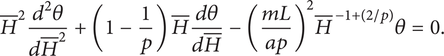
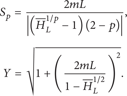
Equation (5) can be solved using the modified Bessel functions [21]. The solution of this equation when 0 ≤ p < 2, p = 2, and p > 2 is as follows:
where Sp and Y are given by
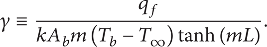
The fin heat transfer rate (qf) can be calculated from , where Ab is the fin cross-sectional area at the base. Define the first performance factor (γ) as the ratio of qf to fin heat transfer rate when . Mathematically, γ can be shown to be equal to
Thus, γ-expressions for the positive spectrum of p are equal to the following:
Schematic diagram for the candidate for high performance rectangular fin with variable width and thickness and the system coordinates, for radial fin W(x) = 2π(rb + x) and r = rb + x.
2.2. Case B: Fins of Constant Cross-Sectional Area Gradient
In all of the cases studied in this subsection, the fin cross-sectional area A is considered to vary linearly along fin length. As such, the dimensionless cross-sectional area function is equal to
As such, W(x) is related to H(x) through the following equation:
The application of the energy equation [20] to a fin differential element of length dx results in the following fin equation:
Equation (13) can be transformed to the following form:
Now, consider the following family of fin dimensionless thickness distribution:
where n is a real number. For these distributions, the fin dimensionless profile area and dimensionless surface area exposed to convection are given by
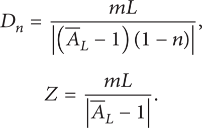
Equation (14) can be solved using modified Bessel functions [21]. The solution to this equation subject to boundary conditions given by (6) is equal to
where Dn and Z are given by
As such, the first performance factor for this family of fins (γn) is given by
2.3. Case C: Radial Fins with Power-Law Varying Cross-Sectional Areas
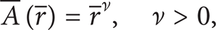
Let vary with the radial direction r according to the following power-law form
where and rb is the fin radius at the base. For radial fins of circumferential perimeter (W = 2πr), the fin dimensionless thickness must satisfy the following relationship:
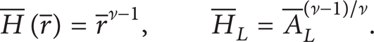
For this case, the fin dimensionless profile area and dimensionless surface area exposed to convection are given by:
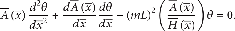
The one-dimensional heat diffusion equation [20] of the fin can be reduced to the following form:
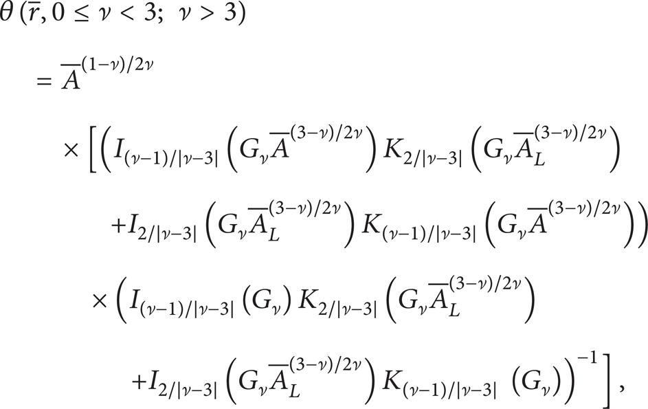
When 0 ≤ ν < 3 and ν > 3, the solution of (25) subject to boundary conditions given by (6) has the following forms [21]:
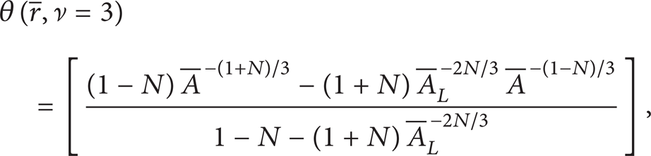
while it is the following when ν = 3:
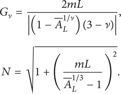
where Gν and N are given by
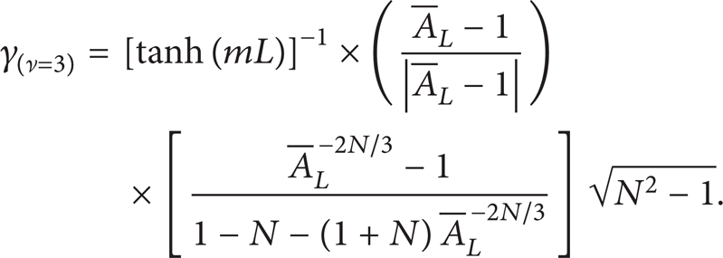
As such, the γ-indicators when 0 ≤ ν < 3, ν = 3, and ν > 3 are equal to
2.4. The Fin Efficiency Expression for the Different Studied Cases
The fin efficiency (ηf) is defined as the ratio of the fin heat transfer rate to the maximum fin heat transfer rate [20] which is obtained when k → ∞. It is related to the first performance indicator γ through the following relationship:
3. Results and Useful Correlations
The results of (10), (20), and (29) are presented graphically in terms of the various pertinent parameters in Figures 2–8. Furthermore, the following accurate correlations for and are obtained by trial and errors with the aid of advanced regression softwares:
The maximum percentage (relative) errors associated with correlations (31) and (32) are 2.3% and 1% when . These percentages become smaller than 3.9% when .
Effects of the dimensionless profile area , thermal length (mL), and dimensionless tip thickness on the first performance indicator for fins of case (A) when .
Effects of the dimensionless profile area , thermal length (mL), and dimensionless tip thickness on the first performance indicator for fins of case (A) when .
Effects of the dimensionless tip thickness and thermal length (mL) on the first performance indicator for fins of case (B) when .
Effects of the dimensionless tip thickness and thermal length (mL) on the first performance indicator for fins of case (B) when .
Effects of the dimensionless tip thickness and thermal length (mL) on the first performance indicator for fins of case (C) when .
Effects of the dimensionless tip thickness and thermal length (mL) on the first performance indicator for fins of case (C) when .
Comparisons between the first performance indicators of cases (B) and (C) under various values of thermal length (mL), dimensionless tip thickness , and dimensionless tip cross-sectional area .
4. Discussion of the Results and Recommendations
4.1. Discussion of the Results
For all cases, Ap increases as HL increases, thus Af decreases causing the heat transfer rate to decrease. Therefore, , and decrease as increases as shown in Figures 2, 4, 5, 6, and 7. Moreover, the increase in AL at a given HL is expected to cause an increase in Af for cases (B) and (C). This is clearly seen in (17) and (24). As such, both conduction and convection heat transfer rates increase as AL increases at given HL. Consequently, both and increase as increases at given . These trends can be seen from Figures 4–7. In addition, the fin effective thermal length for case (A) is expected to decrease as HL decreases. This is because Af increases as HL decreases. On the other hand, that effective length for case (A) is expected to be larger than that for the flat fin when HL > Hb. As a consequence, decreases as the mL increases when , and it increases as mL increases when . This can be seen in Figures 2 and 3.
For cases (B) and (C), qf approaches its maximum value at a shorter length for pairs that produce larger -values. The larger -values are produced when is reduced at given . As such, both and are expected to decrease as mL increases for smaller values. And, they tend to increase as mL increases for larger values. These trends can be seen from Figures 4–7. It is noticed from Figure 3 that when . This is expected because these cases produce where is the dimensionless surface area for the case of the straight rectangular fin. Similarly, the situations that result in both , and produce and as depicted from Figures 4 and 6 and (17) and (24), respectively. In addition, it is shown in Figure 8 that for situations that lead to under same . Furthermore, it is noticed from Figure 2 that becomes independent of for large values of and when mL ≥ 1.5 and . When , can have the following accurate correlations when mL = 1.5 and mL = 2.0:
4.2. Recommendations
Based on correlations (31) and (32), and the results of Figures 2 and 8, the following facts can be concluded about the high performance fins and its first performance indicator γ: (1) high performance fins are those fins having γ > 1.0 under same base area and base thickness; (2) high performance fins are those fins that have , , and ; (2) high performance fins cross-sectional areas are monotonically increasing with distance from the fin base; (3) high performance fin perimeters are monotonically increasing with distance from the fin base; (4) the first performance indicator γ is strongly dependent on the variables mL, , , and ; and (5) is almost equal to under same mL, and . As a consequence, the thermal efficiency of the high performance fin given by (30) can be approximated by the following correlation:
For the case when , Correlation (31) can be used to obtain a correlation for the fin efficiency. Thus, the correlation for the fin efficiency for this case changes to
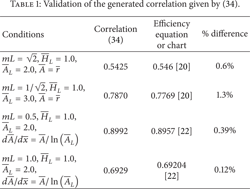
The results of correlation (34) are compared with the results of the fin efficiency equations or charts published in [20, 22] as shown in Table 1. The maximum deviation (relative) between both results is less than 1.5%. This led to great confidence in the generalized correlations (31)–(35).
Validation of the generated correlation given by (34).
Heat transfer through various candidates for high performance fins was mathematically analyzed. Three types were considered: (A) fins of constant cross-sectional area, (B) fins of constant cross-sectional area gradient, and (C) radial fins with power-law cross-sectional area distribution. The fins of types (A) and (B) are allowed to have a variable power-law profile distribution. Exact analytical solutions for the temperature fields were obtained by solving the appropriate fin equations. Accordingly, different performance indicators including the fin efficiency were computed. It was identified from this study that high performance fins are those fins having larger tip cross-sectional areas, larger fin surface areas, and smaller tip thickness than those of the straight fin. These effects tend to increase the fin heat transfer rate above that for the straight fin. Moreover, one of the performance indicators of the fins of type (A) were found to be almost independent on tip thickness when it is smaller than the base thickness and for thermal lengths larger than 1.5. Eventually, the type (C) fins were found to permit more heat transfer rates than the type (B) fins under same tip cross-sectional area and tip thickness. Finally, generalized correlations for the efficiency of high performance fins as function of base area, tip area, base thickness, tip thickness, surface area, and the thermal length were proposed and validated.
Footnotes
Nomenclature
References
1.
BerglesA. E., “The implications and challenges of enhanced heat tranfer for the chemical process industries,”Chemical Engineering Research and Design, vol. 79, no. 4, pp. 437–444, 2001.
2.
NesisE. I.ShatalovA. F., and KarmatskiiN. P., “Dependence of the heat transfer coefficient on the vibration amplitude and frequency of a vertical thin heater,”Journal of Engineering Physics and Thermophysics, vol. 67, no. 1–2, pp. 696–698, 1994.
3.
HaggeJ. K. and JunkhanG. H., “Experimental study of a method of mechanical augmentation of convective heat transfer in air,” HTL3, ISU-ERI-Ames-74158, Iowa State University, Ames, Iowa, USA, 1975.
4.
KaysW. M., “Pin-fin heat-exchanger surfaces,”Journal of Heat Transfer, vol. 77, pp. 471–483, 1955.
5.
KernD. O. and KrausA. D., Extended Surface Heat Transfer, McGraw-Hill, New York, NY, USA, 1972.
6.
BerglesA. E., Handbook of Heat Transfer, McGraw-Hill, New York, NY, USA, 3rd edition, 1998.
7.
HarperD. R. and BrownW. B., “Mathematical equations for heat conduction in the fins of air cooled engines,” NACA Rep 158, National Committee on Aeronautics, Washington, DC, USA, 1922.
8.
MurrayW. M., “Heat transfer through an annular disk or fin of uniform thickness,”Journal of Applied Mechanics, vol. 60, pp. A78–A81, 1938.
9.
KrausA. D.AzizA., and WeltyJ. R., Extended Surface Heat Transfer, John Wiley & Sons, New York, NY, USA, 2001.
10.
GardnerK. A., “Efficiency of extended surface,”Transactions of the American Society for Engineers, vol. 67, pp. 621–631, 1945.
11.
KakacS.PramuanjaroenkijA., and LiuH., Heat Exchangers: Selection, Rating, and Thermal Design, CRC Press, Boca Raton, Fla, USA, 2012.
12.
DíezL. I.CampoA., and CortésC., “Quick design of truncated pin fins of hyperbolic profile for heat-sink applications by using shortened power series,”Applied Thermal Engineering, vol. 29, no. 5–6, pp. 815–821, 2009.
13.
KhaledA.-R. A., “Mathematical extrapolating of highly efficient fin systems,”Mathematical Problems in Engineering, vol. 2011, Article ID 909410, 18 pages, 2011.
14.
ChangY. J. and WangC. C., “A generalized heat transfer correlation for louver fin geometry,”International Journal of Heat and Mass Transfer, vol. 40, no. 3, pp. 533–544, 1997.
15.
RajabiA., “Homotopy perturbation method for fin efficiency of convective straight fins with temperature-dependent thermal conductivity,”Physics Letters A, vol. 364, no. 1, pp. 33–37, 2007.
16.
KhaniF. and AzizA., “Thermal analysis of a longitudinal trapezoidal fin with temperature-dependent thermal conductivity and heat transfer coefficient,”Communications in Nonlinear Science and Numerical Simulation, vol. 15, no. 3, pp. 590–601, 2010.
17.
MinJ.TaoT., and PengX., “Efficiency of fins used in a finned oval tube heat exchanger,”Journal of Enhanced Heat Transfer, vol. 10, no. 3, pp. 323–334, 2003.
18.
GoldsteinR. J.IbeleW. E.PatankarS. V., “Heat transfer— a review of 2004 literature,”International Journal of Heat and Mass Transfer, vol. 53, no. 21–22, pp. 4343–4396, 2010.
19.
GoldsteinR. J.IbeleW. E.PatankarS. V., “Heat transfer— a review of 2005 literature,”International Journal of Heat and Mass Transfer, vol. 53, no. 21–22, pp. 4397–4447, 2010.
20.
IncorperaF. P.DeWittD. P.BergmanT. L., and LavineA. S., Fundamentals of Heat and Mass Transfer, John Wiley & Sons, New York, NY, USA, 2006.
21.
KreyszigE., Advanced Engineering Mathematics, John Wiley & Sons, New York, NY, USA, 2007.
22.
KhaledA.-R. A., “Thermal characterizations of exponential fin systems,”Mathematical Problems in Engineering, vol. 2010, Article ID 765729, 19 pages, 2010.