
Abstract
The IEEE Wireless Access for Vehicular Environment (WAVE) standard consists of the IEEE 802.11p and the IEEE 1609 specifications supporting fast link establishment as well as broadband data communication in vehicular environment. Although the standard has been widely accepted by industry as well as highway authorities in many countries to be used for the radio communication infrastructure of the next-generation Intelligent Transport System (ITS), it remains open for further enhancements such as seamless handover support. This paper presents two proactive caching and forwarding schemes for seamless handover in IEEE WAVE networks: one for straight highway sections and the other for crossroads and junctions. Practical and efficient handover procedures, based on the proposed schemes, are also presented. Specifically, an on-board unit (OBU) informs the old road-side unit (RSU) about its departure from the coverage area such that the old RSU can forward the buffered packets to candidate RSUs for proactive caching. In handover scenarios around crossroads and junctions, the IEEE 802.11f Move-notify message is used by the new RSU to request the rest of candidate RSUs to purge the cached packets in order to prevent the waste of radio resource. Simulation results show that the proposed schemes outperform conventional schemes.
1. Introduction
Thanks to the recent advances in various technologies including wireless communication, sensors, controllers, and hardware and software platforms, traveling in a car is becoming safer than ever as vehicles and roads are always connected and cooperatively exchange safety-related information. The IEEE WAVE is a suite of specifications for wireless access in ITS which comprises of the IEEE 802.11p and the IEEE 1609 supporting fast link establishment as well as broadband data communication of the maximum 27 Mbps between an OBU installed in a car moving at the maximum speed of 200 Km/h and an RSU deployed along roadways [1].
According to the specification of IEEE WAVE, the size of a safety-related application message is limited by a WAVE short message (WSM), which is defined to be 1,400 bytes. This allows the transmission of a WAVE message to be completed while a vehicle moves under the radio coverage of a single RSU. As a result, handover has been excluded from the specification. On the other hand, multimedia applications such as live highway CCTV video clips and Internet browsing, in which a sequence of multiple MAC protocol data units (MPDUs) is transmitted, require handover. Consequently, a growing amount of interest is being drawn towards seamless handover procedures in WAVE systems. Although there exists a basic handover operation described in the IEEE 802.11 specification, it cannot be used by the IEEE WAVE systems because it requires channel scanning, reassociation, and reauthentication procedures which have been excluded from the IEEE 802.11p specification in favor of instantaneous establishment of physical links between RSUs and OBUs.
A small number of research works exist in the literature that propose to use polling operations as means for an OBU to inform its presence under a new RSU (nRSU) in order to support handover procedure in the IEEE WAVE system [2, 3]. Using polling operations is however equivalent to using the reassociation operations and hence is contrary to the design philosophies of the IEEE 802.11p specification. Another drawback of this approach is that handover delay may become very large in case that the OBU fails to receive a poll message or multiple OBUs attempt to send the association messages nearly simultaneously.
One might also consider adopting the basic handover scheme of the IEEE 802.11 standard in order to provide an IEEE WAVE network with handover operations. In this case, the delay performance of the IEEE 802.11 basic handover can be improved by adopting fast handover schemes defined in the amendment specifications such as IEEE 802.11 f/r which support fast handover by reducing the delay in performing QoS negotiation as well as reassociation and reauthentication with a new AP [4, 5]. In addition, some proactive caching and forwarding schemes, which attempt to make the old APs send the MS's context information to the target APs before the link to the old AP breaks, can be considered [6–9]. Many of these schemes also try to choose a minimal number of target APs based on its location, direction, and neighbor graphs such that the overheads in proactive caching and forwarding can be reduced [10–15]. These approaches can be further improved by taking advantage of the regular mobility patterns of vehicles moving on highways such that proactive caching operation of data packets at the nRSU can be simplified and performed efficiently. Around junctions and crossroads, where several candidate nRSU exist, the proactive caching operations can be performed with a limited amount of overhead in terms of radio resource usage. In this paper, we propose efficient proactive caching and forwarding schemes for the IEEE WAVE networks based on the design concepts described above.
This paper is organized as follows. In Section 2, we give a brief background on the related technologies. Section 3 explains the proposed scheme in detail. Section 4 describes simulation setup along with the simulation results. We finish our discussion with some concluding remarks.
2. Background
2.1. The IEEE 802.11p/P1609
The IEEE 802.11p and the IEEE P1609 standards, which comprise the IEEE WAVE standards, have been developed as the wireless communication technology for ITS in North America. It operates in the 75 MHz bandwidth at 5.850–5.925 GHz frequency band. One of the the seven channels of 10 MHz band is assigned as the control channel (CCH) whose main usage is transmission of control and management messages including WSA (WAVE Service Announcement) messages (beacons) and broadcast of safety-related data. The other six channels are used as service channels (SCHs) used for nonsafety-related data including general Internet service.
The CCH and SCH interval of 50 ms each alternates to form a synch interval. The medium access procedure is based on the IEEE 802.11e priority access with random backoff. According to the specification of IEEE P1609.3, data packet transmission is allowed within a WAVE Basic Service Set (WBSS). An OBU or an RSU joins a WBSS as a user. A service provider broadcasts a WSA message periodically on CCH for all persistent services belonging to the WBSS. This message contains all the information identifying WAVE applications as well as link parameters used by an RSU to join the WBSS (e.g., the ID of the WBSS, the SCH this WBSS will use, and timing information for synchronization purposes). When an OBU joins a WBSS via an RSU, it should receive a WSA on CCH to learn about the parameters associated with the WBSS. The OBU may then switch to the WBSSs SCH to join the WBSS and transmit/receive service data frames. Figure 1 illustrates channel access process of IEEE P1609.4/IEEE 802.11p MAC.
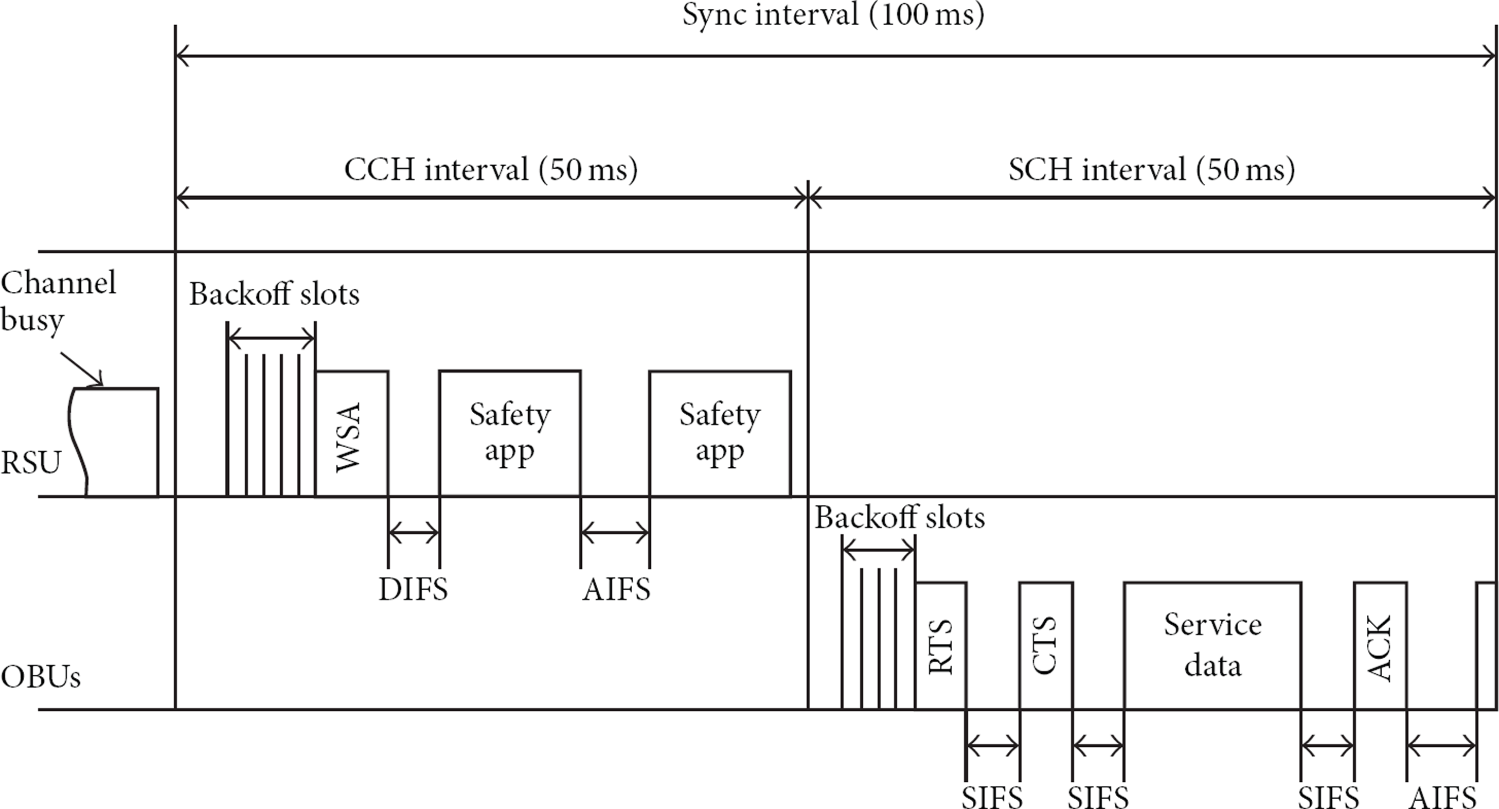
Channel access procedure for the IEEE 802.11p.
According to the IEEE 802.11 specification, there are four address fields in a frame that can be used to deliver the frame via DS (Distribution System). The IEEE P1609.3 specifies three WAVE packet transmission scenarios; that is, packets passed only through WAVE links (e.g., V2V packets), packets generated by an OBU and delivered to a host via a DS, and packets generated by the host and delivered to the OBU via a DS. The use of the four addresses in the MAC header is summarized for the WAVE application in Table 1. Note that the transmission of a packet between two RSUs in the DS (To DS = 1 and From DS = 1) is not explicitly specified in the standard.
IEEE P1609.3 WAVE four-address scheme.
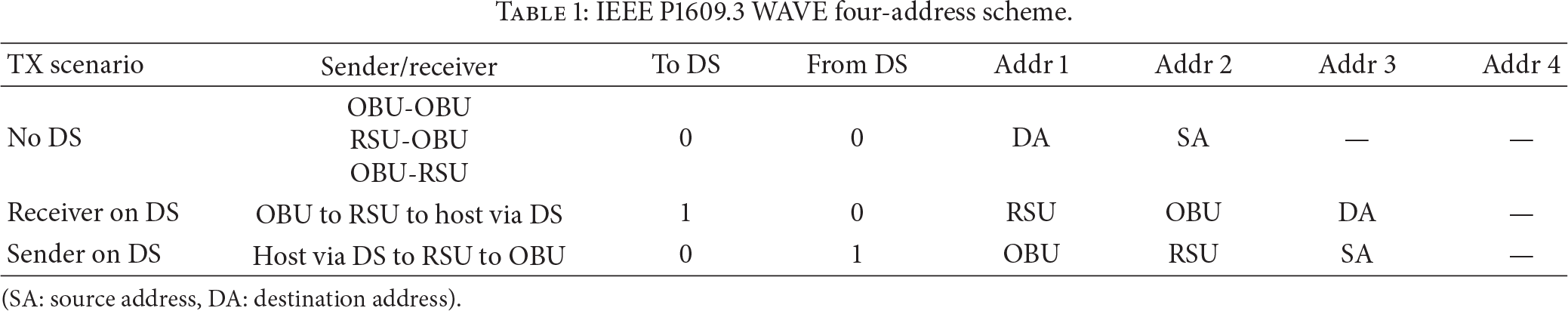
(SA: source address, DA: destination address).
2.2. The IEEE 802.11f Interaccess Point Protocol (IAPP)
The IAPP is designed to facilitate two key functions during a STA's (station's) handover between two APs: maintaining a STA's association with a single AP and the secure transfer of context information between the two APs involved in the handoff. When an STA changes its association with a new AP, the new AP sends a Move-Notify message to the old AP announcing that the STA is now associated with the new AP. This message can also be used by the new AP to request context information such as IP flow-related data, security-related data, and QoS parameters. The old AP can remove the STA's context information from its association table and responds with a Move-Response message. A secure connection between APs can be obtained at the beginning of a reassociation by exchanging a Security Block message with the help of a RADIUS server based on shared keys. When an STA makes the initial connection with an AP, the AP broadcasts an Add-Notify message to all APs within the same ESS informing the STA's association. The APs that receive this message clear the context information from their association tables in order to ensure the single association of the STA with an AP. The IAPP also provides Cache-Notify/Response message for an AP to proactively transfer a STA's context information to the neighboring APs before a handover begins. Figure 2 illustrates the message exchanges during a handover with the IAPP.

Message exchange procedure for IAPP.
3. Proposed Proactive Caching Schemes
3.1. Network Architecture
We assume that the network that constitutes the DS is organized in a tree topology with a hierarchy of learning L2 switches or IEEE 802.1D bridges that are connected to a gateway router at the root and to the RSUs at the leaves. In this network architecture, data frames are transported using MAC addresses. The switches or bridges forward frames according to the filter table entries updated by reading the source and destination MAC address of all frames that pass through them. If an entry for the destination MAC address is not found in the filter table, the frame is flooded though all of the ports except for the input port. It should be noted that the downstream path from the gateway router to an OBU can be created and maintained by outbound data frames generated by the OBU or its serving RSU. This simplifies the network mobility management of layer 3 because the entire network appears as a single distribution system with multiple RSUs to the upper layer. Figure 3 gives a conceptual illustration of the network architecture.

Architecture of the IEEE WAVE networks.
3.2. Handover Procedure for the IEEE WAVE Networks
In general, physical link quality can drop rapidly near the boundary of radio coverage so that the stable reception of data is not guaranteed. Handover takes place when the received signal strength drops below a certain threshold value. An IEEE 802.11 station starts a scanning process to find another AP by tuning into every channel to transmit probe messages and/or receive beacons from the APs. The scanning process may take up to several hundred milliseconds which is too long for seamless handover. Upon determining an AP with the highest link quality, the station changes its association with the newly selected AP. In case of the IEEE WAVE networks, however, the scanning process is unnecessary since an RSU should listen only to the CCH in order to join a WBSS by receiving a WSA message. Therefore, the handover procedure can be greatly simplified for the IEEE WAVE networks.
On the other hand, there is no explicit way for an OBU to make its presence known to the nRSU, since the reassociation/reauthentication operations have been omitted in the IEEE 802.11p standard. This brings up a number of issues such as large delay experienced by other OBUs due to repeated retransmissions to the departing OBU and loss of packets buffered at the old RSU (oRSU). A straightforward approach to address these issues would be to introduce a new management message that is used to inform the nRSU of the OBU's entry into its radio coverage. This approach however has several disadvantages; first, transmitting a management message to a RSU to inform the OBU's entry is equivalent to using the reassociation operations and, hence, is contrary to the design philosophies of the IEEE 802.11p specification, that is, instantaneous link setup in the CCH without reassociation; second, the new message may have to be delayed up to 50 ms until the beginning of SCH interval because the unicast of nonsafety-related data is not allowed in CCH. Note that this delay can be extended up to 150 ms if the OBU fails to receive a WSA message in the first CCH subframe; third, the new messages may suffer from high loss probability due to collisions caused by the same messages transmitted simultaneously by a number of OBUs; fourth, radio resource of the oRSU may still be wasted by retransmissions until it is notified of the RSU's presence under the nRSU.
In this section, a simple but elegant approach to the issues mentioned above is presented. Our approach takes advantage of the highway usage scenarios of WAVE networks, where there are always a limited number of candidate nRSUs. More specifically, there is only one candidate RSU in the case of straight highway sections and there are only a few candidate RSUs around a crossroad or a junction. Therefore, the OBU merely inform the oRSU about its intention to break the connection with the oRSU, such that the rest of data destined to the OBU can be forwarded by the oRSU and proactively cached by the candidate nRSUs even before the OBU begin to receive packets via the nRSU in the next SCH subframe as instructed by a WSA message. In what follows, we explain the two proactive caching and forwarding schemes along with two handover procedures for the two usage scenarios.
3.2.1. Straight Highway Section
In the straight highway usage scenario, the identification of the next RSU can be determined, in advance, based on the identification of the current RSU, since it can be assumed that the RSUs are deployed in an ordered fashion along a highway and the movement of vehicles is unidirectional.
We propose to use the IEEE 802.11 disassociation message to trigger handover procedure. The disassociation message is transmitted in the SCH by an OBU to signal its oRSU of its imminent departure from the coverage to switch to the next RSU. Upon receiving the disassociation message from the OBU, the RSU can stop transmitting data frames destined to the OBU and, instead, forward them to the nRSU for the last-hop transmission to the OBU. This also helps save a significant amount of radio resource by preventing the RSUs from transmitting frames to nonexisting OBUs. The address fields in the MAC header of the forwarded frames are set as follows: both the “From DS” and “To DS” flags are set; Address 1 is set to the nRSU's address; Address 2 is set to the address of the oRSU's address, and Address 3 is set to OBU's address; (or broadcast address). Since this type of address combination is never used for regular data/control frames within a WAVE-enabled network, as explained in Section 2.1, the nRSU can distinguish the forwarded data frames from the other frames. Having received the first forwarded frame from the oRSU, the nRSU recognizes the OBU's entry into its coverage and transmits a null data frame with the OBU's address recorded in Address 3 through the L2 switch-populated backbone network up to the gateway (router) to other networks. This makes all the L2 switches along the path from the gateway router down to the nRSU update their filter table such that the OBU receives all subsequent frames via the nRSU. Since the OBU can receive the forwarded frames only after it receives a WSA message and configures itself according to the information contained in the WSA, the nRSU transmits the forwarded data frames in the beginning of the next SCH.
It should be pointed out that no frames are expected to be lost due to the connection break during a handover, unless the buffer in the nRSU overflows or the nRSU's retransmission count reaches the limit, since the OBU instructs the oRSU to forward the buffered frames to the nRSU. On the other hand, the proactive caching of data frames at the nRSU can cause a head-of-line blocking problem if the cached frames are not sent out from the buffer and transmitted to the OBU in time, which can increase the average frame delay by a significant amount. Protocol overhead is minimal since the only additional frame incurred by the proposed scheme a single disassociation message. Figure 4 shows the message sequence diagram of the handover scheme for straight highway sections.

Message exchange procedure of handover scheme for straight highway sections.
3.2.2. Crossroads and Junctions
As discussed in the previous section, oRSU should be able to identify nRSU for a handover scheme based on proactive caching to operate correctly and efficiently. Therefore, this scheme would fail to work when there are multiple candidate nRSUs as in crossroads and junctions unless a fairly accurate target nRSU prediction scheme is available. There exist a large number of previous works in the literature for determining target base stations based on the mobility prediction of mobile stations for handover in mobile communication systems [16]. Applying traditional location prediction schemes to a practical handover procedure [17, 18] in vehicular environments may not be appropriate because of the relatively large processing delays. Recent studies have analyzed the movement patterns of passengers based on historical data [19–21]. Two types of approaches can currently be observed in existing literature: a microscopic approach and a macroscopic approach. The microscopic approach uses speed, vehicle direction, and road information to estimate the expected destination base station (BS) or AP. This approach is suited to rural environments but is less applicable in metropolitan areas that have many intersections. In contrast, the macroscopic approach continually learns and observes the movement attributes of vehicles, and an estimation of the destination BS or AP is made based on the outcome of such learning. The vehicle movement pattern is ordinarily analyzed based on large amounts of trace data. For instance, by applying PCA (Principal Component Analysis) to original data, the low intrinsic dimensionality can be revealed as Sun et al. utilized PCA to explore the space-time structure of aggregate human mobility [22]. However, this approach not only requires complex mathematical and statistical processing methods to predict movement patterns but it is also difficult to maintain a sufficient amount of trace information for a specific vehicle.
Instead of trying to predict the nRSU, our scheme forwards data packets to all the candidate nRSUs by multicast. A serious drawback of this approach is that all candidate nRSUs attempt to transmit the same packets because there is no way of determining whether the OBU has entered their radio coverage due to the lack of association procedure. This leads to a significant amount of delay as well as waste of radio resource since transmission failure causes repeated retransmissions as specified in the standard. The proposed scheme addresses this issue by making the nRSU notify the other candidate nRSUs that it has become the serving nRSU upon receiving a packet from the OBU. More specifically, the Move-Notify message of the IEEE 802.11f IAPP is used for communication between nRSU and the rest of the candidate RSUs. The nRSU recognizes that the OBU has entered its radio coverage range when it receives the ACK for the first packet forwarded from the oRSU. The nRSU then sends a Move-Notify message to the other RSUs to announce that it has now become the serving nRSU to all other candidate nRSUs. Upon receiving the Move-Notify message, the other nRSUs stop transmitting the cached packets to the OBU and purge the packets from the cache. This prevents repeated retransmissions and hence helps the candidate nRSUs avoid wasting radio resource. The nRSU also sends a null packet with the OBU's address recorded in Address 3 through the L2 switch-populated backbone network up to the gateway in order to make all the L2 switches along the path from the gateway router down to the nRSU update their filter table. The proposed scheme based on the Move-Notify message as summarized in Figure 5.

Message handling procedure of the proposed handover scheme.
In order to use multicast to forward packets to the candidate nRSUs, the multicast address defined in the IEEE 802.11 should be used. This multicast address can be assigned using Internet Group Management Protocol (IGMP). Since the topology of the WAVE networks is not expected to change frequently, multicast addresses can be assigned statically at the time of RSU deployment. In other words, a multicast group can be formed for an RSU and all candidate RSUs and a multicast address can be allocated. Since the multicast address allocation is performed statically, it would not increase the handover delay.
In summary, the main idea of the proposed scheme for seamless handover at crossroads and junctions is similar to that of straight highway segments, that is, data packet forwarding and for proactive caching at the nRSU. The only difference between the two schemes is that the oRSU must now forward packets to multiple candidate nRSUs, instead of a single nRSU. The OBU receives the cached packets only from the nRSU from which it will have received a WSA message. All the other candidate nRSUs are refrained from transmitting the cached packets by receiving a notification of the OBU's handover to the nRSU based on the IEEE 802.11f Move-Notify message. As with the scheme for the straight highway section, the protocol overhead is minimal since the only additional frame generated by the proposed scheme is a single disassociation message.
4. Simulation
4.1. Simulation Setup
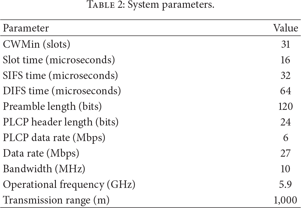
In order to evaluate the performance of the proposed schemes, an extensive set of simulation was carried out using ns-2.28 simulator with the IEEE 802.11e MAC modified to include the operations of the IEEE 802.11p and the proposed handover scheme. Simulation scenarios were set up to reflect the OBUs installed in vehicles moving on highways with RSUs deployed on the shoulders and connected to a L2 switch. Tables 2 and 3 lists some simulation and system parameters used in the simulation.
System parameters.
Simulation parameters.

Figure 6(a) gives the conceptual illustration of the simulation scenarios of the straight highway sections. The network consists of 100 OBUs which move along a highway in two lanes, five RSUs which are fixed on a side of the highway at 2,000 m apart, and an L2 switch which connects the RSUs via an Ethernet. We do not allow for a multitier wired backbone network to exclude the processing and queuing delay effects in the backbone and instead focus on the performance of the proposed schemes within a set of neighboring RSUs. The speeds of OBUs are set to be random within 10% range of 160 km/h and the distances between OBUs are set to be random within 10 m range of 160.
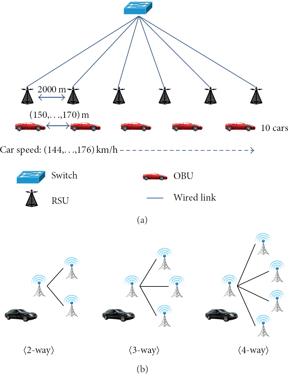
Simulation scenarios. (a) Straight highway section and (b) three types of diverging roads.
Three different scenarios for crossroads and junctions from 2-way to 4-way were used to evaluate the performances while varying the number of vehicles, from one to five, diverging in each direction (Figure 6(b)). In each simulation scenario, all vehicles that were lined up with a random intervehicular distance of 80~120 m started to move towards RSU #1 at a random speed in the range of 140~180 Km/h. In all cases, the number of vehicles in each direction after divergence is the same and handover occurs only once. The data flow is a video stream of priority 1 (AC_VI) transmitted at the rate of approximately 823 Kbps with the packet size of 1,144 bytes and the variable packet intervals.
4.2. Simulation Results
4.2.1. Straight Highway Section
We compare the performance of the proposed handover scheme to that of a poll-based scheme which is similar to the scheme presented in [19]. In the poll-based scheme, the OBU transmits a poll message destined to the gateway router, upon reception of a WSA message, in order to inform the nRSU of its presence and force all of the upstream L2 switches to update their filter tables for the potential change of a downlink path from the gateway router the nRSU. Upon receiving the poll message, the nRSU sends a Move-notify message to request the oRSU to send the buffered data frames. Simulations are repeated with different values of the inter-RSU distances in order to study the effect of handover delay on the performance of application in terms of average packet delay, throughput and handover delay.
It should be noted that the inter-RSU distance of less than 2,000 m results in a partly overlapped RSU radio coverage. There are two kinds of traffic flows and each OBU receives a single traffic flow during an entire simulation period. One of the traffic flows is a CBR traffic of the priority 2 (AC_BE) with transmitted at the rate of 8 Kbps, with the packet size of 100 bytes and the packet interval of 100 ms. The other flow is a video stream of priority 1 (AC_VI) transmitted at the rate of approximately 823 Kbps with the packet size of 1,144 bytes and the variable packet intervals. The number OBUs receiving CBR traffic flows and video streams are the same.
The average packet delay is calculated by dividing the total transmission delay by the total number of packet transmission and the throughput is calculated by dividing the total amount of transmitted data by the total transmission time. The handover delay is calculated by measuring the interval between the moment that an OBU receives the last data frame from the oRSU and the moment that the OBU receives the first data frame from the nRSU.
In the simulations, we varied the inter-RSU distance by 5 m from 1,990 m to 2,010 m in order to study the performance of proactive caching used in the proposed handover protocol. Since the distance that a vehicle can move in 100 ms is approximately 4.4 m, the OBU should wait for the next SCH to receive a frame from the nRSU.
All four graphs show that the performances of the two schemes remain approximately the same when the inter-RSU distance is less than 2,000 m. This is because the OBU receives data frames in the immediate next SCH of the nRSU after it fails to receive a frame from the oRSU, and the length of handover delay is too short to benefit from the proactive caching. As the inter-RSU distance increases to 2,000 m and higher, the proposed scheme starts to outperform the poll-based scheme thanks to the proactive caching. Figure 7(a) shows that the average packet delay increases by a significant amount in the case of proposed scheme indicating that more packets are delivered to the OBU by the nRSU delayed by a certain amount of time. It should be noted that the dropped packets are excluded in calculating delay. As shown in Figure 7(b), the throughput of the proposed scheme is higher for the proposed scheme. Figure 7(c) shows shorter handover delay achieved by the proposed scheme. Namely, the OBU begins to receive the buffered frames from the nRSU immediately after receiving a WSA message according to the proposed scheme, whereas the IEEE 802.11p with poll scheme should first send a poll message to bring the buffered frames in the oRSU. A significant number of these packets are removed due to the retransmission limit. This is reflected in Figure 7(d) as the lower delivery ratio for the IEEE 802.11p with poll messages.

Performance of the proposed scheme and the poll-based scheme.
4.2.2. Crossroads and Junctions
In each simulation run, network throughput, average throughput per node, average end-to-end packet delay, average handover delay, and packet delivery ratio were measured. Unlike the case of straight highway sections, here we focus on the performance improvement achieved by sending Move-Notify messages to the other candidate nRSUs in order to prevent them from repeatedly retransmitting cached data packets. This would result in more efficient use of radio resource and, hence, superior performance. In order to compare the performance of the proposed scheme to another scheme, ns-2 module for a simple multicast-based proactive caching scheme was implemented. As illustrated by the graphs in Figures 8(a) and 8(b), both the system and per-node throughput performances of the proposed scheme are superior to the simple multicast-based scheme. It can be clearly noticed that the throughput saturates rapidly when multicast-based scheme is used for 4-way diverging roadways, in which there are up to 15 vehicles in total entering the coverage of the candidate nRSUs causing a significant amount of the wasteful consumption of radio resource by the repeated retransmission of cached packets as described above.
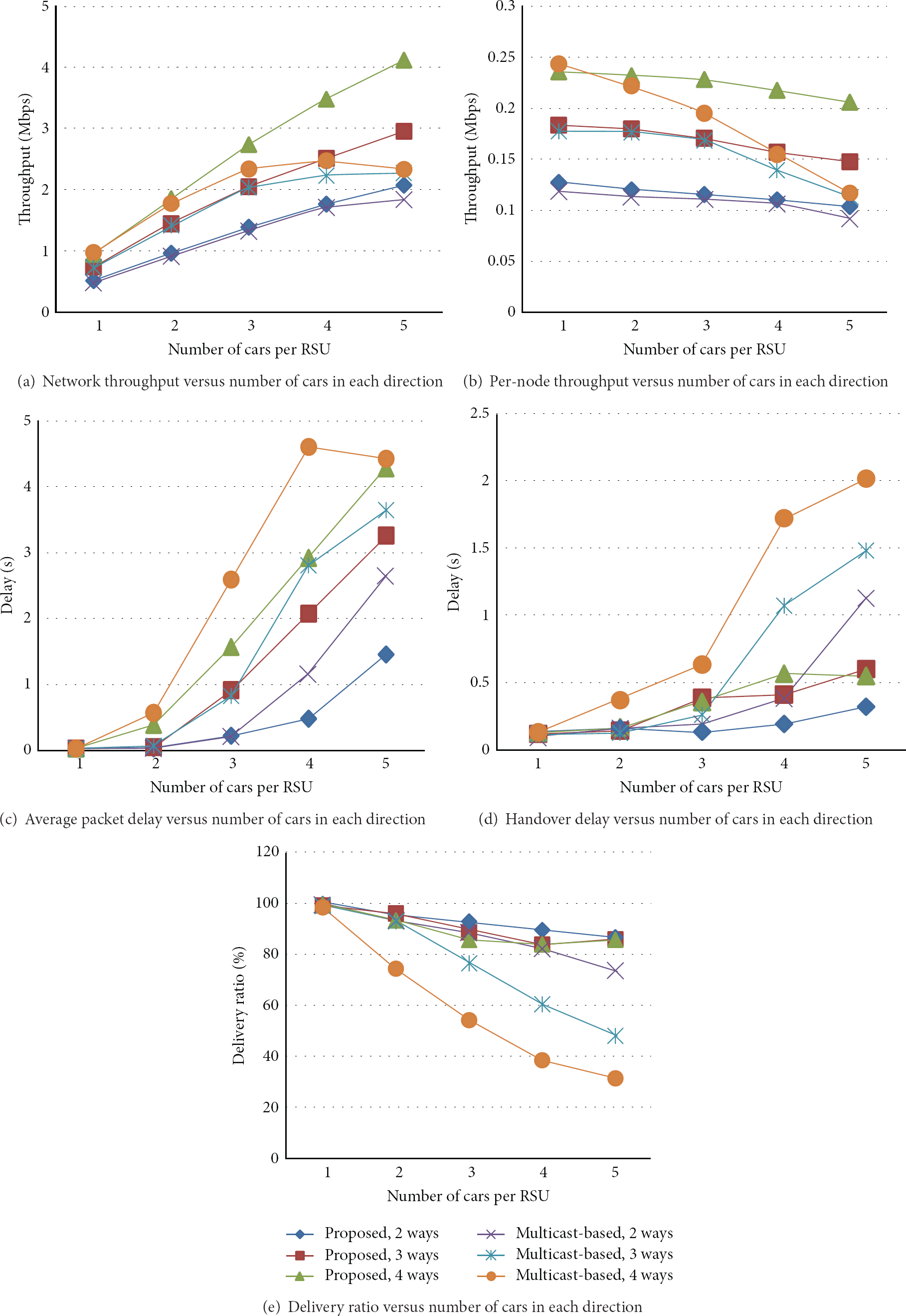
Performance of proposed scheme and simple multicast-based scheme.
In Figure 8(c), one can notice that the proposed scheme outperforms the simple multicast-based scheme in terms of average end-to-end packet delay in all scenarios. This again confirms the effectiveness of preventing retransmissions of the cached packets by Move-Notify messages as in the throughput results. The values on the curves are large in this graph because both the cached packets as well as the packets from the DS are delayed for a long period of time in the interface queue before the candidate nRSUs remove the cached packets from the interface queues.
Similar observations can be made with handover delay as in Figure 8(d). Handover delay is the time difference between the last packet reception under the oRSU and the first packet reception under the nRSU for the same data flow, and it is mainly affected by the time spent in the interface queue of the nRSU. Since an RSU can be an nRSU for a vehicle but a candidate nRSU for the other vehicles at the same time, its interface queues are quickly populated by the cached packets forwarded by the oRSU, and hence handover delay increases rapidly.
In many cases, the length of interface queues becomes so large that overflows occur, which lead to a lower packet delivery ratio as shown in Figure 8(e). As described earlier, the proposed scheme removes all cached packets in candidate nRSUs from its interface queue upon receiving a Move-Notify message. The simulation results confirm that this helps reduce the packet loss due to the congested queue significantly.
5. Conclusion
In this paper, we proposed a novel seamless handover scheme for the IEEE 802.11p-based networks deployed along a highway with straight sections and crossroads. The proposed scheme uses multicast to forward data packets to all candidate RSUs for proactive caching. The nRSU sends IEEE 802.11f Move-Notify messages to the other candidate RSU such that they can avoid waste of radio resources caused by repeated retransmissions of data packets. This paper gave a brief overview on the related technologies and explained the proposed scheme in detail. We described simulation setup along with the simulation results. The simulation result showed that proposed scheme have lower end-to-end and handover delay and higher throughput and delivery ratio than conventional proactive caching schemes.
We plan to carry out additional simulations to compare the performance of proposed scheme with a handover scheme based on mobility prediction. As a future study, we will further enhance the performance of proposed scheme by exploiting mobility model generated by user profiles as well.
Footnotes
Acknowledgments
This work was supported by the National Research Foundation of Korea (NRF) Grant funded by the Korea government (MEST) (no. 2010-0000281) and was conducted during the sabbatical year of Kwangwoon University in 2012.