
Abstract
The extended study of Wu et al. (2012) of sloshing fluid in tanks with internal structures from 2D to 3D is presented in the paper. The phenomenon of liquid sloshing in a 3D tank with various damping devices is solved by the time-independent finite difference method combined with the ghost (fictitious) cell approach. Two types of damping devices, a tank bottom-mounted baffle and a vertically surface-piercing plate, are considered in the study. In this work, the experimental measurement of liquid sloshing in a 3D tank with the baffle is carried out to further validate the present simulation. The comparison of the results between the experimental measurement and the present computation shows good accuracy. The effect of the vertically tank bottom-mounted baffle or the vertically surface-piercing plate on various sloshing waves for the tank under horizontal oblique excitation is discussed and investigated. The phenomena of the shift of the nature frequency of the tank with damping devices due to various oblique horizontal excitations under different sloshing waves are presented in detail. The sloshing wave type is varied due to the influence of the baffle or the plate, and the coexistence of two types of sloshing waves is found for the tank under larger excitation frequencies.
1. Introduction
Liquid sloshing is the most prominent phenomenon of liquid motion in either stationary or moving tanks subjected to forced external perturbations. The study of sloshing phenomenon in tanks is related to a wide range of applications such as in ships, rockets, satellites, trucks, and even stationary-petroleum containers. Resonant free-surface flows in tanks in aircrafts, missiles, and rockets have been the focus of extensive research. The amplitude of the sloshing, in general, depends on amplitude and frequency of the tank motion, liquid-fill depth, liquid properties, and tank geometry. These parameters have significant effects on the dynamic stability and performance of moving vehicles carrying containers. One of the passive devices to reduce the influence of sloshing impact on structures or suppress the strength of liquid sloshing is inserted in internal obstacles in containers, such as baffles, plates, rings, and wire screens. The tanks mounted with sloshing-damping devices are called Tuned Liquid Damper (TLD).
Tuned Liquid Dampers (TLDs) are economical and effective dynamic vibration absorbers. The main function of a passive damping device is to absorb portion of the input energy associated with external dynamic excitation acting on the structure. Examples for external excitations are wind and earthquakes. By doing so, the passive damping device minimizes or eliminates the possibility of structural damages. TLDs were used to stabilize marine vessels against rocking and rolling motions [1, 2] in offshore platforms [3, 4] and in tall structures [5–9]. Often the TLD is used as a water storage tank preventing the use of a higher-viscosity liquid. Several approaches have been implemented to increase the energy dissipated by the sloshing fluid, including roughness elements [10], surface contaminants [11], wave breaking in shallow water TLDs [12], and nets or screens [7, 13–15]. Akyildiz and Ünal [16, 17] investigated the pressure variations in both baffled and unbaffled rectangular tank numerically and experimentally. They observed that the effects of the vertical baffle are most pronounced in shallow water, and consequently the pressure response is reduced by using the baffles. Liquid viscosity cannot be neglected when flow-damping devices are mounted with a tank with fluid and energy is dissipated by viscous action. Celebi and Akyildiz [18] revealed that flow over a vertical baffle produces a shear layer and energy is dissipated by viscous effect of the fluid. They concluded that, in an increased fill depth, the rolling amplitude and frequency of the tank with or without baffle configurations directly affect the degrees of nonlinearity of the sloshing phenomena. As a result, a phase shift in forces and moments occurred. Armenio and La Rocca [19] adopted the finite difference method to solve the 2-D RANS equations and validated the numerical results with their experimental measurement.
The control of the sloshing behavior with baffles is also a subject of interest in the recent years, because of the complexity and highly nonlinear nature of the problem. Cho and Lee [20] reported a parametric investigation on the two-dimensional nonlinear liquid sloshing in baffled tanks under horizontal forced excitation by using fully nonlinear potential flow theory. In their study, the liquid motion and dynamic pressure variation in the vicinity of the baffle tip are more significant than those below the baffle tip. Cho et al. [21] did a further study on the resonance characteristics of liquid sloshing in a 2D baffled tank under surge motion by the linearized potential flow theory. The various positions, baffle heights, and number of baffles were considered in their work and the fundamental resonant frequency, and the peak elevation of sloshing decreases with these parameters. However, the viscous effect on liquid sloshing could not be resolved based on potential theory. Younes et al. [22] experimentally explored the hydrodynamic damping due to vertical baffle arrangements in a rectangular tank with sloshing fluid. The arrangement of upper-mounted and lower-mounted vertical baffles of different heights and numbers were considered in their experiment. They found that the twin-sided upper mounted baffles and center-holed lower mounted baffle arrangement yield a maximum damping ratio on sloshing. More recently, Akyildiz [23] investigated the effect of the vertical baffle height on liquid sloshing in a rolling 2D rectangular tank, and the nonlinear liquid sloshing was solved by the volume of fluid (VOF) technique. He solved the complete Navier-Stokes equations in primitive variables by using of finite difference approximations with the moving coordinate system. He concluded that the blockage effect of the baffle on the liquid convection is predominant to the tip vortex when the baffle height increases. Wu et al. [24] carried out that the fictitious cell approach associated with a coordinate transformation technique was successfully adopted to solve for the sloshing liquid in 2D tanks with baffles. The numerical scheme was validated by their experiment work. The effects of the number of the baffles on the sloshing amplitude were studied. In the study of two baffles, the largest wave damping might occur when the distance between two baffles is 0.2 L. In addition, the influence of baffle height on the shift of the first natural mode of the baffled tank (ω1) under different water depths is carried out by spectral analyses of sloshing elevation. Several empirical formulas are derived by curve fitting, and they can be used to predict the shift of the fundamental mode of the liquid sloshing in tanks with baffles.
However, the 3D numerical simulation of viscous liquid sloshing in a tank with internal structures is still very limited in the literature. Liu and Lin [25] investigated liquid sloshing in a baffled tank with large-eddy simulation (LES). In their study, the vertical baffle is a more effective tool in reducing the sloshing amplitude. Jung et al. [26] utilized commercial software, ANSYS Fluent, to solve liquid sloshing in a 3D tank with baffles under only lateral excitation. The behavior of tip vortex, free surface elevation depending on the baffle height, and the pressure exerted on the tank wall were discussed in detail.
In the present study, we straightforwardly extend the numerical model of Wu et al. [24] from 2D to 3D to explore sloshing dynamics in tanks with two damping devices, a tank bottom-mounted baffle, and a surface-piercing flat plate. The excitation of a three-dimensional tank (Figure 1) with different dimensionless excitation amplitudes; with multiple degrees of freedom for the excitation direction; with excitation frequencies near and far from the first natural frequency; with arbitrary water depths are considered in this work. In the three-dimensional model, the time-independent finite difference method [24] is utilized to incorporate the 3D Navier-Stokes equations and the fully nonlinear kinematic and dynamic free surface boundary conditions for incompressible fluid in a rectangular tank with a square base. The time varying moving boundary is mapped onto a time-independent domain through proper transformation functions, and a special finite difference approximation is made in order to overcome the difficulty of maintaining the accuracy of the finite difference expression for the second derivative when the difference mesh is stretched near the boundary. The treatment of flow field around flow damping devices is carried out by a fictitious cell approach which is similar to the ghost cell approach [27]. The second order upwind scheme is also used to deal with the convective terms. The main focus of this paper is to discuss the effect of a vertically tank bottom-mounted baffle and a surface-piercing flat plate on the nature modes of various sloshing waves for a tank subjected to oblique horizontal excitation. Not only is the numerical simulation studied in this work, the experiment setup for a tank with a baffle is also investigated to further validate the accuracy of the developed numerical scheme.

Definition sketches of the tank and the coordinate system. (a) A vertically tank bottom-mounted baffle; (b) a vertically surface-piercing flat plate.
Section 2 introduces the equations of motion which are written in a moving frame of reference attached to the accelerating tank. The fully nonlinear free surface boundary conditions are listed in this section. Besides, the fictitious cell approach is implemented to deal with the interfaces of fluid and structure (baffle, tank bottom, and tank walls). The comprehensive benchmark tests of the present numerical scheme are demonstrated in Section 3. The detailed influences of the flow damping devices on various sloshing waves are also dissected in this section. Section 4 summarizes the key conclusions.
2. Mathematical Formulation
In this work, the sloshing phenomenon in a rigid 3D tank with partially filled liquid is analyzed, and two flow damping devices, a vertically tank bottom-mounted baffle, and a surface-piercing flat plate are considered. As illustrated in Figure 1, the breadth of the tank is L, the tank's width is B, and d0 is the still liquid depth. d b is the baffle height, and P L is the width of the plate. The gas flow including the possibility of gas pockets is neglected. The horizontal oblique excitation angle θ is measured between the excitation direction and x-coordinate. The laminar flow is assumed, and the Navier-Stokes equations in a tank-fixed coordinate system can be expressed as

where u, v, and w are the relative velocity components in x, y, and z directions,
The continuity equation for incompressible flow is

Taking partial derivatives of (1) with respect to x, y, and z, respectively, and summing the results, one can obtain the following equation to solve for the pressure:

2.1. Boundary Conditions
We assume that the surface tension effect is neglected. The kinematic condition states that the liquid particles at free surface remain on the free surface and can be expressed as

where η = h(x, z, t) – d0 is the elevation of free surface measured from the initial liquid depth. The dynamic condition requires that the normal stress is equal to the atmospheric pressure, and the two tangential stresses are zero along the free surface boundary. The dimensionless dynamic conditions can, then, be derived and expressed as follows:
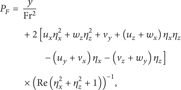

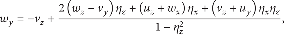
where Fr is the Froude number and Re is the Reynolds number that are defined as
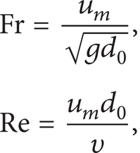
where u m = ωa0 (ω is the angular velocity, and a0 is the excitation displacement of the tank) is the maximum velocity of the tank, η x denotes a partial derivative of η with respect to x, and the others have same meanings. In the present study, (5) is used to determine the hydrodynamic pressure at the free surface, while (6) and (7) are used to extrapolate the horizontal velocity (u, w) at the free surface from the flow domain.
2.2. The Coordinate Transformation and Computational Algorithm
As well known, the way of accurately predicting free surface elevation in 3D tanks with external forcing is still a big challenge due to time dependence of free surface, especially when flow damping devices are involved and coupled with the sloshing flow. In the present study, we extend the numerical scheme of [24] from 2D to 3D by using simple mapping functions to remove the time dependence of the free surface of the liquid domain. The time-varying liquid surface can be mapped onto a cube by the proper coordinate transformations. The convenience of coordinate transformation is to map a wavy and time-dependent liquid domain onto a time-independent unit cubic domain. As listed in Figure 1, the distance from the tank west wall to the baffle (plate) center is X b and from the south wall to the baffle (plate) center is Z b , and the baffle height is Y b . We divide the liquid domain into eight parts based on the location and the height of the baffle or plate. The mapping functions of coordinate transformation of eight parts can be expressed as

Through the mapping functions in (9), one can transform the west wall to x1* = 0, the baffle (plate) center to x1* = 1 and x2* = 0, the east wall to x2* = 1, the free surface to y1* = 0, the baffle tip to y1* = 1 and y2* = 0, the tank bottom to y2* = 1, the south wall z1* = 0 to the baffle center to z1* = 1 and z2* = 0, and the north wall to z2* = 1. In this way, the computational domain is invariant (eight unit squares), and the more advantage of the transformations is to deal with the tank with internal structures of various positions and scales and to avoid the internal structure surrounded by the irregular meshes. Furthermore, combining with the stretching technique [28], the stretching grids can be arranged around the structure boundaries with the sharp corners. The thickness of the baffle or plate is set only at 1% of the tank's length and is, therefore, negligible compared with the length of the tank.
In this three-dimensional analysis, the liquid flow is solved in a unit cubic mesh in the transformed flow domain. All computations use the dimensionless equations in the X-Y-Z coordinate system. All the numerical results presented in this work are in the dimensionless form [28], and the dimensionless equations can be referred to [24, 29] that are omitted in the text. Central difference approximations are used for the space derivatives, except at the boundary where the fictitious cell approach [24, 27] is employed. A staggered grid system is used in the analysis. That is, the pressure P is defined at the centre of a finite difference grid cell (of dimensions (ΔX, ΔY, and ΔZ)), whereas the velocity components U, V, and W are calculated 0.5ΔX, 0.5ΔY, and 0.5ΔZ behind, above, or backward of the cell centre. The Crank-Nicholson second order finite difference scheme and the Gauss-Seidel point successive overrelaxation iterative procedure are used to calculate the velocity and pressure, respectively. The detailed numerical scheme is similar to that reported [24, 28, 29] and is omitted here.
3. Results and Discussion
3.1. Experiment Investigation
It is difficult to be solved by theoretical and numerical studies that the complex and intricate phenomenon of the nonlinearity behavior of resonant sloshing waves occur. The experimental investigation of sloshing with damping devices is very limited and mostly focuses on lateral excitation (only surge motion). In reality, as the tank is excited by accelerations due to an earthquake or waves, the excitation directions of the tank are varied with time. In view of this, an experiment was conceived and attempted to carry out the preliminary investigation on the effect of damping devices on sloshing in tanks subjected to various horizontal excitation angles and to further validate the accuracy of the present numerical work.
The photograph of the experiment setup is shown in Figure 2. The excitation direction of shaking table is designed to be altered by an aluminum alloy rotational table. The material of the baffled tank is acryl with 20 mm thickness to prevent the tank deformation from the hydrostatic pressure and hydrodynamic impact of the liquid, and that of the baffle is fibreglass that can avoid the occurrence of baffle deformation due to hydrodynamic forces. The maximum moving distance (r) of the shaking table is ±30 mm, and the highest revolution of the motor is 2000 r.p.m. The frequency level depends on the limitation of the maximum velocity implemented by the AC motor and the motor reducer. In this experiment work, the maximum velocity (V m = ωr) of the shaking table is about 30 mm/s which indicates that if the excitation displacement (r) becomes large, the corresponding excitation frequency has to be reduced. The measurement of wave elevation is carried out by wave probes, and the locations of wave probes, P1 and P2, are depicted in Figure 3. The comparison of wave history at P1 between the experimental measurement and the present numerical scheme for a baffled tank subjected to an oblique excitation of 15° is illustrated in Figure 4, and a good agreement is demonstrated.

Photograph of the experiment setup of a baffled tank.

Positions of the wave probes from the top view of the baffled tank. Measurements in cm.

The comparison between the results of experimental measurement and those of numerical simulation in a baffled tank; d0/L = 0.5,
3.2. Effect of a Vertically Tank Bottom-Mounted Baffle on Shift of Nature Modes of Sloshing Waves
In this section, the effect of a vertically tank bottom-mounted baffle parallel to the tank breadth (B) on shift of the nature modes of a tank with liquid is discussed. The natural modes (ω i, j ) of 3-D tank can be expressed as
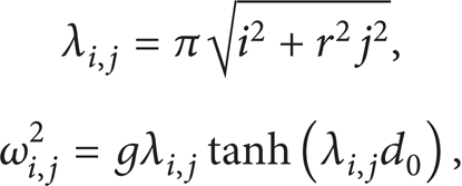
where i, j are the natural mode's components of x- and z-axes, respectively. Wu et al. [24] analyzed the influence of baffle height on the shift of natural modes in 2D tanks with sloshing fluid and concluded that the shift of the lowest natural mode ω1,0 of the tank apparently increases with the growth of baffle height. For the present design of 3D baffled tank, the effect of baffle height on the shift of the lowest natural mode is similar to that in the 2D baffled tank. In other words, the baffle has no influence on the nature mode system in the z-direction. As a 3D baffled tank is subjected to oblique horizontal excitation, the coupled effect of nature modes of sloshing waves will be triggered. Wu and Chen [28, 29] reported that the types of sloshing waves in a 3D tank under various excitation angles and frequencies are the single-directional wave, square-like wave, swirling wave, and irregular wave, and these waves can be triggered by the specific excited frequencies of 0.9ω1, 1.5ω1, 1.0ω1, and 2ω1, respectively. In the following subsections, the effect of the baffle of a fixed height d b = 0.5d0 on the shift of natural modes of different types of sloshing waves for a 3D tank under oblique excitation is discussed in detail.
3.2.1. Effect of Baffle on Single-Directional Waves (0.9ω1)
For an unbaffled tank under coupled surge-sway motion with an excitation frequency of 0.9ω1, single-directional waves appear at an excitation angle of 5°, and diagonal waves occur at θ = 45° [28]. The wave histories of points A (HA) and B (HB), sloshing wave patterns, and the distribution of absolute peaks of the single-directional waves affected by the baffle for a tank with

The effect of the baffle on the single-directional waves. The wave histories of points A and B, (a) θ = 5°; (b) θ = 45°; the wave pattern, (c) θ = 5°; (d) θ = 45°; the distribution of absolute peaks: the locations of the max peaks of the instantaneous free surface, (e) θ = 5°; (f) θ = 45°;
For the results of diagonal waves affected by the baffle, the sloshing elevation of points A (HA) and B (HB) shown in Figure 5 (b) presents a beating phenomenon with different periods. Nevertheless, HB should be very small compared to HA for diagonal waves [28]. This indicates that the wave type of sloshing waves is varied due to the influence of the baffle. The further evidence of switching the wave type of diagonal waves is demonstrated in Figures 5 (d) and 5 (f). The wave pattern (Figure 5 (d)) and the distribution of peaks (Figure 5 (f)) are different from those of the diagonal waves (the inserted plots), whereas they seem to correlate with the swirling waves. From the observation of the snapshots of the free surface (not presented here), the clockwise swirling waves appear after T = 10, and the shift direction of the swirling waves occurs as well. Besides, the period of the counter-clockwise swirling waves is very short compared to that of the clockwise swirling waves. That is, the dominant direction of the swirling waves is clockwise. The reason of this phenomenon can be explained by the effect of the baffle. Imagine that when the wave sloshes from the corner A to corner C, the diagonal flow in the vicinity of the baffle mounted on the tank bottom would transgress the baffle or be conducted along the baffle in a direction from south to north. On the other hand, the liquid particles surrounding the baffle would be directed in a north-to-south direction when the wave sloshes back. The tendency of clockwise rotation of the flow caused by the baffle gradually influences the diagonal waves and then turns the waves into the swirling waves.
The sloshing amplitudes of points A and B depicted in Figure 5 (b) show several beating waves contributed by three modes, 0.9ω1, 0.927ω1, and 1.0ω1, according to the spectral analysis of HA illustrated in Figure 10 (a). Furthermore, the modes of HA presented in Figure 10 (a) are varied with the alteration of the excitation angle of the baffled tank. In other words, the mode, 1.0ω1, appears when the oblique excitation direction changes from 5° to 45°. As discussed earlier, the influence of the baffle height on the reduction of the first resonant mode for this kind of baffled tank is predominantly in the x-direction. When the oblique excitation angle is small (θ = 5°), the wave principally sloshes in the x-direction, and as a result, the shift of ω1,0 is of significance. Based on the observation mentioned above, the modes of 0.927ω1,0 and 1.0ω0,1 can be correlated to the first resonant mode in the longitudinal (x) and the transversal (z) directions of the baffled tank, respectively.
3.2.2. Effect of Baffle on Swirling Wave (1.0ω1)
For a 3D tank without baffles under a resonant excited frequency = 1.0ω1 and an oblique horizontal excitation direction θ = 5°, the swirling wave can be generated. As a tank bottom-mounted baffle is involved, the beating phenomenon of the swirling waves in a baffled tank is presented in Figure 6 (a), and the elevations of points A and B increase with the sloshing periods that indicate that the tank is under a near-resonant excitation. According to the result of spectral analysis of HA shown in Figure 10 (b), two peaks, 0.927ω1 and 1.0ω1, occur, and the dominant one is the external excitation frequency, which is equal to the first natural mode in the z-direction. The growth of the sloshing elevation is, therefore, mainly influenced by the dominant resonant mode (1.0ω1). As demonstrated in Figure 6 (c), HE is obviously larger than HF, and as a result, an elliptic wave pattern is presented. Besides, the characteristics of the swirling waves are illustrated in Figures 6 (c) and 6 (e) and are different from those of unbaffled tank (the inserted plots).

The effect of the baffle on the swirling waves. The wave histories of points A and B, (a) θ = 5°; (b) θ = 45°; the wave pattern, (c) θ = 5°; (d) θ = 45°; the distribution of peaks (e) θ = 5°; (f) θ = 45°; d0/L = 0.5, d b /d0 = 0.5, a0/L = 0.001, and ω x = ω z = 1.0ω1. The inserts are the results of the unbaffled tank.
When θ = 45°, a resonant sloshing elevation is shown in Figure 6 (b) that goes beyond the limitation of the present numerical scheme after T = 120. In addition, a major peak of 1.0ω1 is presented in the spectral analysis of HA depicted in Figure 10 (b) when θ = 45°. The sloshing elevation, consequently, behaves as a resonant phenomenon induced by the resonant mode of 1.0ω1. Moreover, the swirling waves are difficultly generated for an unbaffled tank under a resonant diagonal excitation (see the inserts of Figures 6 (d) and 6 (f)), whereas it is visibly found for the baffled tank, which is demonstrated in Figure 6 (f). The wave pattern depicted in Figure 6 (d) shows that HE is bigger than HF indicating that the prevailing sloshing amplitude is in the transversal (z) direction.
From the design point of view, the best way in reducing the sloshing amplitude for a tank under a resonant diagonal excitation is to mount a diagonally bottom-mounted baffle from point B to point D. On the other hand, the baffle mounted parallel to the tank width can effectively dampen the sloshing amplitude when the oblique excitation angle is small. As a baffled tank is excited at 1.0ω1 under θ = 10°, 15°, and 30°, the results of wave histories at point A depicted in Figure 7 (a) demonstrate that the smaller the excitation angle, the larger the damping effect caused by the baffle. Additionally, the wave patterns of θ = 10°, 15°, and 30° relative to the swirling waves are illustrated in Figures 7 (b), 7 (c), and 7 (d), respectively. The sloshing elevation in the z-direction becomes more dominant with the increase of the oblique excitation angle of the baffled tank. Moreover, the resonant sloshing phenomenon still occurs at θ = 15° and 30° and is beyond the limitation of the present numerical model.

The effect of the baffle on the swirling waves under different excitation angles. (a) wave histories of point A; (b) wave pattern, θ = 10°; (c) wave pattern, θ = 15°; (d) wave pattern, θ = 30°;
3.2.3. Effect of Baffle on Square-Like Wave (1.5ω1)
The results of the influence of the baffle on the square-like waves under various excitation angles are delineated in Figure 8. When θ = 5°, Figures 8 (a), 8 (c), and 8 (e) show, respectively, the significant effect of the baffle on the sloshing elevation, wave pattern, and the peaks' distribution of the square-like waves compared to those of unbaffled tank. According to the spectral analysis of HA shown in Figure 10 (c), the elevations of points A and B are dominated by two major modes; one is 0.927ω1, and another other is 1.805ω1. The influence of excitation frequency (1.5ω1) on sloshing elevation, however, becomes insignificant. The dominant sloshing elevation of unbaffled tank is in the x-direction (inserted plot of Figure 8 (c)), and it becomes more dominant due to the effect of the baffle. Besides, it is found that the square-like waves and the swirling waves appear together in the simulation. Although two kinds of sloshing waves coexist, the wave type is still dominated by the square-like waves for this case.

The effect of the baffle on the square-like waves. The wave histories of points A and B, (a) θ = 5°; (b) θ = 45°; the wave pattern, (c) θ = 5°; (d) θ = 45°; the distribution of peaks (e) θ = 5°; (f) θ = 45°; d0/L = 0.5, d b /d0 = 0.5, a0/L = 0.001, and ω x = ω z = 1.5ω1. The inserts are the results of the unbaffled tank.
As the oblique excitation angle increases to 45°, the elevation of point A shown in Figure 8 (b) becomes irregular. The reason is, by comparing with that of θ = 5°, two more peaks (1.0ω1 and 1.5ω1) appear in the spectral analysis of HA depicted in Figure 10 (c). Additionally, the spectral density of the mode of 0.927ω1 decreases when θ is switched to 45°. This implies that the influence of the mode of 0.927ω1 on the sloshing amplitude reduces as well. Furthermore, the result of HB presents a beating-like wave. From the spectral analysis of HB (not shown here), the beat wave is contributed by two modes, 0.927ω1 and 1.0ω1. The variation of oblique excitation of the baffled tank, therefore, induces the interchange between the modes of sloshing waves. Furthermore, the coexistence of the square-like waves and the swirling waves is demonstrated in Figures 8 (d) and 8 (f), and the swirling waves of θ = 45° present more predominantly than that of θ = 5°. The reason might be correlated to the tendency of triggering the circulatory flow when θ = 45° is easier than that when θ = 5° due to the effects of the baffle.
3.2.4. Effect of Baffle on Irregular Wave (2.0ω1)
As illustrated in Figure 9, the effect of the baffle on the irregular waves is similar to that on the square-like waves. The shift of the modes due to the variation of excitation angle is demonstrated as well by the result of spectral analysis of HA illustrated in Figure 10 (d). Besides, HB depicted in Figure 9 (b) also presents a beating phenomenon that is induced by 0.927ω1 and 1.0ω1 according to the spectral analysis (not presented here). The irregular waves coexist with the swirling waves, as shown in Figures 9 (e) and 9 (f). For the snapshots of the free surface, the swirling wave occurring at θ = 5° is not as obvious as that at θ = 45° that is similar to the phenomenon found in the results of the square-like waves affected by the baffle. The snapshots of the square-like waves and irregular waves that coexist with the swirling waves are illustrated in Figures 11 and 12, respectively.

The effect of the baffle on the irregular waves. The wave histories of points A and B, (a)θ = 5°; (b) θ = 45°; the wave pattern, (c) θ = 5°; (d) θ = 45°; the distribution of peaks (e) θ = 5°; (f) θ = 45°; d0/L = 0.5, d b /d0 = 0.5, a0/L = 0.001, and ω x = ω z = 2.0ω1. The inserts are the results of the unbaffled tank.

The power spectral analysis of the wave elevation at point A for a baffled tank under various excitation angles. The excitation frequency of the tank (a) 0.9ω1, single-directional waves; (b) 1.0ω1, swirling wave; (c) 1.5ω1, square-like wave; (d) 2.0ω1, irregular wave; d0/L = 0.5, d b /d0 = 0.5, and a0/L = 0.001.

The snapshots of the free surface of a baffled tank;

The snapshots of the free surface of a baffled tank;
3.3. Effect of a Surface-Piercing Flat Plate on Sloshing Waves
In this section, we will explore the effect of a surface-piercing flat plate in a 3D tank on various sloshing waves. As depicted in Figure 1 (b), P L is the length of the plate and is set to 0.4B for all the simulations in this work. The influence of the surface-piercing plate on sloshing dynamics in tanks is definitely different from that of the tank bottom-mounted baffle due to its direct blockage of the free surface. The free surface flow caused by the surface-piercing plate might become more complicated. The shift of the lowest nature mode of the tank with liquid affected by the surface-piercing plate is discussed here as well.
3.3.1. Effect of a Surface-Piercing Flat Plate on Single-Directional Waves (0.9ω1)
The wave histories of points A and B for the single-directional waves affected by the plate are illustrated in Figure 13 (a), and the beating phenomena of HA and HB are unclear, and the sloshing elevation seems to reach a nearly steady state after T = 100. The spectral analysis of HA depicted in Figure 18 (a) shows that two peaks appear when θ = 5°, and the primary peak is 0.91ω1, which is close to the excitation frequency of the tank, and the secondary one (1.79ω1) is almost twice as big as the dominant frequency. Besides, the peak of 0.91ω1 might be in connection with the first natural mode in the x axis due to the effect of the plate. The wave histories of points A and B depicted in Figure 13 (a), therefore, behave as a resonant-like response when θ = 5°. Furthermore, the results of the wave pattern (Figure 13 (c)) and the distribution of peaks (Figure 13 (e)) demonstrate that the waves predominantly slosh in the x-direction. Moreover, the effect of the surface-piercing plate on the free surface is illustrated in the inserted plot of Figure 13 (e). It is apparently seen that two sinks appear close to the corner of the plate on the free surface. These two sinks are 3D vortices induced by free surface flow passing the plate. The vortex sinks are the source of the disturbance on the free surface, which will result in generating more and more complicated free surface wave profiles.

The effect of the plate on the single-directional waves. The wave histories of points A and B, (a) θ = 5°; (b) θ = 45°; the wave pattern, (c) θ = 5°; (d) θ = 45°; the distribution of peaks (e) θ = 5°; (f) θ = 45°; d0/L = 0.5, P
L
/B = 0.4, a0/L = 0.001, and ω
x
= ω
z
= 0.9ω1. The inserts are the instantaneous free surface. Dimensionless elevation H = η/d0 and dimensionless time
When θ = 45°, the elevations of points A and B depicted in Figure 13 (b) show several beating waves attributed to three modes, 0.91ω1, 0.98ω1, and 1.79ω1 based on the spectral analysis of HA illustrated in Figure 18 (a). Furthermore, as depicted in Figure 18 (a), the near-resonant mode of 0.98ω1 appears when the excitation angle switches from 5° to 45°, and therefore, the sloshing elevation increases with time due to the influence of the near-resonant mode (0.98ω1). In addition, the original diagonal wave type is turned into swirling wave type due to the influence of the plate. The phenomenon of 3D sink vortices on the free surface near the plate's corners is presented in the inserted plot of Figure 13 (e) as well, and detailed time history of snapshots of free surface are depicted in Figure 19. Note that the near-resonant mode of 0.98ω1 should be the first natural mode of the plated tank in the z-direction. However, it is not equal to 1.0ω1 which is the first natural mode in the z-direction of the baffled tank as we discussed in Section 3.2.1. The free surface disturbance induced by the plate might be the reason to shift the lowest nature mode in the z-direction of the plated tank.
3.3.2. Effect of a Surface-Piercing Flat Plate on Swirling Waves (1.0ω1)
For a plated tank under a resonant excitation and θ = 5°, the beating phenomenon of the swirling waves is presented in Figure 14 (a), and the elevations of points A and B increase with time. According to the spectral analysis of HA shown in Figure 18 (b), the dominant peak is the external excitation frequency (1.0ω1), which is equal to the first resonant mode in the z-direction, and the secondary peak (0.91ω1) can be correlated with the first natural mode in the x-direction. The growth of the sloshing elevation is, therefore, mainly induced by the dominant resonant mode (1.0ω1), especially in the transversal (z) direction. An elliptic wave pattern depicted in Figure 14 (c) is, therefore, presented due to HE which is larger than HF. Moreover, the clockwise swirling waves appear constantly, and the phenomenon of switch direction of swirling waves disappears. In other words, unlike the effect of the tank bottom-mounted baffle, the surface-piercing plate not only shifts the natural mode system of the tank, but alters the characteristic of the swirling waves. The absolute peaks of clockwise swirling waves, as depicted in Figure 14 (e), mostly distribute along the tank walls that indicate that the free surface flow is circling the plate. Accordingly, the phenomenon of vortex sinks and free surface disturbance caused by the plate is unapparent (see inserted plot of Figure 14 (e)), and the shift of the first natural mode in the z-direction is unaffected.

The effect of the plate on the swirling waves. The wave histories of points A and B, (a) θ = 5°; (b) θ = 45°; the wave pattern, (c) θ = 5°; (d) θ = 45°; the distribution of peaks (e) θ = 5°; (f) θ = 45°; d0/L = 0.5, P L /B = 0.4, a0/L = 0.001, and ω x = ω z = 1.0ω1.
When θ = 45°, a resonant sloshing amplitude is shown in Figure 14 (b), and the result goes beyond the limitation of the present numerical scheme after T = 110. The sloshing elevation, consequently, behaves as a resonant phenomenon induced by the resonant mode (1.0ω1) based on the spectral analysis of HA depicted in Figure 18 (b) when θ = 45°. Moreover, the feature of the swirling waves is manifestly presented in Figures 14 (d) and 14 (f), and the invariant clockwise swirling waves occur as well for a plated tank under a diagonal resonant excitation. Besides, the dominant sloshing elevation is in the transversal direction due to the effect of the resonant mode (1.0ω1), and the phenomenon of vortex sinks near the plate's corners is, therefore, unobvious.
The damping effect caused by the vertical plate under various excitation angles is similar to that of the vertical baffle discussed in Section 3.2. The wave histories at point A depicted in Figure 15 (a) for a tank with an excitation frequency of 1.0ω1 under θ = 10°, 15°, and 30° also demonstrate that the smaller the excitation angle, the larger the damping effect caused by the plate. Additionally, the wave patterns of θ = 10°, 15°, and 30° are illustrated in Figures 15 (b), 15 (c), and 15 (d), respectively, and the sloshing elevation in the z-direction becomes more dominant with the increase of the excitation angle.

The effect of the plate on the swirling waves under different excitation angles. (a) Wave history of point A; (b) wave pattern, θ = 10°; (c) wave pattern, θ = 15°; (d) wave pattern, θ = 30°;d0/L = 0.5, P L /B = 0.4, a0/L = 0.001, and ω x = ω z = 1.0ω1.
3.3.3. Effect of a Surface-Piercing Flat Plate on Square-Like Waves (1.5ω1)
The effect of the vertical plate on the square-like waves under various excitation angles is delineated in Figure 16. As shown in Figures 16 (a) and 16 (b), the wave elevations of points A and B present a resonant phenomenon with a higher sloshing frequency. This behaviour of the sloshing waves is similar to a liquid tank which is just excited at a frequency of a higher resonant mode, that is, i = 2 or i = 3. In addition, the third natural mode (ω3,0) of a tank without the plate is 1.73ω1, and according to the spectral analysis shown in Figure 18 (c), the peak of 1.5ω1 appears that it might be correlated with the shift of the third natural mode of the sloshing waves. Moreover, the secondary peak in the figure is 3.0ω1 and is twice as large as the primary one. The wave pattern depicted in Figures 16 (c) and 16 (d) is not like that of the square-like waves. Furthermore, the distribution of peaks illustrated in Figures 16 (e) and 16 (f) demonstrates that the peaks not only concentrate on four corners of the tank but scatter in the vicinity of the plate. The corresponding free surface snapshots are illustrated in Figure 20.

The effect of the plate on the square-like waves. The wave histories of points A and B, (a) θ = 5 o ; (b) θ = 45 o ; the wave pattern, (c) θ = 5 o ; (d) θ = 45 o ; the distribution of peaks (e) θ = 5 o ; (f) θ = 45 o ; d0/L = 0.5, P L /B = 0.4, a0/L = 0.001, and ω x = ω z = 1.5ω1.
3.3.4. Effect of a Surface-Piercing Flat Plate on Irregular Waves (2.0ω1)
As the excitation frequency of the tank becomes 2.0ω1, the irregular waves appear [28]. Figure 17 illustrates the wave histories of points A and B, the wave patterns, and the distribution of peaks for a plated tank under different oblique horizontal excitation. The figure presents all the characteristics of the irregular waves. This indicates that the irregular waves seem to be independent of the influence of the vertical plate. In addition, several peaks appearing in the spectral analysis of HA (Figure 18 (d)) demonstrate that the wave sloshes irregularly in the tank, and the numbers of the peaks are more than those of baffled tank. The disturbance of the surface-piercing plate on the surface waves is the factor to trigger several sloshing modes. The phenomenon of mode shift of irregular waves is found when θ = 5° switches to θ = 45°.

The effect of the plate on the irregular waves. The wave histories of points A and B, (a) θ = 5°; (b) θ = 45°; the wave pattern, (c) θ = 5°; (d) θ = 45°; the distribution of peaks (e) θ = 5°; (f) θ = 45°; d0/L = 0.5, P L /B = 0.4, a0/L = 0.001, and ω x = ω z = 2.0ω1.

The power spectral analysis of the wave elevation at point A for a tank with a vertical plate under various excitation angles. The excitation frequency of the tank (a) 0.9ω1; (b) 1.0ω1; (c) 1.5ω1; (d) 2.0ω1;d0/L = 0.5, P L /B = 0.4, and a0/L = 0.001.

The snapshots of the free surface of a tank with a vertical plate; d0/L = 0.5, P
L
/B = 0.4, a0/L = 0.001, θ = 45°, and ω
x
= ω
z
= 0.9ω1. Dimensionless elevation H = η/d0 and dimensionless time

The snapshots of the free surface of a tank with a vertical plate. d0/L = 0.5, P
L
/B = 0.4, a0/L = 0.001, θ = 45°, ω
x
= ω
z
= 1.5ω1. Dimensionless elevation H = η/d0 and dimensionless time
4. Conclusion
The extended study of proposed numerical scheme [24] is implemented to investigate sloshing dynamics in tanks with two damping devices, tank bottom-mounted baffle, and surface-piercing flat plate. The 3D tank with damping devices is subjected to different oblique horizontal excitation under various excitation frequencies. The treatment of flow field around flow damping devices is carried out by a fictitious cell approach. The effects of a vertically tank bottom-mounted baffle and a surface-piercing flat plate on the nature modes of various sloshing waves for a tank subjected to oblique horizontal excitation are examined and discussed. Not only is the numerical simulation studied in this work, the experiment setup for a tank with a baffle is also investigated to further validate the accuracy of the developed numerical scheme. The following key conclusions are made.
The present numerical results are in good agreement with the experimental measurement for a 3D tank with a vertically tank bottom-mounted baffle.
The single-directional waves turn into swirling waves due to the effect of the tank bottom-mounted baffle for the baffled tank under oblique horizontal excitation. The generation of clockwise flow due to the baffle is the main reason to shift the wave type from single-directional to swirling.
The influence of dominant resonant modes on single-directional waves in the baffled tank varies with different oblique excitation angles.
The swirling waves are difficultly generated for an unbaffled tank under a resonant diagonal excitation whereas it is obviously found in the baffled tank due to the effect of the baffle.
As the baffled tank excited at the lowest natural mode, 1.0ω1, the smaller the excitation angle, the larger the sloshing damping effect caused by the baffle. The sloshing elevation in the z-direction becomes more dominant with the increase of the oblique excitation angle of the baffled tank.
Both the square-like waves and the irregular waves can be found to coexist with the swirling waves when the excitation frequency of the baffled tank is 1.5ω1 and 2.0ω1, respectively. Besides, swirling waves of θ = 45° present more predominantly than that of θ = 5° because the tendency of triggering the circulatory flow when θ = 45° is easier than when θ = 5°.
The effect of a surface-piercing plate on the wave surface is significant. The vortex sinks near the corners of the plate are the source of free surface disturbance, which will result in more complicated free surface flow. The disturbance on the free surface caused by the plate might shift the natural mode system of the tank with fluid.
Unlike the effect of the tank bottom-mounted baffle, the surface-piercing plate not only shifts the natural mode system of the tank, but alters the characteristic of swirling waves. The clockwise swirling waves constantly appear in the plated tank, and the switch direction of swirling waves disappears.
For the effect of the plate on irregular waves, several peaks appearing in the spectral analysis of HA demonstrate that the wave sloshes irregularly in the tank, and the numbers of the peaks are more than those of baffled tank. The disturbance of the surface-piercing plate on the surface waves is the factor to trigger several sloshing modes. The phenomenon of mode shift of irregular waves is found when θ = 5° switches to θ = 45°.
Footnotes
Acknowledgment
The study is partially supported by National Science Council in Taiwan under Grant NSC101-2221-E-110-019.