
Abstract
Offshore wave energy can be easily predicted and is proved to be much better than other forms of ocean energy such as shoreline wave, near-shore wave, and tides. Research on offshore wave energy extraction has been carried out in many countries to meet the growing demand for clean energy and reduce the impact on natural environment. This paper reviews the development of offshore wave energy extraction systems in the recent decade. Several aspects are introduced, including a global wave energy resource assessment, offshore wave energy extraction technologies, and the interaction between wave and floating buoy as well as linear generators. Although various offshore wave energy extraction systems have been proposed and even tested, it is difficult to decide which is the best one. In fact, design of floating buoy and linear generators plays an important role in the operational efficiency of offshore wave energy extraction system. This review provides some useful guidelines for future studies in this field.
1. Introduction
Currently petroleum and coal resources count the majority of world energy supply. However, consumption of petroleum and coal resource is the main cause of serious environmental problems such as acid rain and global warming. Thereby the Kyoto protocol has been approved in 1997. In addition, the use of nuclear energy may also lead to environmental problems and safety issues. For example, one of the most disastrous earthquakes on record hit Japan and brought about radiation leakage from Fukushima Daiichi Nuclear Power Plant in 2011. Therefore, clean and renewable energy is increasingly needed to meet the economy development and reduce the impact on natural environment in the near future.
Wave energy, a source of renewable energy, has the advantages of a high energy density and persistence and, therefore, is a competitive candidate for energy supply. It is estimated that the total amount of ocean wave energy is 2000 TWh/year, which amounts to about 10 percent of the total electricity generated worldwide in 2005 [1, 2]. Ocean wave energy along European west coast is estimated to be able to meet the electricity demand in Western European countries [3]. There arevarious methods of wave energy extraction to realize the application by human beings [4–6]. Research and development (R&D) programmes on wave energy extraction are conducted in a number of countries, such as Norway, Denmark, Portugal, Sweden, USA, and Australia [7–10]. Following the targets for greenhouse gas emissions reduction and the growing consumption of energy, many researchers from electrical engineering, mechanical engineering, and hydrodynamics are going into this research field.
Despite a wide variety of technologies and more than one thousand patents for wave energy extraction system, which are generally classified according to working principle (attenuator, point absorber, and terminator) and location (shoreline, near-shore, and offshore), wave energy extraction is a hydrodynamic and mechanical process including complex wave phenomena (radiation and diffraction) and nonlinear oscillations, especially for the offshore wave energy extraction systems. This explains why many wave energy extraction systems are at the R&D or theoretical stage [11], with only very few of which have been installed and tested in waves. The point absorber PowerBuoy Prototype, designed by Ocean Power Technologies (OPT) Inc. and installed off the Hawaii coast, USA, represents one of the leading offshore wave energy extraction systems that are currently operating [12]. Another example for the leading offshore wave energy extraction system is Pelamis, installed at Agučadoura Wave Park, Portugal, and represents one of the technologies for wave energy extraction with a high power capture rate [13]. Provided that suitable methods are applied in the design, construction, operation, and maintenance, offshore wave energy would be a promising renewable energy.
Electrical generators are the conception of power takeoff (PTO) of wave energy extraction systems which should allow conversion of wave energy into usable electrical power. The method of PTO depends on the location of wave energy extraction station, but the general method of obtaining electrical power is through conventional rotary generators or linear generators [14]. However, the characteristics of wave such as wave period, wave height, and seasonal variation cause the variability of energy absorption [15, 16]. Accordingly, designing a suitable generator for wave energy extraction system in certain sea site is very necessary. In addition, the survivability of electrical generators in extreme conditions (e.g., typhoon or hurricane) is another issue that should be considered.
The layout of the rest of the paper is as follows. The second section is about wave energy resource in the world. The third part is about technologies for offshore wave energy extraction system, and the forth part is theoretical analysis of interaction between wave and floating buoy. Before the last section of conclusions, some linear generators of wave energy extraction systems are discussed in the fifth section.
2. Wave Energy Resource
Wave energy is produced by the effect of wind on surface water and is, therefore, indirectly considered as one type of solar energy. In fact, the time-averaged energy flow is concentrated when solar energy is converted into wind energy, and wave energy is even more concentrated when wind blows [17, 18]. Therefore, the availability of wave energy is much higher than that of wind energy and solar energy [19]. Wave energy consists of kinetic energy and potential energy, which arise from the motion of waves. The total amount of wave energy mainly depends on the characteristics of wave such as wave height, wave period, location, and seasonal variation. In general, the stored energy per unit wave surface in deep water (approximately a depth exceeding half of the wavelength) is proportional to the wave height squared, which can be described by the following equation [15, 18]:
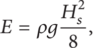
where E is the stored energy per unit wave surface (J/m2), ρ is the mass density of wave (1030 kg/m3), g is the acceleration of gravity (kg/m3), and H s is the progressive harmonic plan wave height (m). According to linear theory and superposition principle [20, 21], a real sea wave may be characterized as energy spectrum and the stored energy can be equally divided between kinetic energy and potential energy.
Assessment of wave energy resource is one of the important prerequisite work for wave energy extraction system designing and prototype testing. Actually, (1) is not enough for the assessment of wave energy resource. The assessment should include the characteristics of wave (e.g., wave height, wave period, water depth, and seasonal variation) and the location of wave energy extraction system (e.g., channel, reefs, harbor, and coast). In 1991, European Commission started a project to investigate the characteristics of wave energy and produced some recommendations for prototype testing [22]. The WERATLAS, funded by European Commission and considered as a reference for wave energy extraction system construction, proposed a proper numerical wind-wave modeling to describe the detailed characteristics of waves at 85 points off the Atlantic and Mediterranean coast of Europe [23].
Generally, the annual mean wave energy in offshore (20 ~ 100 kW/m in the areas of moderate-to-high latitudes) is much more than that in shoreline and near shore. Figure 1 shows the global distribution of annual mean wave energy density [24–27]. A large seasonal variation makes southern hemisphere (e.g., southern coasts of South America, western coasts of Europe, Africa, Australia, and New Zealand) a competitive candidate for the location of wave energy extraction station.

3. Offshore Wave Energy Extraction Technologies
The advantage of offshore wave energy extraction system lies in that a great deal of wave energy and economic benefits can be obtained through a high energy density in deep water [28, 29]. However, construction and maintenance of offshore wave energy extraction system are expensive and difficult due to the complex sea condition. The system may be subject to strong wave impulsive load (e.g., typhoon or hurricane) and thereby damaged by peak pressures. Since 95% of energy in offshore wave is between water surface and 7 m under water surface [28, 29], the objective of this section is to briefly review the technologies in offshore wave energy extraction system.
Offshore wave energy extraction systems are basically oscillating floating bodies, and the horizontal dimensions of these floating bodies are usually smaller than one wavelength. The idea of converting offshore wave energy into electrical energy has witnessed a significant development in recent years. Some important examples of offshore wave energy extraction systems are given below.
3.1. Single-Body Floating Systems
An early example of single-body floating system is a floating buoy connected to a linear permanent magnet generator of seabed-fixed device through a rope, and the rope is kept tight by a spring under the linear permanent magnet generator, as shown in Figure 2 [30–32]. Spring obtains wave energy during half a wave cycle (wave from trough to crest) and drives linear permanent magnet generator to produce electrical energy in another half of the wave cycle (wave from crest to trough). One advantage of this system is that the floating buoy's nature angular frequency in heave can be matched with the incident wave angular frequency. A full-scale single-body floating system (the radius of floating buoy is equal to 3 m) was constructed at a depth of 25 m, 2 km off the Swedish west coast, and tested in 2007 [30]. In the years to come, an array of single-body floating systems will be deployed at the same site to evaluate the concepts of technology, ecology, and economy.

The backward bent duct buoy, another single-body floating system (also known as an oscillating water column converter), was designed in Japan under the leadership of Yoshio Masuda. Figure 3 shows the sketch of a backward bent duct buoy [33]. In comparison with the frontward facing duct buoy, the advantages of backward bent duct buoy are that the oscillating water column could be designed to resonance with incident waves, and a high energy conversion rate with low mooring force could be achieved [34]. The backward bent duct buoy has been investigated in several countries (Japan, Korea, China, and so on) and installed in Japan and China. In the second half of 2006, a 12 m long prototype with a novel Walls turbine was installed off Ireland western coast [35].

Sketch of a backward bent duct buoy [33].
3.2. Two-Body Floating Systems
The single-body floating systems may cause some problems because of the unstable distance between water surface and seabed-fixed device, especially under the condition of typhoon or hurricane. In addition, installation of the device on seabed is expensive and difficult. Two-body floating systems may be utilized instead, where wave energy can be obtained through the relative motion between two floating bodies. The characteristics of oscillating of floating body are analyzed theoretically in papers [31, 32]. One famous example of two-body floating systems is PowerBuoy (shown in Figure 4) designed by Ocean Power Technologies Inc. (an American company in Pennington, NJ, USA), and installed off the Spain's northern coast with a capacity of 40 kW, in September 2008 [12]. The PowerBuoy consists of two floating bodies, the outer one acts as a resonating body with incident waves and the inner one as a fixed reference. The resultant mechanical stroking between two floating bodies drives a generator to produce electrical energy via a hydroelectric turbine, and the produced electrical energy is delivered ashore by an underwater cable.

Sketch of a PowerBuoy by Ocean Power Technologies Inc. [12].
Besides, PowerBuoy can be designed for strong wave impulsive load (e.g., typhoon or hurricane). PowerBuoy's sensors monitor the relative motion of two floating bodies and surrounding ocean waves continuously. In the case of strong wave impulsive load, the PowerBuoy will shut off and cease electrical energy production. The PowerBuoy will continue to produce electrical energy when the strong wave impulsive load has passed.
3.3. Multibody Floating Systems
The most successful wave energy extraction system based on multibody floating systems is Pelamis (shown in Figure 5), which represents one of the most widely-used offshore wave energy extraction systems with a high power capture/unit weight [13]. This system is a semisubmerged articulated structure consisting of several floating buoys linked through hinged joints. The relative vertical and horizontal motions of floating buoys are resisted by hinged joints which are used to drive electrical generators via high pressure oil and hydraulic motors. A set of three Pelamis has been installed at the European Marine Energy Centre of Orkney (a capacity of 750 kW) to establish the first grid-connected offshore wave energy extraction system for commercial purposes between 2004 and 2007. The Aegir wave farm of Shetland is expected to increase its capacity (10 MW) by installing 13 Pelamis [36, 37].

Sketch of the Pelamis [13].
4. Interaction between Wave and Floating Buoy
Study of the interaction between wave and floating body could benefit from previous investigations on the motion of ship in waves. This section will review the motion of floating buoy based on vertical wave force.
4.1. Added Mass and Damping of Floating Buoy
The hydrodynamic parameters such as added mass and damping play an important role in the study of motion of floating buoy, there exist a lot of numerical methods for calculating the two hydrodynamic parameters of floating buoy, for example, traditional wave source distribution method, finite element variation formulations, and integrovariational method [38]. However, the above numerical methods are time consuming and complicated. In fact, the two hydrodynamic parameters of floating buoy can be simply calculated by the use of eigenfunctions, especially for the low-frequency motion [39]. Therefore, a quick calculation method consists of parameters (e.g., water depth, radius of floating buoy, and its draft) and summary formulas for the two hydrodynamic parameters are proposed, and the calculation results are verified by some available experimental results [40].
It is expected that calculation of the two hydrodynamic parameters will optimize the dynamic performance of floating buoy design and increase the efficiency of offshore wave energy extraction system.
4.2. Vertical Wave Force on Floating Buoy
It is assumed that the dimensions of heaving buoy are smaller than incident wavelength, and the fluid is irrotational and incompressible and experiences variation in sinusoidal curve as time goes on. Then the linearized theory and potential energy theory are applied. Generally, the velocity potential of wave [43] can be expressed as

where
From potential theory the vertical wave force
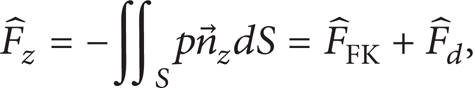
where p is hydrodynamic pressure,


Floating buoy with water plane area S
wp
, submerged volume V
p
(volume of displaced water), and wet surface
In (4) and (5), ρ = 1030 kg/m3 is the mass density of sea water, and ω is the angular frequency of sea wave. Equation (4) may be divided into one integral over the area S + S wp and one integral over the area S wp by area integral method [44], as shown in

In addition, the integral over the area S + S
wp
can be transformed into one triple integral over the displaced water volume V
p
by divergence

Therefore,

where
In order to calculate the diffraction force vector

4.3. Motion Equation of Floating Buoy
As shown in Figure 6, the floating buoy is subject to three forces, namely, the vertical wave force

where m
m
is the weight of floating buoy. According to linear theory, the radiation force

where

where m z and R z are added mass and damping of floating buoy, respectively.
Figure 7 (a) shows a two-body floating system oscillating in heave. The wave propagates in sinusoidal trace, at the wave height of 1.4 meters and wave period of 5 seconds. Both of the diameters of outer floating buoy and damper plate (at the bottom of inner floating buoy) are equal to 2.4 m. The function of damper plate is to increase the damping effect on inner floating buoy by the surrounding water. The depths of submergence of outer and inner floating buoys are shown in Figure 7 (a). From the above theory of interaction between wave and floating buoy, the speed curves of outer and inner floating buoys in heave are shown in Figure 7 (b). Based on this concept of relative motion between outer and inner floating buoys, a two-body floating system with a novel permanent magnet tubular linear generator rated at 5 kW will be installed off the eastern coast of China, in the second half of 2013.

(a) A two-body floating system and (b) speed curves of outer and inner floating buoy in heave.
5. Linear Generators
The ultimate product of wave energy extraction system is electrical energy, which is produced from various kinds of electrical generators (e.g., conventional rotating generators or linear generators) and delivered into a grid [45–49]. Electrical generator is one of most important devices determining the operation efficiency of wave energy extraction system. In the case of conventional rotating generators, a linear-to-rotary conversion device (e.g., air turbine, water turbine, or hydraulic motor) is needed to convert the linear motion of wave into a uniform rotary motion [50, 51]. Although the first linear generator has been proposed since over 100 years ago in the USA [52], and linear generators have been designed for wave energy extraction systems since the late 1970s [4], there are still very few kinds of linear generators that have been tested in sea waves. In recent years, the term “direct-drive wave energy extraction system” emerges, which indicates coupling the wave's speed and linear generator directly without any pneumatics or complex linear-to-rotary conversion systems. Thus, the complex conversion device is avoided and the mechanical loss is, therefore, decreased.
5.1. Two-Sided Permanent Magnet Linear Generator
Archimedes Wave Swing [41] is a fully submerged wave energy extraction system and consists of three parts: a two-sided permanent magnet linear generator, a basement (bottom part), and a floater (upper part), as shown in Figure 8. When a wave crest is above the AWS, the floater is pushed down by the added pressure of water, and when a wave trough is above it, the floater is moved up by the reduced pressure of water. The motion of floater is resisted by a two-sided permanent magnet linear generator, and the sketch of this two-sided permanent magnet linear generator is shown in Figure 9 [42]. There are several advantages of a two-sided permanent magnet linear generator:
high force density,
reasonable work efficiency,
permanent magnet material is cheap,
the electricity is only restricted in stator.

Sketch of the AWS [41].

Sketch of a section of the two-sided permanent magnet linear generator, where the arrows in permanent magnet represent the magnetization direction [42].
The AWS is the first wave energy extraction system, which is equipped with a permanent magnet linear generator, installed and tested in sea waves.
5.2. Permanent Magnet Tubular Linear Generator
A novel three-phase permanent magnet tubular linear generator (PMTLG) with Halbach array was proposed for wave energy extraction system by Southeast University, China, in 2010 [53]. One significant advantage of PMTLG is that assistant teeth are adopted to minimize the detent force and optimize the dynamic performance of wave energy extraction system. Figure 10 shows the structure of PMTLG. With the assistant teeth, up to 70% of detent force is reduced. A wave energy extraction system equipped with a PMTLG has been designed and tested in China under the supporting of National Natural Science Foundation of China (NSFC), as shown in Figure 11. The test results indicate that a large amount of wave energy (3–5 KW/m) can be obtained from the East China Sea and the South China Sea, which is quite considerable because China possesses a long coastline of over 18,000 km.

(a) Cross-sectional view of the PMTLG; and (b) prototype of the PMTLG.

A wave energy extraction system was installed in Xuanwu Lake, China (in trial phase).
Besides, a new linear switched reluctance generator was proposed for wave energy conversion by University of Beira Interior, Portugal, in 2012 [54]. The numerical analysis and optimization results showed that the proposed linear switched reluctance generator was high force density, robustness, and easy design and installation.
6. Discussions and Conclusions
Although many studies have analyzed offshore wave energy extraction systems theoretically and a few kinds of prototype have been tested in wave tank or real sea, some R&D financial supports from governments are still necessary for the construction and maintenance of the extraction system in harsh environment. In order to ensure a full-scale offshore wave energy extraction system absorbing wave energy maximally, the geometry and size of certain floating buoy should be designed to resonance with incident waves. For this reason, a larger size and capacity of linear generators are needed in design and construct (D&C).
Offshore wave energy extraction systems are still far from maturity. To develop a grid-connected and commercial offshore wave energy extraction system is not an easy task. Many difficulties and issues are still to be solved. Researchers in related fields should cooperate to promote technological development and avoid repetitive mistakes. It is believed that high quality research results would lead to a better working efficiency and economic benefit for the offshore wave energy extraction system.
This review shows the current status of offshore wave energy extraction technologies. The interaction between wave and floating body, as well as linear generators, is also illustrated.
Conflict of Interests
The authors declared that they have no conflict of interests to this paper.
Footnotes
Acknowledgments
This work was financially supported by the National Natural Science Foundation of China (Grant no. 41076054), Special Foundation for State Oceanic Administration of China (GHME2011GD02), and the Support of Science and Technology project from Jiangsu Provincial (BE2012138).