
Abstract
This study addresses the question of 3D path following for the observation class underwater remotely operated vehicle. The dynamic model of the investigated remote operated vehicle is taken as a coupled multibody system composing of a flexible body and a rigid body. For precise control, the tether cable disturbance has been investigated as well via a dynamic model. Each element of the tethered cable even has been taken as an elastic body, and the waves and current disturbances have been taken into consideration. Based on the multibody system model, an adaptive backstepping sliding mode controller has been designed. To improve the controller's systematic robustness against disturbances, the sliding mode surface and adaptive control rule have been designed, too. Experiments have been performed in a tank, including the 3D path following controls of depth, heading, advance, sideway, polygon line, and spiral line. With current and wave disturbances having been taken into consideration, the tether effect has been analyzed, the efficacy and superiority of adaptive backstepping sliding mode control have been verified. It is further confirmed from the comparisons that the investigated method outperforms those S surface based controllers.
1. Introduction
Observation class underwater remotely operated vehicles (ROVs) have been used widely in many areas such as hull and harbor inspection, underwater salvage, and pollution surveillance. High accuracy positioning and path following are demanded for underwater inspections and manipulations. The 3D path following is extremely important for accomplishing missions executed by subsea remotely operated vehicles. Observation class ROV is not so big; thus its motion is easy to be affected by the tethered cable, and also by current, wave, and wind. Therefore, the robust 3D path-following control for observation used ROV has been recognized as one of the most challenging issues [1, 2].
In order to meet the requirements of path following (sometimes refer to trajectory tracking when it is under a temporal law) for underwater vehicles, various types of control approaches have been studied. Kokegei et al. proposed a sliding mode controller for underwater vehicle to realize coupled 6 DoF trajectory control [3]. Bian et al. presented a nonlinear feedback controller based on input state for path following [4]. But those control techniques assume that the unknown dynamic model can be represented by a linear one with unknown parameters and a regression matrix is specified for the ROVs [5]. Fuzzy linguistic rules are more flexible for dealing with nonlinear control problems. Thus, Liu et al. in [6] and Wang et al. in [7] both provided an S surface (plane) controller in combination with fuzzy control for underwater vehicles navigation. A trained neural-fuzzy system can approximate the linear or nonlinear mapping of disturbance, but the objectives for training are usually difficult to be obtained; see in [8, 9]. Marzbanrad et al. modified sliding mode with robust adaptive fuzzy control algorithm for ROVs path following control. In that case, fuzzy algorithm was used for online estimation of external disturbances as well as unknown nonlinear terms of the dynamic model of the ROV. A robust control rule is employed to compensate the estimation errors [2]. Zhang et al. also derived an output feedback controller using nonlinear control theory [10]. They proved that a nonlinear output feedback integral controller provides exponential stability. In consideration of disturbance caused by wave-induced hydrodynamic forces, Patompak and Nilkhamhang provided an adaptive backstepping sliding mode controller for station keeping and path following of underwater vehicle based on its dynamic model [11]. Lapierre and Jouvencel extended a kinematic controller with backstepping and Lyapunov-based techniques so as to cope with parametric uncertainties and external disturbances [12]. The controllers shown in [13–15] confirmed that the model-based backstepping controller outperforms the conventional linear controller for the wide range of velocities.
A teleoperated ROV can be taken as a mass-spring system, and periodic waves accompanied with strong current may excite the motion of the vehicle. Tethered cable tensions may cause forces and position nonlinear oscillations on ROV as stated in [16, 17]. Thus a quasistatic or dynamic model reflecting the umbilical cable behavior is very necessary, however, being quite complicated, for precise trajectory control [18–20]. Prabhakar and Buckham developed a computational tethered cable model by applying finite element technique with decoupled PD controller [21]. Researchers de Souza and Maruyama estimated tethered cable dynamics from a lumped mass tethered cable model and issued a PI feed forward control strategy for ROV position control [22]. Soylu et al. considered the tethered cable as a series of lumped point masses connected by linear, massless, and visco-elastic springs and proposed a model-based sliding mode controller to improve the ROV performances [23]. Montano et al. modeled the tethered cable dynamics in a quasi-stationary state and presented adaptive control scheme for tethered cable perturbations [24]. Unfortunately, based on our knowledge, there are very few of previous studies that consider the effects from tethered cable and the disturbances from current, wave, and wind all together. However, none of these effects can be neglected during the practical applications. This study exactly focuses on this issue and contributes an adaptive backstepping sliding mode controller which takes into consideration all the mentioned aspects for the high precision 3D path following of one of observation class ROVs.
The rest of this study is organized as follows. Section 2 sets up the dynamic model of the ROV multibody system especially including the considered umbilical cable. A controller which is for the 3D path following is designed in Section 3, while Section 4 presents the experimental results. Conclusions are given in Section 5 to close this paper.
2. Dynamic Model of the ROV System
2.1. Modeling the Whole ROV Multibody System
The ROV is usually operating with the support vessel (mother ship) in the ocean; see Figure 1. The tethered cable not only provides power and communication media but also brings nonlinear drag forces upon ROV. In this study, the considered system is a multibody system including a flexible body, that is, the tethered cable, and a rigid body, that is, the ROV itself.
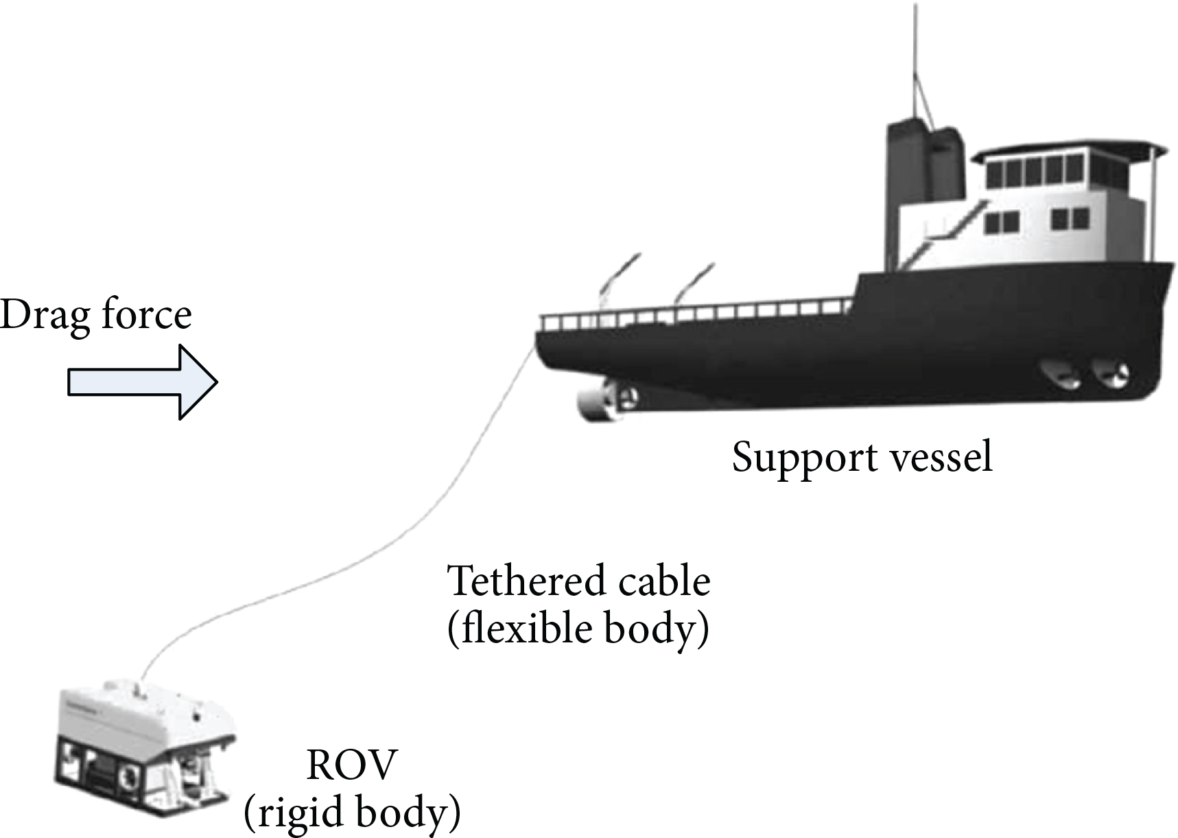
Multibody system of the considered ROV with tethered cable.
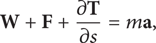
The dynamic equation of the whole ROV multibody system according to [5] can be represented by

where
2.2. Tethered Cable Drag Forces and Boundary Conditions
The tethered cable is a long flexible cylinder which can only sustain tensile loads and its length varies over the time. The tension force
where m is the effective mass per unit length,

then the tension force in (2) exerted at s with its value is calculated by

due to Hooke's law. In Figure 2, h1 is the diving depth of the ROV, and H0 and V0 are the horizontal and vertical drag forces, respectively, at the ship end of the tethered cable, that is, at point O c .

Model of tethered cable of ROV system in the water.
In order to analyze the motion of the tethered cable and its effect on the vehicle, three coordinate systems have been established which are the fixed frame [x, y, z], the local frame [ζ, η, ξ] on one of the cable ends at the mother ship side, and the ROV frame [i, j, k]. We define φ as the angle formed by the horizontal and local tangential direction at the considered point,

where
For the tethered cable in the air, the first item at the left side of (2) is W = Wair = Aρ
t
g in which g is the value of gravitational acceleration. Here only the vertical direction is considered since it is a gravitational force. If we set

as the wind effect on the dξ length tethered cable, where ρair is the air density, the strength of local wind velocity above the sea surface can be expressed by
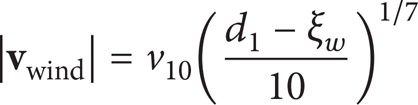
in which v10 is the wind speed at 10 meters above the sea surface, d1 is the cable height out of the water counting from O c to the water plane, and ξ w is only the cable height out of the water counting from the considered point to the water plane; see Figure 2. Here Cwind is the drag coefficient in the air. If we focus on the ith microunit length of tethered cable in the air; (see Figure 3), one has

Here we consider as usual that the wind is horizontal only, and in this case in right horizontal, T i and Ti + 1 are the two tension forces at the two ends of the ith microunit length cable, Wi, air = Aρ t g.

The ith microunit length of tethered cable in the air and its forces analysis.
Similarly, as shown in Figure 4, the tethered cable is in the water.
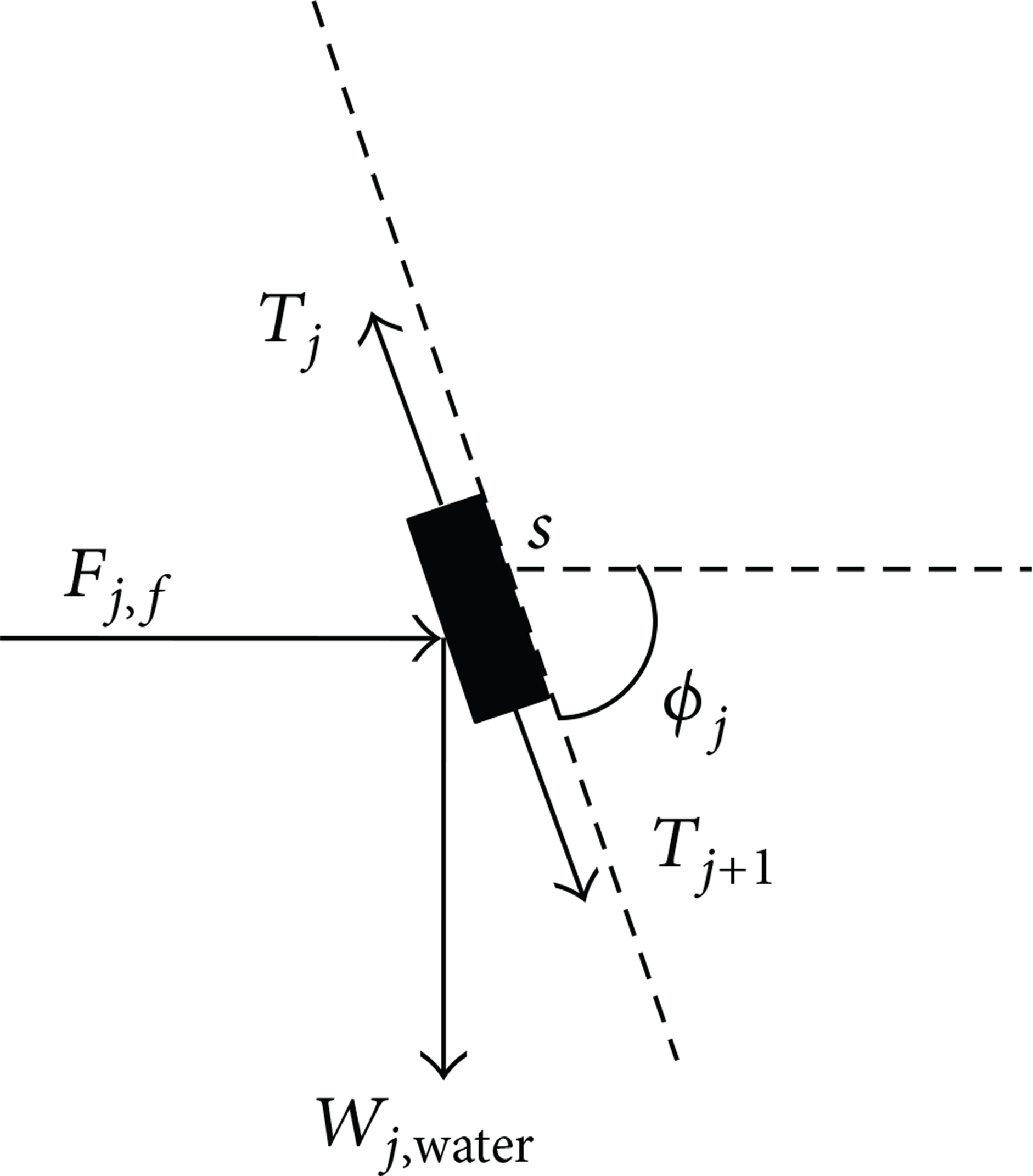
The jth microunit length of tethered cable in the water and its forces analysis.
Its dynamics in the water hold
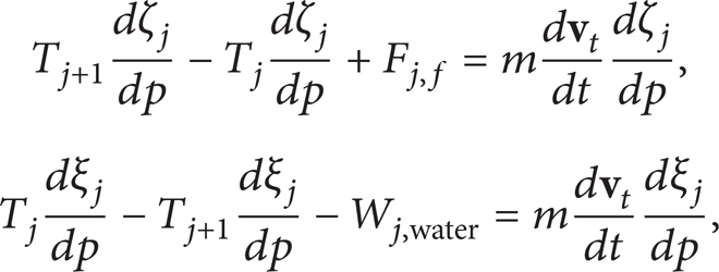
where Wj, water = (ρ
t
– ρ
w
)Ag, and ρ
w
is the density of water. Here T
j
and Tj + 1 are the two tension forces at the two ends of the jth microunit length cable under water, and F
j, f
is the force due to the wave and current disturbances which usually only considers for the horizontal direction. If

Thus, if the drag coefficient in the water is represented by C f , then

In this study we consider that the wave and current forces are in horizontal direction, for example, in Figures 2 and 4, and they are in the right horizontal direction.
Considering the boundary condition at s = 0, that is, at point O c , the cable tension force is

At the point R on ROV, the cable tension force can be calculated by

assuming that H
R
is in right horizontal direction and V
R
is in down vertical direction. Here
In (13), other corresponding terms can be governed by

where L s is the total length of the cable, that is, from O c to R, and L a is the length of the cable out of water, that is, from O c to the water surface.
In the following, we analyse the cable tension force at the water surface. This boundary condition can be considered either from the cable part in the air or the part in the water. Considering the cable in the air, one has

where Hsurair and Vsurair are the cable tension forces at horizontal and vertical directions, respectively. The actual directions of these cable tension forces are determined via the positive or negative characteristics of the force values. If it is positive, its actual direction is the same as assumed, otherwise in the opposite of the assumed. Here we assume that Hsurair is in right horizontal direction and Vsurair is in down vertical direction. In (15), W L a = AL a ρ t g. If we consider the cable part in the water, one further has

where Hsurwater and Vsurwater are the cable tension forces at horizontal and vertical directions, respectively, on the water surface and considered at the water side. In addition, the following equations should be met which are

The moment at R is governed by
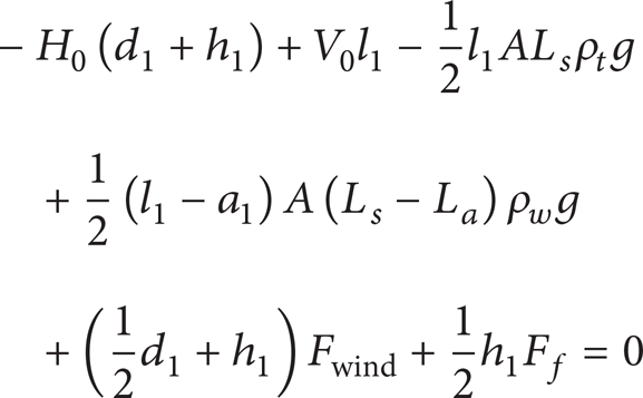
when it is in the equilibrium state. Here a1 is the horizontal length of the cable in the air, l1 is the horizontal length of the total cable.
3. Controller Design for Path Following
The ROV dynamic model described in state space can be expressed as

where
Step 1. According to the path following objective,

Then define virtual control coefficient

where k1 > 0. The velocity error of the ROV is defined as

The corresponding Lyapunov function is selected as

Thus,
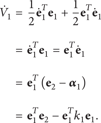
It is possible to adjust
Step 2. To improve the controller's systematic robustness against the disturbances, the following switching function of the terminal sliding mode surface is defined which is
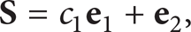
where
Therefore,

To satisfy the Lyapunov stability theory and the reaching law of the controller as in [25], the derivative

where h and β are positive constants. We design the back-stepping sliding mode controller as

where
Step 3. In order to estimate further disturbances Δ

where γ is a positive constant. If we assume the disturbance Δ

The adaptive control rule can be selected as
Further we can design the backstepping sliding mode controller as same as in (29); that is,

With (31)–(33), one can obtain

If we set

it yields

By selecting proper values of h, c
i
, and k
i
to satisfy

where
4. Experiments
4.1. Experimental Setup
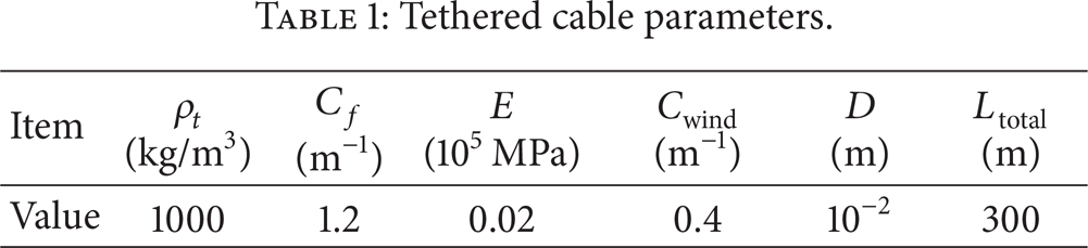
In order to verify and analysis the investigated tethered cable dynamic model and the backstepping controller, experiments have been performed based on an SY-II remote operated vehicle; see Figure 5. The SY-II ROV is an open frame underwater vehicle, which is purposed for ship hull inspection. Its power supply and communication cable are a neutrally buoyant tether which is attached to the vehicle at the tail. The control commands are sent through network communication between surface computer and PC104 embedded processor. It is equipped with depth gauge, ultrasonic Doppler velocity meter (DVL), magnetic compass as motion sensors, underwater CCD, image sonar, ultrasonic thickness gauge as environmental sensors, and 6 thrusters including 2 main thrusters, 2 side thrusters, and 2 vertical thrusters. Its tethered cable and hydrodynamic and inertial parameters are illustrated in Tables 1, 2, and 3, respectively. The experiments have been performed in a 50 m × 30 m × 10 m tank at the Key Laboratory of Science and Technology on Underwater Vehicle in Harbin Engineering University. Comparisons have been made between the S surface controller investigated in [6] and our adaptive backstepping sliding mode controller. Current and waves are generated from local current generation device (Figure 6 (a)) and multidirectional waves generator (Figure 6 (b)), respectively, in the experiments to simulate real oceanic conditions.
Tethered cable parameters.
SY-II hydrodynamic parameters.

SY-II inertial parameters.


SY-II open-frame underwater vehicle.
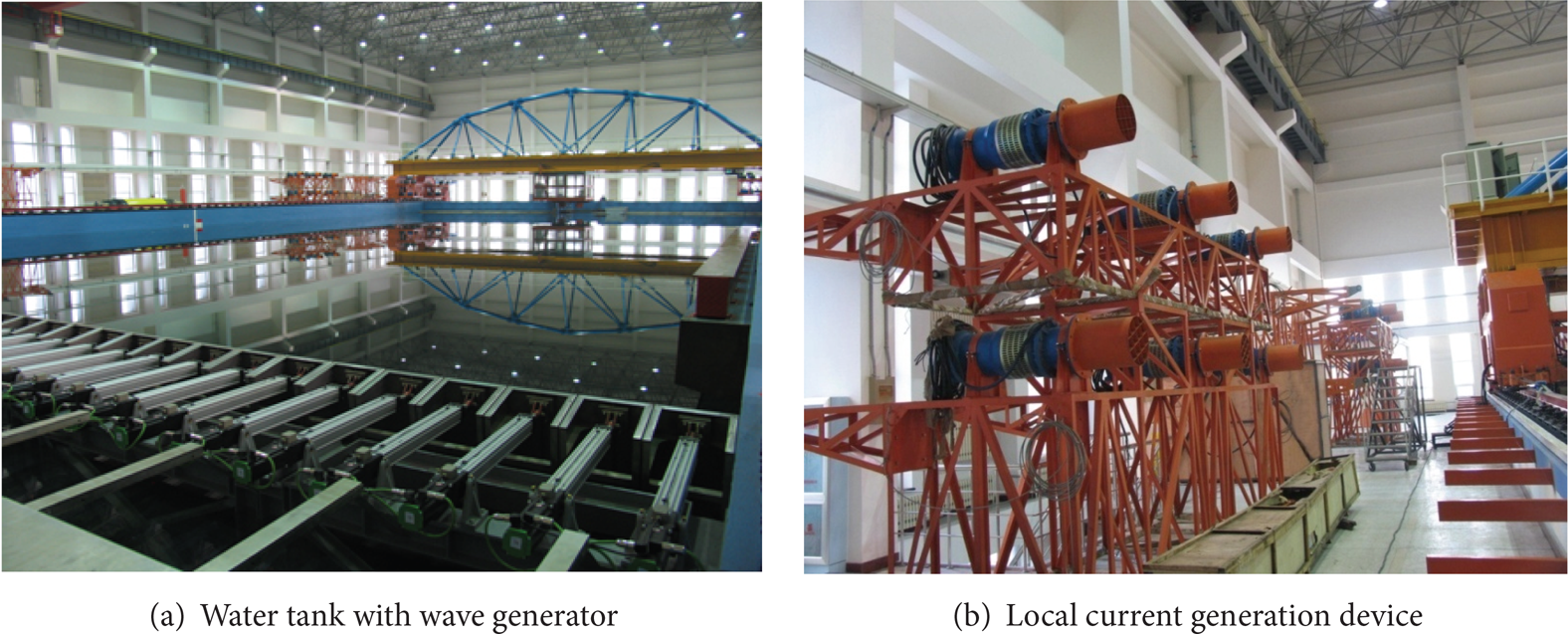
Water tank with wave generator and local current generation device.
4.2. Experiments and Results Analysis
In the depth control experiments of Figures 7 and 8, the tension force from tethered cable upon SY-II ROV changes little mainly because its neutral buoyancy, and the peak values of tethered cable moment are decided by diving speed. The tethered cable makes little effect upon depth control when diving is not very fast. Adaptive backstepping sliding mode controller has improved the stability and speed constringency in depth control in comparing with S surface controller since it provides dynamic compensation during the experiments.

The 6-meter depth control experiments.
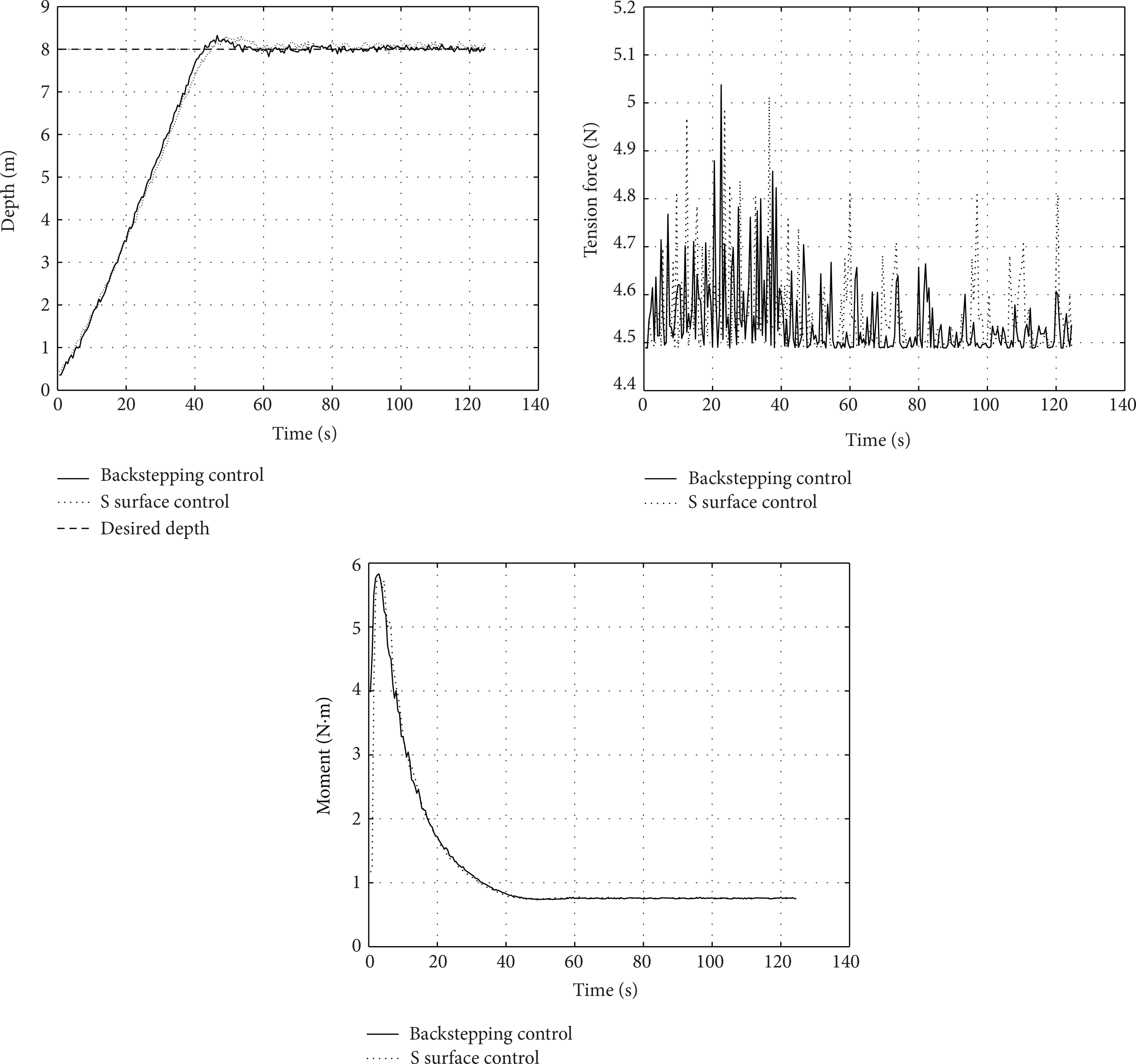
The 8-meter depth control experiments.
In the heading control experiments of Figures 9 and 10, the desired heading is 40° and – 30° relative to the normal north of earth's magnetic field. The tension force and moment from tethered cable upon SY-II ROV change a lot at first during revolution process. The tethered cable and ROV's rectangle shape have made nonlinear effects to the ROV manipulation. As a result, the S surface controller cannot realize precise heading control, while adaptive backstepping sliding mode controller qualifies, since the controller delivers command according to its dynamic manipulation and character.

The – 30° heading control experiments.

The 40° heading control experiments.
During the northward advancing process (see Figures 11 and 12), the SY-II ROV that is advancing mainly depends on two main thrusters. Two conditions, that is, Vcurr = 0 and Vcurr = 0.4 m/s normal east (Vcurr is the currents speed), are compared. Here the current has made great influence upon tethered cable and generates tension force and moment. Nonlinear disturbance from current and tether has produced much greater errors for the S surface controller than the adaptive backstepping sliding mode controller.

Advance toward north with two main thrusters, Vcurr = 0.
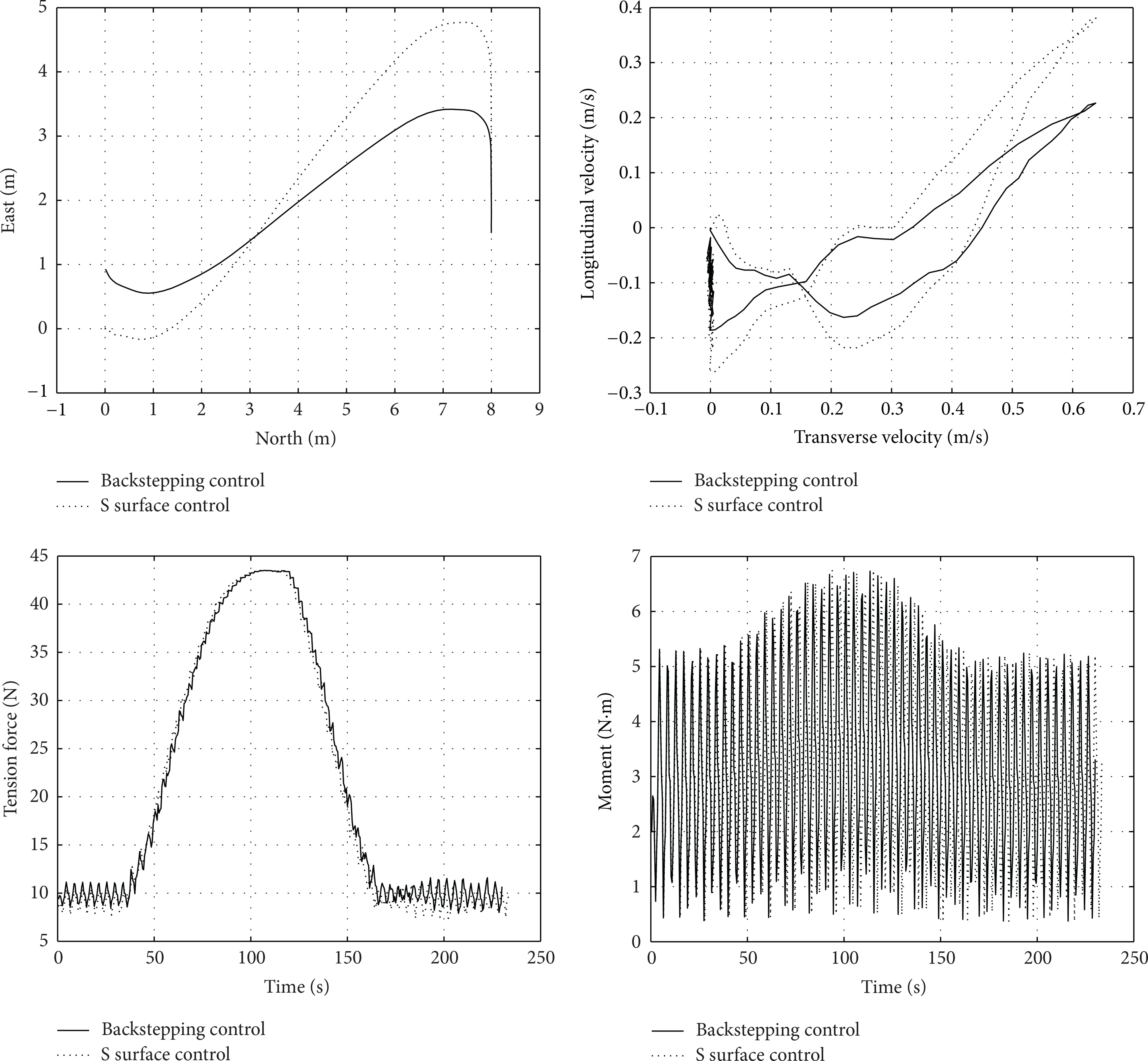
Advance toward north with two main thrusters, Vcurr = 0.4 m/s normal eastward.
During the eastward lateral motion process (see Figures 13 and 14), the SY-II ROV that is laterally moving mainly depends on two lateral thrusters. Two conditions, that is, Vcurr = 0 and Vcurr = 0.4 m/s normal north, are compared. At first SY-II ROV has been blown a few meters away, and then the control started. The current has generated great tension force and moment effect upon SY-II ROV. Adaptive backstepping sliding mode controller has realized more accuracy result compared to the S surface controller.
Lateral motion toward east with two side thrusters, Vcurr = 0.

Lateral motion toward east with two side thrusters, Vcurr = 0.4 m/s normal northward.
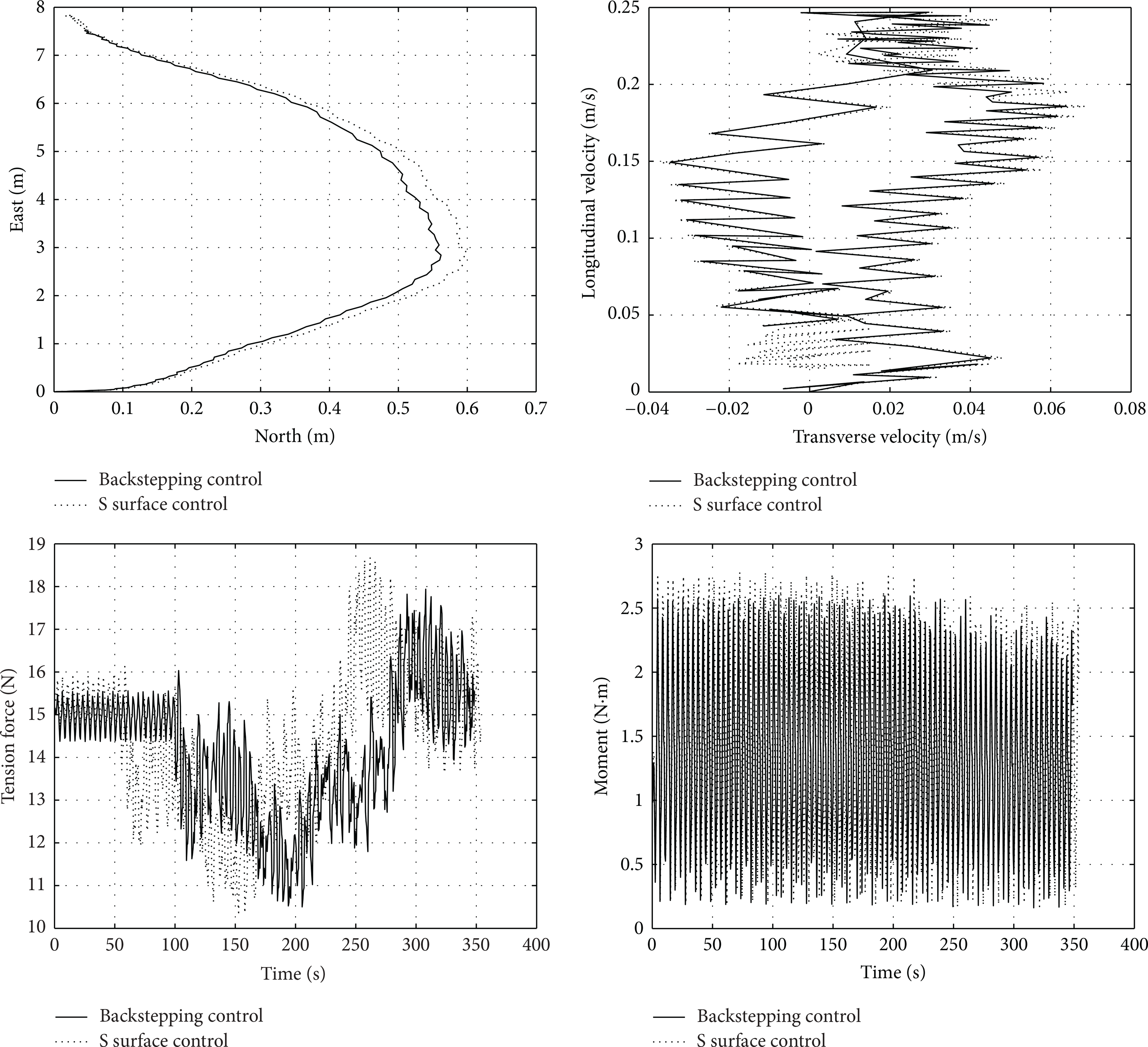
During the 3D path-following experiments in the tank (see Figures 15 and 16), the disturbances are current and waves. The current speed is Vcurr = 0.4 m/s, the wave is a sine wave with speed Vwave = 0.2 m/s, and height Hwave = 0.2 m, respectively. Polygon path and spiral path are followed, respectively. As the experiments we made above, environmental disturbances exerted on the tethered cable have contributed nonlinear effect to the ROV. The S surface controller manages to follow the polygon path but have to adjust continuously and heavily to follow the spiral path. Comparatively, adaptive backstepping sliding mode controller can compensate more disturbances and can follow the desired path more precisely. Deduced from dynamic model, adaptive backstepping sliding mode controller is established to calculate and compensate nonlinear disturbances caused by current and tether. Therefore, it outperforms S surface controller in control accuracy and robustness.

3D path-following experiments, polygon path, Vcurr = 0.2 m/s, Vwave = 0.2 m/s normal northward.

3D path-following experiments, spiral path, Vcurr = 0.2 m/s, Vwave = 0.2 m/s, normal northward.
For the experiments to be performed successfully, we have also run some preliminary simulations to get the initial value of some uncertainties. The simulation and experimental results agree with each other well. Details of simulation results can be found in [26, 27].
5. Conclusions
The main contributions of this paper are summarized as follows. At first, the dynamic tether model has been established based on the lumped mass cable model. Each element of the cable is taken as an elastic body and takes into consideration waves and current disturbances. Based on the dynamic model, an adaptive backstepping sliding mode controller has been designed. Secondly, the controller has taken dynamic model into consideration at the first and second steps (backstepping steps) based on Lyapunov functions. To improve the controller's systematic robustness and against disturbances, the sliding mode surface has been defined. An adaptive control rule has been chosen to further resist environmental disturbance which is the most difficult part for ROV 3D path following.
Experiments have been performed in the tank, including depth control, heading control, advance control, sideway control, polygon line, and spiral line 3D path-following control. With current and waves disturbances being taken into consideration, tethered cable effect has been analyzed, and the efficacy and superiority of our designed controller have been verified. The comparisons to the S surface controller have shown better performances of the investigated adaptive backstepping sliding mode controller.
Conflict of Interests
The authors declare that there is no conflict of interests regarding the publication of this paper.
Footnotes
Acknowledgments
This project is supported by National Science Foundation of China under the Grants of no. 51209050, no. 51179035, no. 51279221, and no. 61100006, the Doctoral Fund of Ministry of Education for Young Scholar with no. 20122304120003, State Key Laboratory of Ocean Engineering of Shanghai Jiao Tong University no. 1102, State Key Laboratory of Robotics and Systems of Harbin Institute of Technology no. SKLRS-2012-ZD-03, and the Fundamental Research Funds for the Central Universities with no. HEUCFR1101.