
Abstract
Modular robot are said to construct a diversity of morphogenesis with self-assembling strategies. They bring about an adaptive entity to deal with complex tasks. By analyzing integration design in module, perception, and control in detail, a swarm modular robot is presented with self-assembly scenario. Then, these active docking robots use the distance measured by infrared sensors between itself and edge of assembled structural entity as input. We design the fuzzy sets and if-then rules according to the human reasoning in following process. Based on Mamdani-type inference, the fuzzy controller can yield two outputs. The outputs are, respectively, used as steering angle speed and linear speed. Due to the diversity of self-assembled structure by the swarm modular robots, we conduct a series of simulated experiments. The results demonstrate the effectiveness and efficiency of the proposed controller in swarm robots' edge-following process.
1. Introduction
Modular robots have been viewed as a new approach to rapidly manufacturing kinds of structural objects and some symbiotic robotic configuration using autonomous development methodologies [1–3]. In this subarea recently attracting the robotic communities, self-assembling of a swarm of robots is widely developed as an efficient mechanism enabling shaping what is desired [4–6]. In spite of physical or intelligent limitation (such as size, computing, power, and manipulation) of independent incapable robots in certain circumstances, the swarm robots can use self-assembly method to form inter-robot physical connection to generate a stronger robotic entity.
A swarm of modular robots in a self-assembly system generally is homogeneous, and some rich resources including hardware and software are embedded in each one by mechatronics. Compared with traditional fix-structure robots, the self-assembly system incorporating modularity offers significant flexibility and economic advantage by changing the connectivity between different robotic modules or parts. In some extreme conditions such as extravehicular activity (EVA) on orbiting spacecraft or planetary surface, these modular systems can be employed at any time to assemble into manipulators or coexplorer space robotics to replace or assist the crew. One scenario can be envisioned that, before the crews reach Mars, a large number of robots have assembled into Mars houses including furniture [7].
According to the functional or geometric characteristics, there is a large body of research works, respectively, focused on different types of modular robotics. Distributed swarm robots are equipped with the appropriate grasping or connecting mechanisms to assemble into physically coupled morphologies [8–12]. These robots use low-level control logic to determine the connection sequences and distributed controller to connect with the base or beacon. With group-level cooperation, the connected swarm robots can make collective responses, for example, cooperative transportation or moving on rough terrain. Each robot is self-mobile and capable to interact with others, but the resulting entity is incapable to stand up and be extended in 3D space.
Without considering the engineering limitation, one subarea of morphogenetic robotics [13] focuses on the cognitive development, which concentrates the codesign of the controller and morphogenesis [14]. Based on lattice-type self-reconfigurable robots, a few evolutionary or bioinspired algorithms are employed to generate artificial structures or biological lifeforms [15, 16]. From potential engineering viewpoint, collective constructions combine the passive blocks and active mobile robots [17]. Inspired by social insects, the mobile ground robots [18, 19], aerial vehicles [20, 21], or external propulsion/fabrication device [2, 22, 23] can collect the modular passive blocks to construct complex structure which usually is stationary and however not given the capacity of whole body's locomotion.
Combining the advantages of the robots mentioned above, swarm modular robots in distributed mode are able to disassemble or assemble into different morphogenesis which either are functional structures or locomotive organisms [24–26]. These swarm modular robots often move on the ground and can self-assemble into 2D planar organism, and afterward, can reconfigure into 3D structure. These self-mobile and interactive robots are more flexible to construct the composite entity without external direction or assist. However, the design of the higher degree of modularity integrating components and embedded system is required as well as adaptive algorithms [27]. In our previous works, a swarm modular robot is proposed. These independent robots self-assemble into different configurations, and self-assembly based on finite state machine [28] and whole body locomotion [29] are verified. Different from our previous work, in this paper, we focus on self-assembling process of one single robot. Considering successful development of fuzzy control on robot navigation and following [30–33], a many-input many-output (MIMO) fuzzy control method is introduced to enhance self-assembling function according to an analysis of the robot navigation in stage of seeking the assembled entity's open docking direction. The proposed method improves the efficiency of self-assembling.
This paper is organized as follows. In Section 2, we describe the swarm modular robot system including structure, perception, and function and give some illustration of their constructing entity. In Section 3, the experiments and general control method based on finite state machine (FSM) are presented. In Section 4, we introduce the fuzzy controller in self-assembling process in detail. This controller allows the active robot can follow the partially or fully assembled entity. In Section 5, we implement the experiments where a robot followed a diversity of morphologies steadily. Finally, we conclude and discuss future work.
2. Swarm Modular Robot
The swarm modular robot with self-assembly function is designed to satisfy the capabilities of autonomous morphogenesis from a number of elementary components. It is featured that each modular robot to operate and move as a single self-contained individual with the capacity of self-propulsion, perception, computation, and power supply. The second significant capacity of the modular robot is to aggregate into different morphogenesis and disaggregate any time through docking elements and information sharing. Besides, evolution capacity incorporating sensing, computing, and responding in a changing environment is a key issue for autonomous morphogenesis.
2.1. Robot Module
This study was conducted on the groups of swarm modular robotic system, which consists of a number of self-propelled modular robots called Sambot (see Figure 1). The Sambot robot synthesizes characteristics of swarm robots and self-reconfigurable robots. Each Sambot is a wheeled mobile robot which is composed of a cubic main body and an active docking interface. There is a pair of docking hooks on active docking interface whilst there is a pair of docking grooves on each of four lateral interfaces. On the two wheels on the bottom of the main body, the robot can use the active docking interface to grasp any passive docking interface on four laterals of the other robot's main body. Thereby, a swarm of Sambots can autonomously move and self-assemble into certain kinds of morphological structures by physical connections with each other. When two robots are connected, the active one can rotate the other through rotating joint.
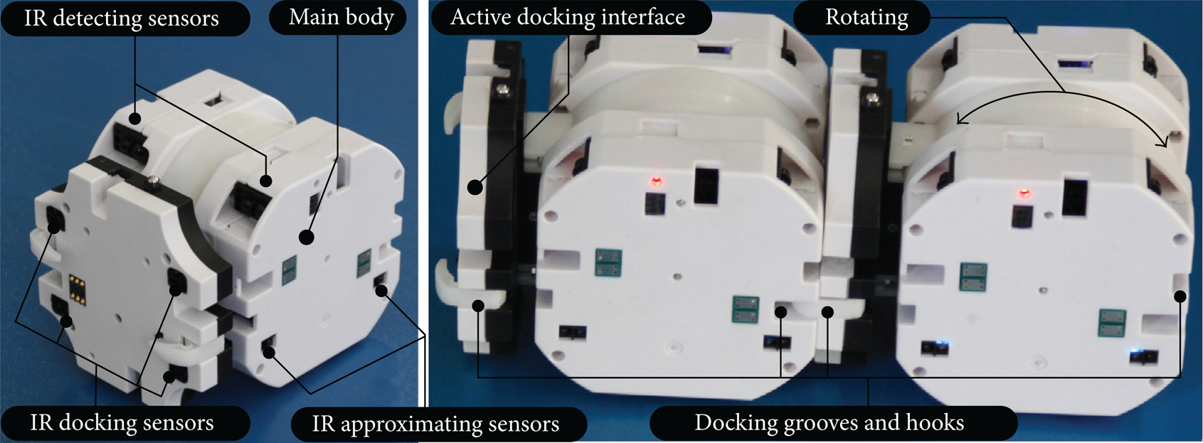
Swarm modular robot (Sambot). Size: 102 mm length, 80 mm width, 80 mm height; weight: 350 g, including: battery (2 hours), ZigBee communication, and MCU.
2.2. Perception
Each robot is surrounded by a group of infra-red (IR) sensors. Each pair of sensors consists of an emitter and a receiver, shown in Figure 1. They are divided into three classes according to their functionalities.
IR detecting sensors. These sensors are installed on the upside of the front of the main body, and they can measure the remote range and detect certain height of objects and other robots, as shown in Figure 1.
IR approximating sensors. On each lateral side of the main body, there are two pairs of sensors to measure the distance between the robot and others, as shown in Figure 2(a).
IR docking sensors. Four pairs of sensors are mounted on the active docking interface for docking alignment or work as “IR approximating sensors” in self-assembly stage, as shown in Figure 2(b).

(a) Measuring the distance by emitting signals and receiving them reflected from another object. (b) Receiving the signals from other robots' emitters.
On one hand, these IR sensors could measure the distance by emitting signals and receiving them reflected from another object. On the other hand, they can receive the signals from other robots' emitters in order to align the active docking interface and the passive one.
2.3. Inter-Robot Freedom and Their Morphogenesis
From degree of freedom view point, the modular robot features four degrees of freedom (dof). Each robot can move on the two differential derived wheels, having three degrees of freedom on the plane (see Figure 3(a)). An additional dof is introduced to allow the active docking interface rotating around the main body (see Figure 3(a)). According to docking direction of the two connected robots, two connected robots can fix the in between dof, including two robots' rotation axes orientation parallel (see Figure 3(b)) or orthogonal (see Figure 3(c)).

Actuation generating degree of freedom and orientation of the rotation axes. (a) Rotation axes orientation. (b) Parallel axes. (c) Orthogonal axes.
Simultaneous connection to a robot is available, and thereby these modular robots can construct different configurations of organisms (see Figure 4) through rearrange of degree of freedom. These morphogeneses are brought about according to high-level command or adaptive self-assembly.

Diverse morphogenesis including the locomotive organism and manipulating tool.
2.4. Software Architecture
For achieving distributed control and modularity in software as well as hardware [34, 35], the different layers of software development are shown in Figure 5. On the bottom, some basic modular functional components such as sensors, direct servo, and MCU are standardized to open to the upper layer. Middleware is on one way used to define the unified interfaces, on the other way to maintain local communication with close or vicinal robots using CAN bus when connected or Zigbee when disconnected. A large number of perception or motion libraries are integrated into the MCU, and some energy and fault management tasks are predesigned to load when they are necessary. Each robot has two states. When swarm robots work without connection, they use distributed controller including behavior-based or target-oriented subcontroller to make a collective response to the environments or high-level command. When they are assembled, they are either commanded by the center or make decision by distributed controller.

Software architecture embedded in robotic system. The programs in each robot are identical and distributed to adapt to the task requirements.
3. Experiment Scenario and Self-Assembly Strategy
A swarm of robots is distributed inside the platform, a table surrounded by a fence. They search for the partially assembled entity or a robot who recruits the surrounding robots. In our previous work [28], a self-assembly method based on the finite state machine is proposed to grow the structure. The process of self-assembly has three main stages: wandering, following, and docking (including locking).
First, one robot, called SEED, broadcasts signals over the air to attract other robots and simultaneously opens its IR sensors on the docking interface as “docking” directions. Then, other separate robots begin to wander for searching for the docking directions. In wandering stage, as shown in Figure 6, the robot search for assembled entity using the combination of IR detecting sensors and IR approximating sensors. If it meets the fence before finding assembled entity (see ① to ② in Figure 6), it would follow along the fence (see ② to ③ in Figure 6) until the corner and switch to approximate the assembled entity along the diagonal of this corner (see ③ to ④ in Figure 6); if otherwise, it would detect the assembled entity and directly switch to following stage. Then, the active robot will follow the edges of assembled entity until it captures the docking directions using its IR approximating sensors installed on the left side (see ④ to ⑤ in Figure 6). When one of IR signals representing docking direction is detected by the robot, the robot would align itself with the passive docking interface on the assembled entity and dock with it (see ⑤ in Figure 6). After that, the active docking robot becomes a part of the assembled entity and opens IR sensors to be docked by others according to the topology. In previous work, a method incorporating connection state table and tree-like graph is proposed to conduct self-assembly. Once a robot docks with the assembled entity, it can lookup connection state table and determine its position in graph to get connection state in order to decide which sensors to open.
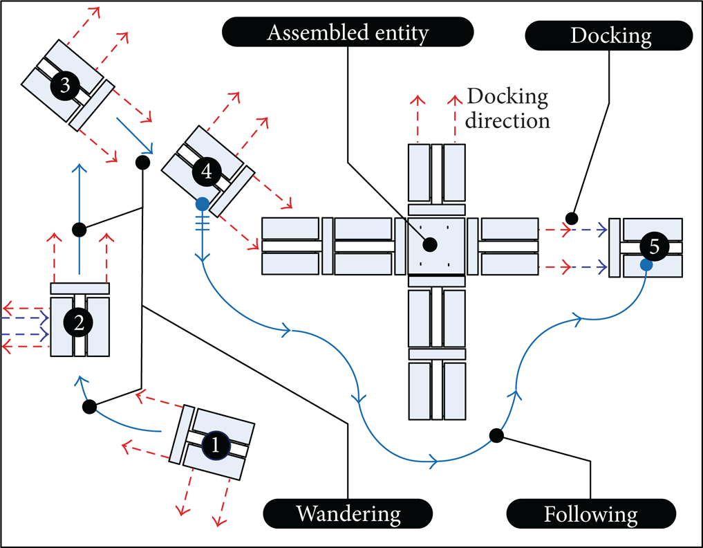
Self-assembly process based on finite state machine in the sided experimental arena.
Considering the improvement of the self-assembly algorithm, we analyze the three stages. Efficiency of wandering stage depends on the experimental arena, and docking stage costs less time than other two stages. Thereby, we focus on the following stage and use fuzzy control to conduct edge-following. Through edge-following, the individual robot can navigate smoothly along the edges of the assembled entity for seeking docking directions.
4. Fuzzy Controller for Edge-Following in Self-Assembling
Due to the diversity of morphology which can be assembled by a swarm of robots, the shapes of the edge are changing. The fuzzy controller based on Mamdani model is designed to guide the robot to follow the edges of the assembled entity.
4.1. Inputs, Outputs, and Fuzzification
Infrared sensors measure the distance between the lateral side of the robot and the opposite edge of the assembled structure. As shown in Figure 2(a), the left front, left back, front left, and front right distances are, respectively measured and represented by the linguistic variables dLF, dLB, dFL, and dFR as input variables of the fuzzy controller. Each input variable is divided into five fuzzy sets: hard near (HN), little near (LN), zero (ZE), little far (LF), and hard far (HF).
The outputs of fuzzy control are linguistic variables υ and ω, respectively, representing the moving linear speed and steering speed of the mobile docking robot. υ is described by five fuzzy sets: hard slow (HS), little slow (LS), run normal (RN), little fast (LF), and hard fast (HF), and ω is described by three fuzzy sets: hard left (HL), little left (LL), run center (RC), little right (LR), hard right (HR).
Thereby, the belongingness of each input or output to a particular fuzzy set is determined via the trapezoidal membership function (MF) as follows:

According to the measuring distance by IR sensors and movement capacity of the robot and safety margin, the universe of discourse of the fuzzy set of inputs dLF, dLB, dFL, and dFR is [20 80] mm. Considering the maximum speed, the universe of discourse of the fuzzy set of outputs υ and ω is, respectively, [0 100] mm/s and [−100 100] degree/s. The fuzzy controller is described in Table 1, and membership functions of input and output are illustrated in Figure 7.
Fuzzy controller including the input and output.


Input and output fuzzy sets and the corresponding, membership functions. (a) Input: dLF, dLB, dFL, and dFR. The distance respectively, measured by the front left, front right, left front and left back sensors are located five sectors which partially overlap. The obtained four input variables have the same distribution function in discourse domain. (b) Output: υ. Five overlapping sectors describe the intensity of the linear speed from stop to maximum. (c) Output: ω. To avoid head-on or lateral collision to an edge, the steering orientation is divided into left and right.
4.2. Fuzzy Rule Base
In the edge-following process, the rule base for both wall following and obstacle avoidance is constructed based on the human reasoning. The following three metarules are employed to design fuzzy rule base.
If the robot moves forward at an appropriate distance from edge of assembled entity without any other structure in the front, the robot steers straight.
If the robot deflects to the left, heading against the assembled entity, or deflects to the right, going away, then the robot would turn towards the opposite direction to correct a deviation.
If there exit parts of assembled in the front of the robot, the robot would turn right to align the left side of the robot with the front edge.
Here, we divide the fuzzy rule base into two subbases, one of which is used to achieve edge-following and the other for avoidance and alignment. According to the above metarules, we use dLF, dLB, dFL, and dFR as inputs and, respectively, yield υ (see Tables 2(a) and 3(a)) and ω (see Tables 2(b) and 3(b)) as outputs. In edge-following stage, we assume these exist no parts of the assembled entity at the front of the robot (dFL is HF and dFR is HF) and only use the dLF and dLB as variables, as shown in Table 2. Regarding the avoidance and alignment stage, without consideration of dLF and dLB, only dFL and dFR are adopted, as shown in Table 3.
Fuzzy rules for edge-following using dLF, dLB, dFL and dFR as input and yielding υ and ω as outputs. In the process, dFL, and dFR measured by the two front sensors are large, indicating no objects in the front of the robot.
Fuzzy rules for obstacle avoidance using dFL and dFR as input and yielding υ and ω as outputs. In the process, dLF and dLB measured by the two left sensors are not taken into consideration.
4.3. Fuzzy Inference and Defuzzification
We use a Mamdani-type fuzzy inference to formulate the mapping from the sensed distance to control action. Based on fuzzy rules mentioned above, the outputs of each rule are combined into a single fuzzy set, and we use the center of area (COA) defuzzification method to resolve two output values, respectively obtaining robot linear speed υ and the steering angle ω.
5. Experimental Simulation and Discussion
According to the morphology of assembled entity, we design a number of structures to verify the fuzzy controller. In the following process (mentioned in Section 3), the active robot would follow the edge of partially assembled entity to seek the docking direction which might occur anywhere and towards any possible direction. In this section, considering the fulfillment of structural shapes in different situations, we conduct the simulation in MATLAB to make the robot follow the whole edges.
According to a diversity of morphogenesis mentioned in Section 2, we use the swarm modular robot to assemble some structural configurations on planar surface, and an active robot is placed at a distance from the assembled entity. In Figure 8, the assembled structures consisting of a large number of identical robots are simplified in black. The active robot will follow the edges by detecting the black pixels. These structures mimic some shapes of animals. In Figures 8(a) and 8(b), a snake-like structure composed of nine robots and one composed of thirteen robots are connected in black block representing the modular robot, the active robot followed the boundary smoothly. In Figures 8(c) and 8(f), there are two short sections of concave boundary. In Figures 8(d) and 8(e), two long sections of concave boundary lead the active robot into it, and the active robot still can escape from the conflict and succeed in following.

Morphogenesis consisting of a number of robots and trajectory when the active docking robot follows the edges. These structures can be assembled in 2D surface and followed. (a) Snake-like configuration. (b) Octopus-like configuration. (c) Little quadruped configuration. (d) Large quadruped configuration. (e) Lizard-like configuration. (f) Human-like configuration.
Table 4 lists the number of the robots constituting the black entity and shows the time of the robot's following whole edges. Regarding these facts that influence efficiency of following, number of concave corners cause the robot to take more time to adjust itself. In the previous work [28], when it is expected to dock with snake-like and quadruped structure of five robots, it took up to 100 s to follow the edges to search for the docking direction based on state-based behavior method. Obviously, fuzzy controller in this study is an improvement.
Records of the edge-following process shown in Figure 8. These factors provide evidence for analysis of controllers.

6. Conclusions
The distributed swarm modular robot can move itself to explore which robots claimed for docking. Through a self-assembling method, groups of these robots can aggregate into certain structures beyond the individual limitation in body and brain. In this study, we in detail present the capacity of swarm modular robots including the hardware, perception, and software, which can address elements of autonomous construction. A fuzzy controller is applied in the self-assembly process for seeking the docking direction. For a large number of structural entities, we implemented the controller and analyzed the efficiency. It is obvious to shorten the time to follow the edges of the assembled entity.
In the future, we will implement distributed control in swarm robots and self-assembled structure and build an online response strategies using self-assembly to enhance adaption to the environments. Considering respective advantages of the evolutionary computing and fuzzy control, we expect to further improve fuzzy controller on the inefficient or ineffective aspects in the self-assembly process.
Footnotes
Acknowledgments
This work is supported by the National High Technology Research and Development Program of China (“863” Program) (2012AA041402), National Natural Science Foundation of China (Grant nos. 61175079 and 51105012), and Fundamental Research Funds for the Central Universities (Grant no. YWF-11-02-215).