
Abstract
We propose a system for improving gas safety management through the use of wireless communication modules and intelligent gas safety appliances. Our system configuration consists of an automatic extinguishing system, detectors, a wall-pad, and a microcomputer controlled micom gas meter to monitor gas flow and pressure as well as the occurrence of earthquakes. The automatic fire-extinguishing system checks for both combustible gaseous leaks and monitors the environmental temperature, while the detector array measures smoke and CO gas concentrations. Depending on detected conditions, the micom gas meter cuts off an inner valve and generates a warning, the automatic fire-extinguishing system cuts off an external valve and sprays extinguishing materials, or the sensors generate signals and take further action when smoke or CO is detected. Information on intelligent measures taken by the gas safety appliances and sensors is transmitted to the wall-pad, which in turn relays this as real time data to a server that can be monitored via an external network (BcN) connection to a web or mobile application for the management of gas safety. To validate this smart-home gas management system, we field-tested its suitability for use in Korean apartments under several scenarios.
1. Introduction
To ensure occupant comfort and safety, modern, high-end houses and apartments built in Korea are increasingly being equipped with sensor-based devices to monitor and regulate gas, electricity, and water facilities [1], a trend that will surely continue to produce improved monitoring systems. The evolution of ubiquitous wireless sensor networks (USNs) has fostered the development of “smart environments” in which numerous sensor nodes are embedded in streets, houses, buildings, and automobiles [2]. One component of the smart environment—the automatic meter reader (AMR)—is designed to deliver total monthly usage data, but it can also gather detailed usage information, automatically detect leaks and equipment problems, and aid in tamper detection [3]. Several gas safety management systems incorporating intelligent multifunction gas meters based on ZigBee network technology, automatic gas leak cutoffs, and smoke, methane, and temperature detectors have been proposed by the authors [4], who, in conjunction with other researchers, also pioneered in the development of the micom gas meter—an intelligent microcomputer controlled gas meter—with a built-in cutoff valve and sensors for detecting flow, pressure, and seismic events. If the micom gas meter detects an abnormal state with respect to any of these factors, it uses an inner valve to shut off gas flow and then delivers a user warning [5]. In addition, an external gas valve can be cut off if the monitored temperature surpasses 100°C or if a gas (methane or CO) leakage or fire is detected at either the gas pipeline or the facilities. The safety management systems developed in these studies have been fabricated using CC2430 and EM250 ZigBee chips with ZigBee Pro stacks [6, 7].
In this study, we designed a new gas safety management system (GSMS) based on a JN5139 ZigBee wireless networking solution and tested it under various scenarios. Our system is an automatic fire-extinguishing system (AFES) with a star topology centered on a micom gas meter and a smoke and CO detector [8]. The AFES serves as a router to deliver safety and risk signals to a wall pad that functions as a ZigBee network gateway [9], and if an abnormal state occurs at each sensor node, the system takes preventative safety measures and then informs safety managers and users that a risk situation has occurred. The embedding ability of this system into the “internet of things” and its connectivity to smart device networks in homes and other buildings were demonstrated through field testing.
2. Development of Wireless ZigBee Communication Modules
Figure 1 shows a ZigBee module based on Jennic's JN5139 wireless microcontroller. These modules are used in our system both as wall pad sink nodes and as sensor nodes for the micom gas meters, automatic fire-extinguishing system— which serves as a router— and the smoke and CO detector.

ZigBee module with JN5139 microcontroller.
The monitoring devices use JN5139 microcontrollers that are both ZigBee and standard IEEE802.15.4 2.4 GHz compatible [10], with 16 MHz, 32-bit RISC CPUs, and 96 and 192 kB of RAM and ROM, respectively, along with four-input 12-bit analog-to-digital converters (ADCs), two 11-bit digital-to-analog convertors (DACs), two comparators, a temperature sensor, two universal asynchronous receiver transmitters (UARTs), and two-wire serial interfaces.
3. Wireless Modularization of Gas Safety Apparatuses
3.1. Intelligent Micom Gas Meters
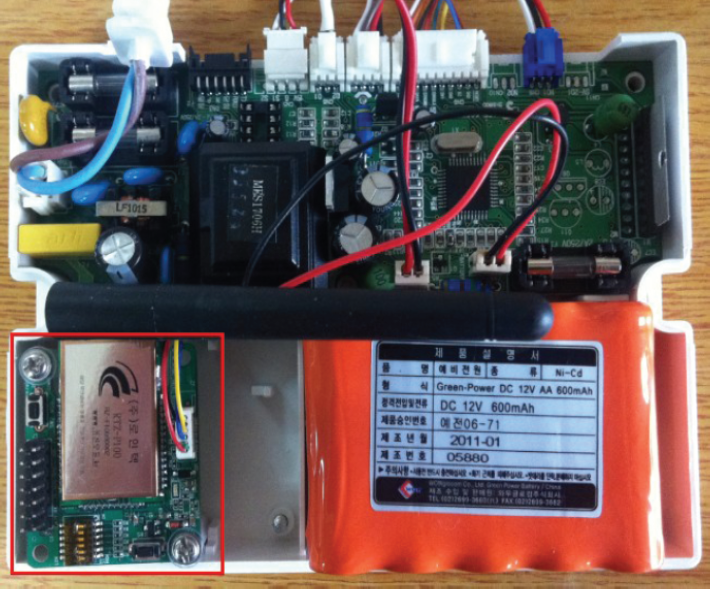
The intelligent micom gas meter—a variant of a standard gas meter with a built-in microcontroller and a cutoff valve—not only measures gas flow and pressure but also can monitor earthquake activity. The meter can open and close an inner cutoff valve and deliver a warning to users if abnormal measurements of gas or seismic activity occur in a gas facility or house. Figure 2 explains the components and functions of an intelligent micom gas meter incorporating a wireless ZigBee communication module (cyan color) with a JN5139 microcontroller. The meter classifies flow measurements as massive, cumulative, instantaneously rising or descending, while pressure measurements can be high or low. The earthquake function with associated alarm buzzer is triggered by an event of magnitude 3.0 or higher on the Richter scale. Two of the micom gas meter external ports are connected to additional gas detectors and sensors that deliver signals for gauging gas safety states in specific sectors. Table 1 shows the safety functions of the micom gas meter, including automatic control and shut-off.
Functions of an intelligent micom gas meter.


Components and functions of micom gas meter with ZigBee module.
3.2. Automatic Fire-Extinguishing Systems (AFES)
Figure 3 shows an automatic fire-extinguishing system (AFES) controller with a ZigBee module, and Figure 4 shows the AFES in its connected configuration for detecting gas leaks and abnormal temperatures. In the event that a risk signal is received from a gas leak detector or if the temperature sensor indicates temperatures above 100°C, the AFES controller closes a shut-off valve; if the temperature reaches 130°C, the controller induces the fire-extinguishing system to spray suppressing chemicals when the temperature goes up over 130°C for at least one minute. To detect combustible gas, the detector system outputs at 12 V.
Interior of AFES controller with ZigBee module.
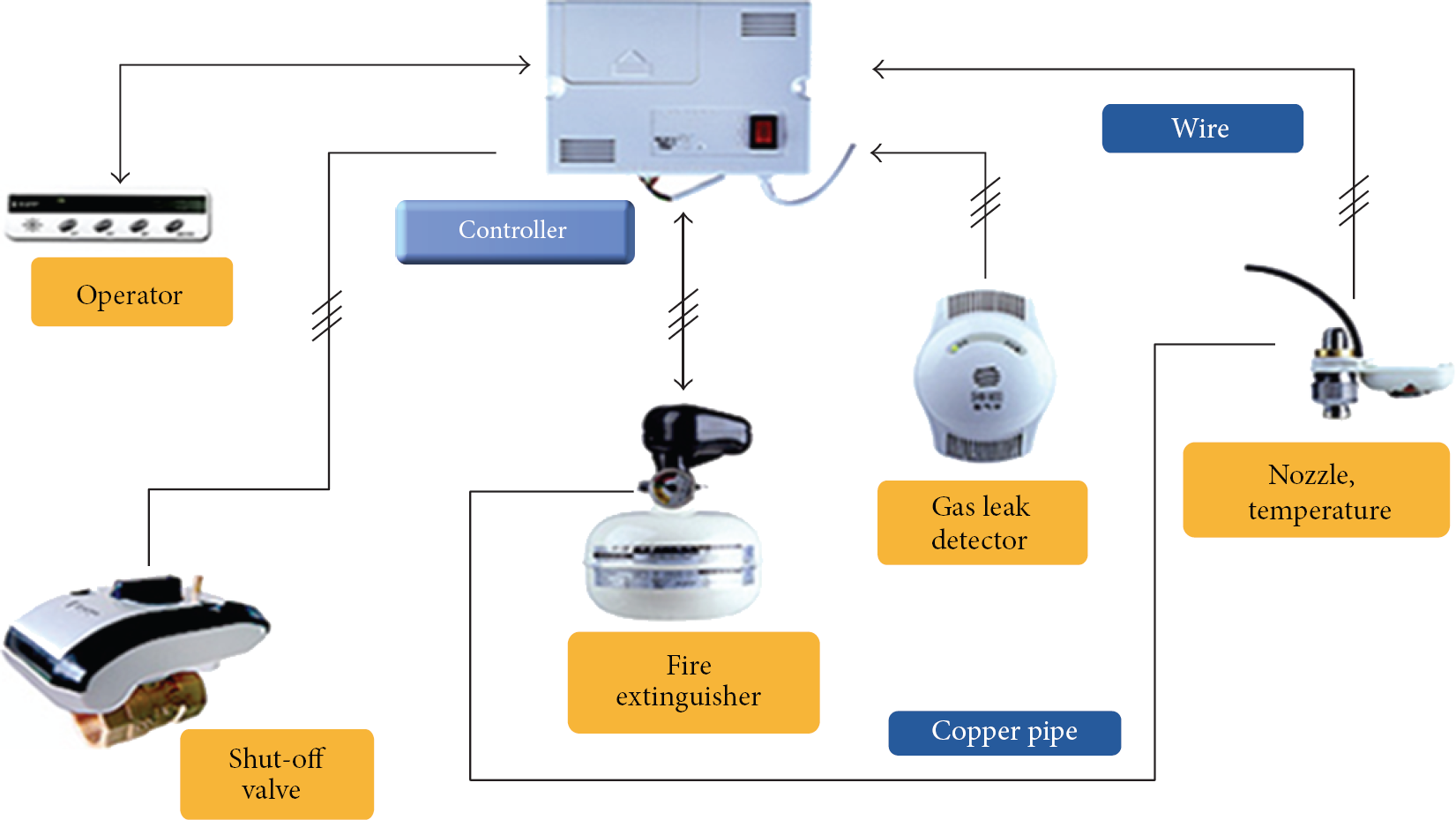
Diagram of connected AFES configuration.
3.3. Smoke and CO Detectors
Figure 5 shows a smoke and carbon monoxide (CO) detector with a wireless ZigBee module; when a fire occurs, the detector sends an event signal to a wall pad via the automatic fire-extinguishing system receiver. The CO monitoring functionality is useful in gas boilers, where incomplete combustion of fuel produces toxic carbon monoxide; if CO gas is detected, the CO sensor sends a risk signal to the wall pad via the automatic fire-extinguishing system receiver, while smoke levels are monitored to determine if a fire is occurring.

CO and smoke detector with ZigBee module.
3.4. Wireless Wall Pads with ZigBee Modules
Figure 6 shows the front and rear sides of a wall pad equipped with a wireless ZigBee communication module. The wall pad contained is controlled by an embedded Windows XP Pro operating system, features an 8.4 in LCD panel and an Atom N270 1.6 GHz CPU, and has 1 GB of DDR2 RAM, a SATA 160 GB hard disk drive (HDD), and USB-type wireless Ethernet LAN connectivity. In order to test the wall pad application program, we implemented several gas safety management scenarios (see Table 3) using Microsoft Visual Studio 2010. In the simulations, the wall pad received gas flow, pipeline pressure, and earthquake-related data through a micom gas meter, and gas leaks or temperatures in the range of 100 to 130°C were signaled by an automatic fire-extinguishing system consisting of a smoke sensor and CO detector. If an abnormal state occurred in all gas safety appliances, the wall pad took emergency action and then delivered the relevant signals and state data to the web via a mobile server. Figure 7 shows an assembled gas safety system consisting of appliances and wall pad controllers; using this, we conducted a pilot experiment in which the gas safety appliances and wall pad controller were subjected to various scenario conditions.
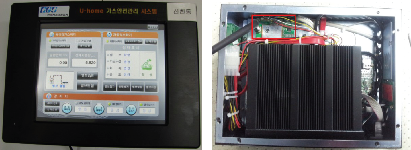
Front and rear sides of a wall pad with ZigBee module.

Experimental pilot setup consisting of gas safety appliances and wall pad.
4. Smart-Home Gas Safety Management System (S-GSMS)
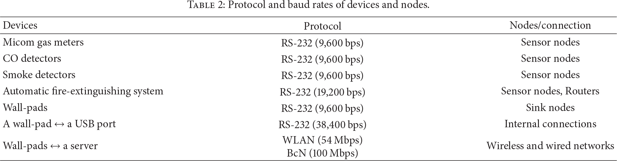
Table 2 shows the communication protocols and baud rates of the devices used to affect gas safety management system interconnection, and Figure 8 shows both wired (solid lines) and wireless (dotted lines) signal flow in the system. The wireless sensor network is configured by classifying the sensor nodes as, variously, micom gas meters, automatic fire-extinguishing system, smoke and CO detectors, or sink nodes (e.g., wall pads), and inner protocols are interfaced between the nodes and appliances. The diagram shows the signaling stream directions used to manage the system through a website; in this case, a smart phone network controls the gas safety appliances via internet and mobile connectivity. Through the internet gateway, the smart phone application sends ZigBee commands to the management system, which in turn relays these commands the JenNet (JN5139) wireless network. A wireless microcontroller on each network gas safety appliance runs an application to interpret the ZigBee commands in order to control the appliance and monitor the gas safety state. Users can connect to a gas safety management server through either the web or a mobile site at any time or place in order to inspect and manage system operation. As described previously, an internal valve within the micom gas meter will close if it receives abnormal information from the gas flow, pipeline pressure, or earthquake sensors, while the automatic fire-extinguishing system will close an external valve if it receives a gas leak reading or detects temperatures above 100°C. If smoke and CO are detected together, both the gas meter internal valve and the external valve are closed.
Protocol and baud rates of devices and nodes.
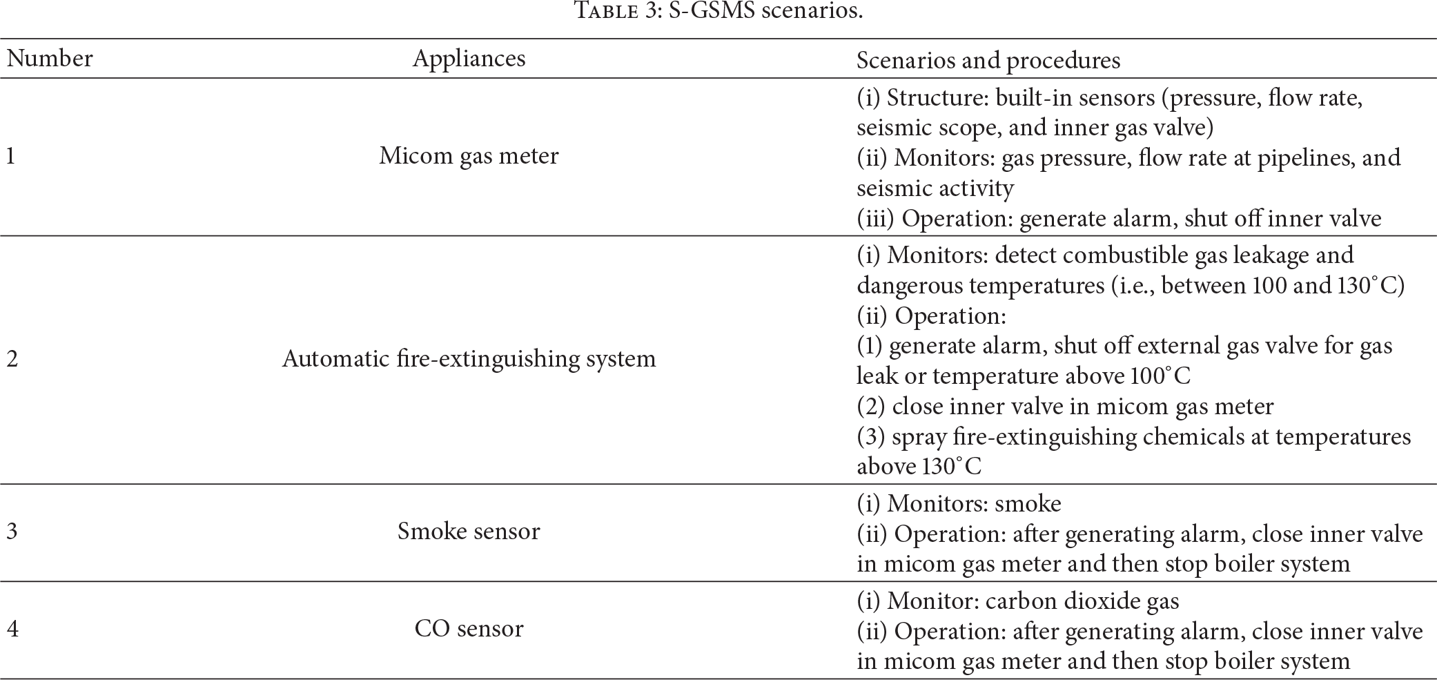
S-GSMS scenarios.

Network configuration of the gas safety management system.
Following the configuration shown in Figure 9, we installed a smart-home gas safety management system (S-GSMS) in an apartment building with the server located in the apartment management office. Based on data provided by the gas safety devices, this system is able to independently implement the security steps described above and then notify users, safety managers, gas suppliers, and governing bodies via the management server in the event of gas leakage or abnormalities in terms of pressure, flow, or seismic conditions. Table 3 lists the test scenarios and procedures for gas safety management used by the devices, and Figure 9 shows a schematic diagram of the safety appliances, wall pad, routing technology, and wireless web server— an ML350G6 HP server with a Xeon E5504 processor that configures the web and mobile sites using MS SQL 2008MS hosted on a Windows 7 operating system.
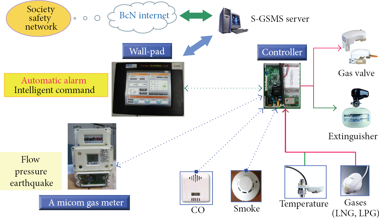
Smart-home gas safety management system (S-GSMS) signal flow.
5. Experimental Results
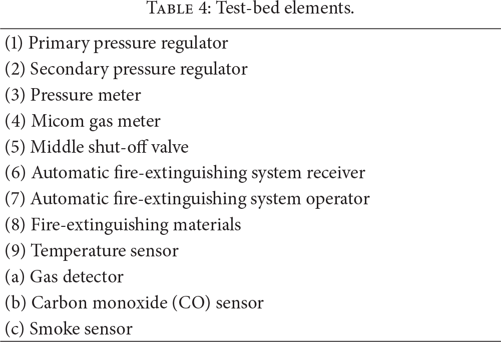
We manufactured a test-bed shown in Figure 10 to assess the performance of the S-GSMS when subjected to the scenarios shown in Table 3. Table 4 lists part names in Figure 10. Before field testing and application of this setup, we carried out enough experiments using air instead of gas in which the air pressure was lowered using primary and secondary pressure regulators by two orders of magnitude to about 2.8 kPa, which is approximately the pressure in a working gas pipeline. The items and parameters tested included wireless communication operation, control of the wall pad, pressure levels, gas use response, seismic measurements, gas leakage, temperature, and levels of smoke and CO detected.
Test-bed elements.

Test-bed for experimentally assessing S-GSMS.
Figure 11 shows a control flowchart of remote, web-based management of the S-GSMS. As shown in the figure, the micom gas meter decides whether the inner valve needs to be shut and then closes or opens the valve based on measured consumption flow, gas pressure, usage time, or detection of an earthquake of magnitude 5.0 or greater on the Richter scale. The automatic fire-extinguishing system, which serves as a router, opens and closes the external valve in the event of a temperature measurement above 100°C or a detected gas leak, while sensors detect smoke and carbon monoxide; Figure 12 shows the experimentally detected CO concentration data. The wall pad delivers all information received from the fire-extinguishing system router to the server. Based on the test results, which are discussed below, the system delivered outstanding normal processing performance when assessed against the scenarios described in Table 3.
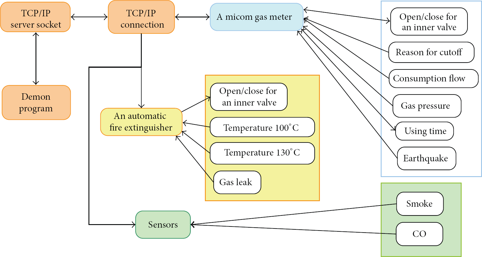
Flow chart diagram of S-GSMS accessed via websites.
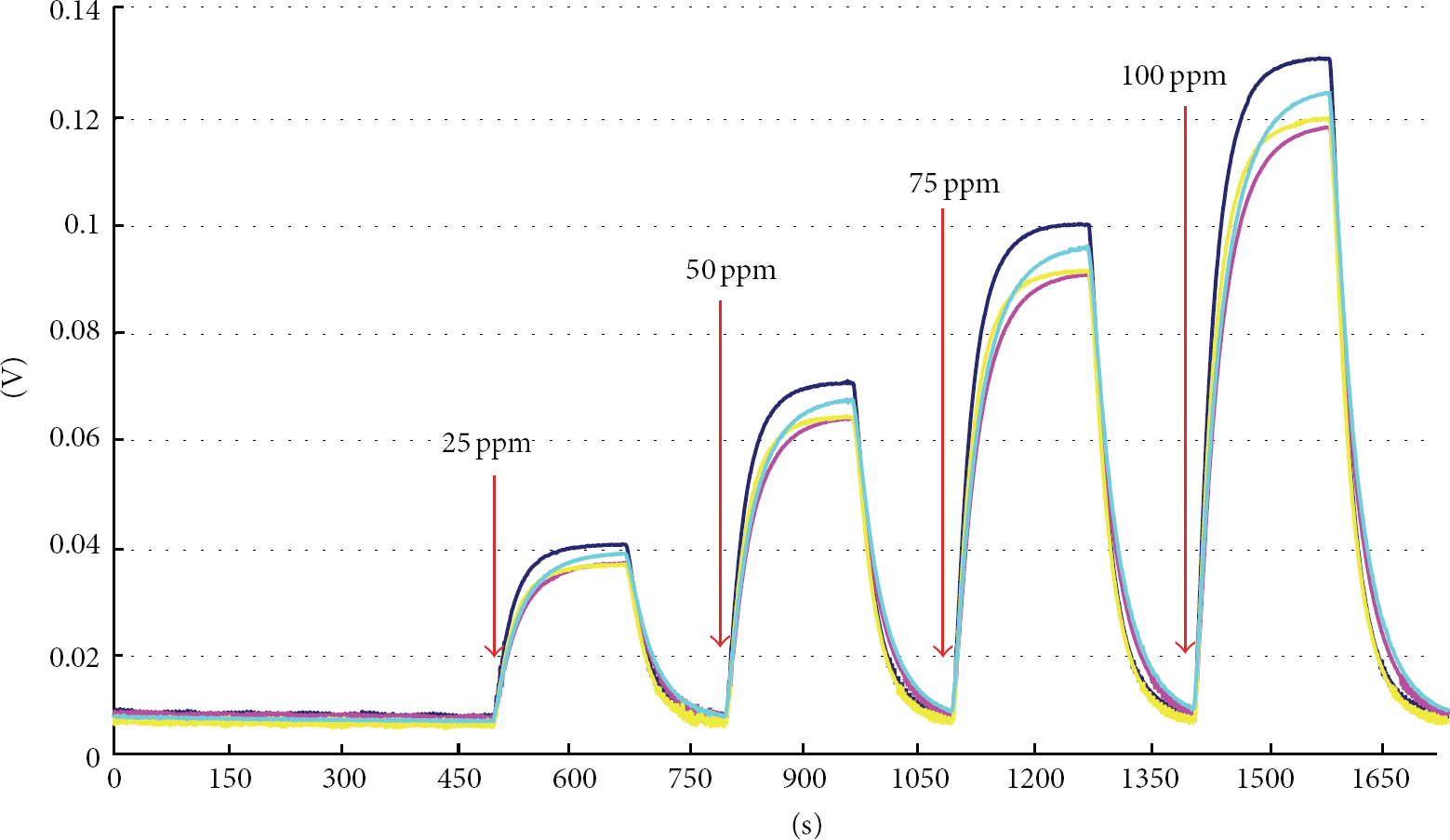
Experimental CO concentration data.
Figure 13 shows a schematic of the gas safety appliance system control and management procedure implemented in a living room and monitored on a smart phone screen through a connected mobile site. In this experimental setup, we installed realistic gas safety appliances, a wall pad, and a server with web and mobile pages and verified that the controlled function outputs on the smart phone (Galaxy Note 1, Samsung Co., Ltd.) coincided with those on the PC (HP Co., Ltd.). Figure 14 shows a relational flow diagram model for processing the S-GSMS data in order to manage the gas safety and risk history, and Figure 15 shows a test setup in which we used several S-GSMSs to control and manage more than 100 houses in four villages. Using this setup, a test run of the system with respect to the gas safety scenarios listed in Table 3 was conducted.

Field test in a living room to verify S-GSMS operation.

Relational model for processing S-GSMS data.

Performance test of multiple S-GSMSs.
Table 5 shows the experimentally assessed response times for each S-GSMS sequence, while Table 6 explains the various sequences. Figure 16 shows data gathered in daily measurements by the micom gas meter of (1) cumulative flow rates and (2) instantaneous rising flow rates. If the cumulative flow rates exceeded a predetermined target value, the inner valve of the meter was closed. The inner valve was also closed in the event of gas pipeline cracking or overheating, as these events would cause an abrupt increase in the instantaneous flow rate. Figure 17 shows experimentally measured gas pipeline higher and lower pressure vales than the default values respectively by the micom gas meter. If daily measuring pressure of the inner micom gas meter broke bounds predetermined high or low pressure values a by fire or leakage, the inner valve of the meter was closed.
Response times for S-GSMS safety measures.

S-GSMS safety measure sequences.

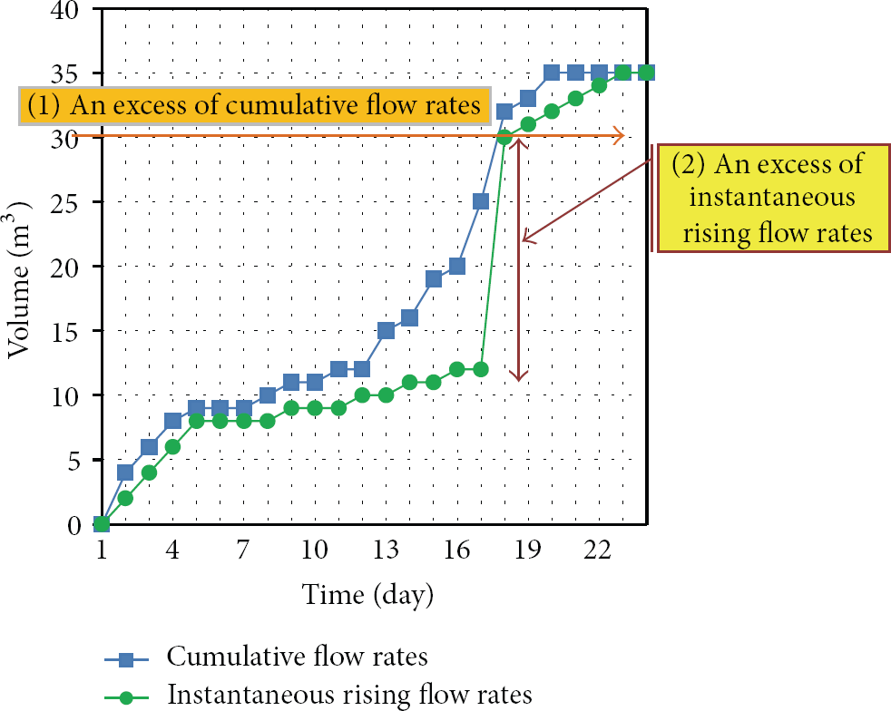
Experimentally measured gas flow rates.

Experimentally measured gas pipeline pressure.
6. Conclusion
In this study, we developed and tested a smart-home gas safety management system (S-GSMS) for use in Korean houses based on a network of gas safety appliances equipped with wireless ZigBee communication modules incorporating JN5139 controller chips. We designed an S-GSMS consisting of gas safety appliances, sink nodes (e.g., wall pads), an automatic fire-extinguishing system, and smoke and CO sensors and tested it against various gas safety management scenarios. To implement this system, we designed and manufactured wall pad sink nodes programmed to affect gas safety management scenarios in order to control the safety appliances. Using this system design, we configured a ZigBee-based wireless sensor network for use in a house. To perform gas safety management, the sensor network was connected to an external network (BcN), which, in turn, was connected to both the internet and a smart phone network. Based on data on gas flow rate, pipeline pressure, detected seismic activity or gas leakage, temperature, and CO and smoke concentration, our proposed system can be used to take a variety of safety measures if an abnormal state occurs and then inform users and safety managers of the situation via smart phone messaging. Using simulation and experiment, we demonstrated that our S-GSMS can successfully prevent abrupt gas-based incidents in order to minimize damage to gas facilities or buildings.
Based on the results discussed here, the proposed system can be effectively integrated into wireless and wired integrated communication networks in order to prevent dangerous gas and fire incidents.