
Abstract
An innovative auxetic-cored sandwich panel (AXP) is proposed. Its perforation resistant performance under high-velocity projectile impact was numerically analyzed using the validated finite element simulation techniques and compared with that of the aluminum foam-cored sandwich panel (AFP) of identical dimensions and weight. It has been found that the AXP is far superior to the AFP in ballistic resistance because of the material concentration at the impacted area due to the negative Poisson's ratio (NPR) effect. A parametric study was carried out to investigate the effects of several key parameters, including impact velocity, face and core thicknesses, and core density, on the ballistic resistance of the AXP and AFP. The results show that the ballistic limit and perforation energy of the AXP is greatly affected by these parameters. Meanwhile, the advantages of AXP over AFP being used as ballistic resistant structures are highlighted. The primary outcome of this research is new information on the development and design of advanced ballistic resistant structures containing auxetic materials.
1. Introduction
Sandwich panels with metallic cellular material fillers have been widely acknowledged for their excellent energy absorption capability in addition to their light weight. Therefore, they have been employed as energy absorbers in a wide range of applications involving extreme loading conditions such as ballistic impacts. Most of the existing efforts on the ballistic impact of sandwich structures with conventional honeycomb cores have focused on the out-of-plane scenarios when the projectile moves along the axis of the honeycomb core [1, 2], as depicted in Figure 1. The effects of several parameters on the energy dissipation of sandwich panel during axial perforation were experimentally tested by Goldsmith and Sackman [3], including the impact velocity, the boundary condition, and the bonding strength between the honeycomb core and the aluminum faces. Meanwhile, analytical and numerical solutions have been obtained for the ballistic limits of honeycomb sandwich panels subjected to normal projectile impacts [4, 5]. It was observed that folding of the cell walls and shearing of the plug play the major role in energy dissipation and ballistic resistance of the aluminum honeycomb panels against projectiles [6]. It was also found that the energy absorption capability of the honeycomb is very low, and its cell size, wall thickness, and core thickness have little effects on the penetration resistance of the sandwich panel [7].

Axial impact on honeycomb structure [2].
For the above reasons, current investigations into the ballistic resistance of metallic cellular cored sandwich panels have been more focused on the panels with aluminum foam cores, as the aluminum foam can absorb a large amount of energy under high-velocity impacts [8]. It was found that the composite armors with aluminum foam cores perform better than the ones without foam cores under ballistic loadings [9–11]. The effects of several key parameters on the ballistic limit and perforation energy of the aluminum foam-cored sandwich panels (AFPs) have been analyzed through experiments [12, 13]. All these works have shown that the AFP has a good performance in the ballistic resistance.
In recent years, the so-called “auxetic materials” showing the negative Poisson's ratio (NPR) behavior [14] have attracted much research attention. The Poisson's ratio defines the ratio between the transverse and axial strain. Most natural materials that are uniaxially compressed typically expand in the directions orthogonal to the applied load and have positive Poisson's ratios. An auxetic material with a negative Poisson's ratio, however, contract in the transverse direction when compressed, as shown in Figure 2 (a). It will also expand in all directions when pulled in only one, leading to an increase of its volume (Figure 2 (b)). Up to date, research work of the auxetic materials are mainly concentrating on the cell design [15–17] and the static and dynamic responses [18–25], although the auxetic materials also demonstrate strong potentials for energy absorption, fracture retardant, and ballistic resistance [26, 27].

Deformation of an auxetic honeycomb cell under (a) compressive and (b) stretching loads.
In contrast to the substantial efforts that have been devoted to improve the ballistic impact resistance of sandwich panels with conventional honeycomb and aluminum foam cores, little attention has been paid on auxetic-cored sandwich panels (AXPs) for ballistic protection. The AXPs may offer a wide range of potential applications in automotive, aerospace, and military industries. In this paper, a comparative study is reported on the high-velocity projectile impact responses of two types of metallic cellular-cored sandwich panels, that is, AFPs and AXPs. The ballistic limits and perforation energy of the two panels were obtained by means of explicit nonlinear finite element simulations using LS-DYNA. The paper begins with a description of the ballistic impact problem under investigation and the corresponding finite element models. After that, the numerical models are verified by either the quasistatic test results obtained in this research or the ballistic impact results in the literature. This is then followed by a parametric study to evaluate the effects of impact velocity, face and core thicknesses, and core density on the ballistic resistant performances of these two types of sandwich panels. Finally, some conclusions are presented based on the study.
2. Problem Description
The target sandwich panels were square with a side length of 90 mm, which consisted of two identical aluminum face-sheets and an aluminum foam or auxetic honeycomb core, as illustrated in Figure 3. The face-sheets were made of aluminum alloy AA6061-T4 and had three thicknesses (H f ) of 0.6, 1.0, and 2.0 mm. The cellular cores had three relative densities (ϖ) of 5%, 15%, and 20% and two different thicknesses (H c ) of 24 and 48 mm.

Square sandwich panels with different cellular cores subjected to ballistic impact.
The panels were impacted by a hemispherical nosed cylindrical projectile whose profile is also shown in Figure 3. A wide range of impact velocities were considered, which are 380, 400, 410, 425, 500, and 600 m/s, respectively. Finite element simulations have been undertaken by employing the LS-DYNA [28] program to investigate the failure mechanisms of different cellular cores and the perforation resistance of corresponding sandwich panels. Details of the finite element modeling of these sandwich panels and the projectile are described in the following.
3. Finite Element Modeling
3.1. Material Properties and Modeling
3.1.1. Projectile and Aluminum Face-Sheets
As the main focus of this work is the sandwich panel, the projectile was assumed to be an analytical rigid body as suggested by Dean et al. [29] and Gupta et al. [30]. The projectile was modeled by rigid material model in LS-DYNA with a Young's modulus of 210 GPa and a Poisson's ratio of 0.3.
The face-sheets of the panels were made of aluminum alloy AA6061-T4 with mechanical properties: mass density ρ = 2700 kg/m3, Young's modulus E = 69 GPa, Poisson's ratio ν = 0.28, tangent modulus E t = 0.1, initial yield strength σ0 = 110.3 MPa, and ultimate strength σ u = 213 MPa. To take strain hardening effect into account, the energy equivalent plateau stress can be calculated as [31]
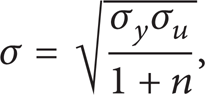
where n is the strain hardening exponent of the material, n = 0.2, and the plateau stress for AA6061-T4 adopted here is 139.9 MPa. The tensile stress-strain curve is shown in Figure 3.
The properties of face-sheets were represented by an elastoplastic material model (Mat 24 in LS-DYNA), which can accommodate an arbitrary stress-strain curve. In the model, the yield function φ is defined by the von Mises yield criterion as

where s ij is the deviatoric stress and σ y is the current radius of the yield surface expressed as
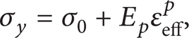
where εeff p is the effective plastic strain and E p is the plastic hardening modulus defined as

with E and E t the Young's modulus and tangential modulus, respectively.
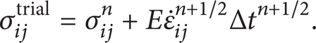
If the effective trial stress exceeds the yield stress then update the yield stress by

where the increment in the equivalent plastic strain Δε p is given by

Thus, the plastic strainat time step n + 1 is updated by:

The failure criterion is based upon the accumulated equivalent plastic strain associated to the von Mises flow rule in the constitutive model. Failure is assumed to occur when the equivalent plastic strain is equal to or higher than the failure strain in the tensile stress-strain curve of Figure 4, which is 0.18.
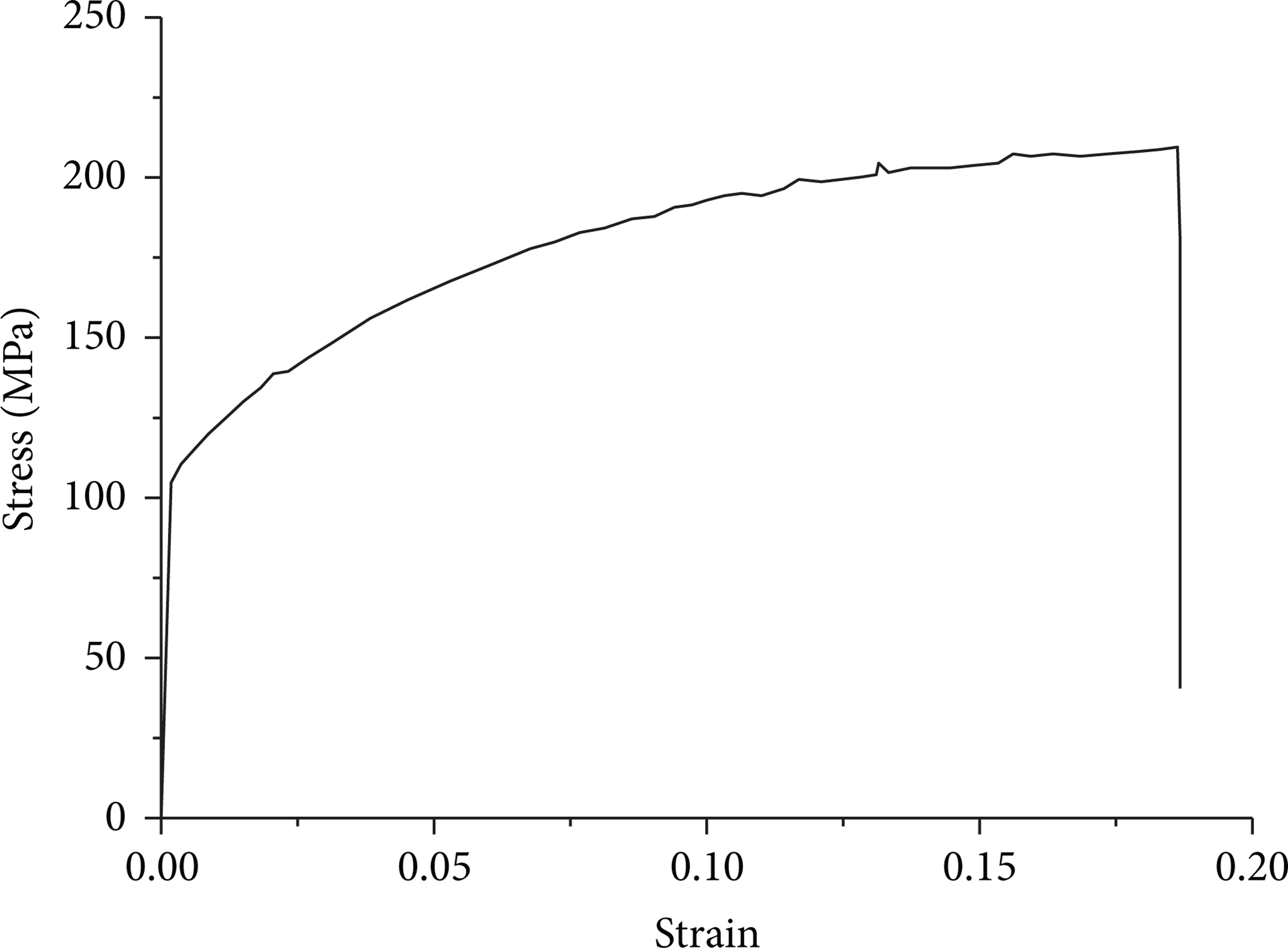
Tensile stress-strain curve of AA6061-T4.
Since the aluminum alloy is strain rate insensitive [32], the strain rate effect was neglected in the modeling. Also, the temperature effects were not taken into consideration based upon various evidence. Lee et al. [33] have shown that the temperature sensitivity of aluminium alloys is independent of the strain rate. In the work of Kapoor and Nemat-Nasser [34], it was shown that the temperature sensitivity of the flow stress of AA 6061 is very low, below 100°C. Lira and Scarpa [24] and Pasternak and Dyskin [25] have found that at an impact velocity of 845 m/s, the temperature of the target increases about 10% the melting temperature of its composing material. Considering that the melting temperature of AA 6061-T4 is between 582°C and 652°C, an increase in temperature of about 65°C in the target can be expected, and the change in the flow stress due to this much temperature change can be neglected.
3.1.2. Aluminum Foam Core
The CYMAT closed cell aluminum foam (Al-Si (7–9%)-Mg (0.5–1%)) was used for the sandwich core. Mechanical properties of the foam with three relative densities of 5%, 15%, and 20% are provided in Table 1.
Material properties of foam cores [12].

The aluminum foam was modeled by material model 63 in LS-DYNA, which is dedicated to model crushable foam with optional damping and tension cutoff. In this model, unloading is fully elastic and tension is treated as elastic-perfectly-plastic. The yield criterion of the material is defined as

where φ denotes the yield surface, σ y is the yield strength, and σ i trial and i = 1,3 are the principal stresses.
The Young's modulus is assumed constant and the stress is updated assuming elastic behavior.
Consider
The magnitudes of the principal values σ ij trial are i = 1,3 are then checked to see if the yield stress, σ y , is exceeded. If |σ i trial| > σ y , the stresses are scaled back to the yield surface as

A fracture criterion in which the principal stress is used for fracture evaluation was adopted [35]. The criterion is based on erosion of elements when the maximum principal stress reaches a critical value σcr. As the tensile failure stress of aluminum foam is approximately equal to the initial plateau stress σ p in compression [35, 36], σ p was used as the critical value of the principal stress; that is, σcr = σ p .
The stress-strain relationships of the aluminum foam with three relative densities used in the present work are provided in Figure 5, which were determined via standard compression tests [12]. These stress-strain curves were piecewisely sampled and used by material model 63 in the LS-DYNA models.

Uniaxial compression stress-strain curves of the CYMAT aluminum foam with different relative densities [12].
3.1.3. Auxetic Honeycomb Core
The auxetic honeycomb core in this study features a reentrant unit cell as shown in Figure 6. The Poisson's ratios v xy and v yx and the relative density ϖ of the auxetic honeycomb with this unit cell configuration can be computed as follows [37]:


where h is the hemline length, l the bevel edge length, t the wall thickness, and θ the reentrant angle of the unit cell (Figure 6). In the present work, the parameters determining the size and shape of the unit cell were chosen as h = 5 mm, l = 2.5 mm, and θ = 45°, which result in Poisson's ratios of v xy = – 0.55 and v yx = – 1.83, respectively, according to (11). Variation of the relative density of the auxetic honeycomb core is realized by adjusting the wall thickness of the unit cell. For the honeycomb cores with relative densities of 5%, 15%, and 20%, the corresponding cell wall thicknesses were obtained as 0.057, 0.171, and 0.228 mm according to (12).
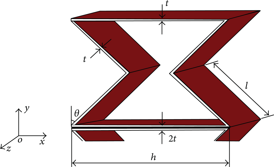
Auxetic honeycomb unit.
The behavior of honeycomb material is closely related to the properties of its base material. Here, the material of the auxetic honeycomb cores was assumed the same as that of the face-sheets, that is, aluminum alloy AA6061-T4. As such, material 24 in LS-DYNA was used to model the auxetic honeycomb core whose constitutive equations and failure criterion have been discussed previously.
3.2. Mesh Generation, Contact, and Boundary Conditions
Due to the symmetry of the problem, only half of the sandwich panel and the projectile were modeled to reduce computational expense. The face-sheets and the honeycomb core were modeled using Belytschko-Tsay 4-node shell elements with three integration points through the thickness. The aluminum foam core and the projectile were modeled by 8-node solid elements with reduced integration techniques. Hourglass control was used for all elements to eliminate spurious zero-energy modes.
It was found that a characteristic mesh size of 1.0 mm was able to satisfy convergence and numerical stability requirements for both AFP and AXP models. To provide detailed information on the contact interface between the projectile and the panel, a mesh convergence study was performed on this region. The mesh sensitivity was evaluated by carrying out successive space discretizations and analyzing the residual velocity of the projectile. The finalized mesh size of 0.5 mm in this region ensures equilibrium between computational efficiency and precision of the model in the prediction of residual velocity and damaged area. In total 9520 elements for both faces, 810 elements for the projectile, 145040 elements for the honeycomb core (24 mm thick), and 132360 elements for the foam core (24 mm thick) were generated. The AFP-projectile model included 141994 elements, while the AXP-projectile model had 155370 elements, as shown in Figure 7.

Finite element models of 1/2 sandwich panels with (a) aluminum foam and (b) auxetic honeycomb cores.
During the impact process, there exist three groups of contact between (i) projectile and face-sheets, (ii) projectile and core, and (iii) face-sheets and core. We have to correctly model the contact between any two bodies because they may interact with each other [38]. Automatic surface to surface [28] contact was applied to simulate the interaction between the projectile and face-sheets and the contact between the projectile and cellular cores. In this model, all nodes at the hemispherical end of the projectile are connected to the gap elements to monitor possible contact between the projectile and the sandwich panel. Rigid contact between the projectile and the sandwich panel took place when one or more nodes of the projectile fall, within a specified tolerance, in the deformed plane of the target plate on the impact side. The tied surface to surface offset model was used for contact between the face-sheets and the cellular core. The tied option glues the core's contact (slave) nodes to the face-sheets' target (master) surfaces and forces the slave nodes to follow the deformation of the master surfaces. The offset option was set to prevent initial penetration between face-sheets and core caused by shell thickness. The friction coefficient of 0.2 between all surfaces in contact was employed in the present work, since the interface friction has negligible influence on the ballistic response of similar structures [39, 40].
The influence of boundary conditions is usually negligible in high-velocity impacts [41]. In the present work, the sandwich panel was defined large enough to approximate the impact of a projectile on an infinite block. Thus, it was assumed that the three far end edges of the half finite element model were fully clamped while the impacted edge was prescribed with a symmetric boundary.
4. Numerical Results and Discussion
Depending on the energy level of the projectile, there are three damage patterns of a sandwich panel: (a) full perforation, (b) ballistic limit, and (c) partial perforation, as illustrated in Figure 8. Partial perforation means that the front face is penetrated, but the projectile remains embedded in the core eventually or probably has rebounded for a certain distance.

Different final situations of the projectile impacting on a sandwich panel: (a) full perforation, (b) ballistic limit, and (c) partial perforation.
The ballistic limit V b and the perforation energy E p are two critical indices for evaluating the perforation resistant and energy dissipating performances of a sandwich panel. The former is defined as the velocity when the projectile is either stuck in the back face or exits with a negligible velocity; the latter is essentially the energy absorbed by the panel during perforation [12]. If the elastic energy and the heat generated during the impact process are neglected, the perforation energy is equal to the kinetic energy loss of the projectile; that is,

where m p is the mass of the projectile and V i and V r are the initial and residual velocities of the projectile, respectively. When V r is assumed to be very small and near zero, the kinetic energy of the projectile is all dissipated by the sandwich structure. In this case, V b = V i , which is given by

If partical perforation occurs, energy absorption of the panel is equal to the initial kinetic energy of the projectile, that is,
4.1. Finite Element Model Validation
4.1.1. AFP Model Validation
In order to validate the finite element models, the ballistic impact experiments of AFPs reported in [12] were first simulated. The geometries and material properties of the projectile and AFPs in the finite element models were defined according to that of the tested specimens. The loading and boundary conditions were also set as in the tests. Figure 9 (a) compares the final damage patterns of the AFPs with different face-sheet thicknesses simulated by the FE models and those obtained in the tests. Clearly, the numerical predictions and the experimental results agree quite well. Figure 9 (b) plots the simulated and tested ballistic limits of the specimens, which also shows a good correlation between the two sets of results. These satisfying results indicate the numerical methods used were valid.

Comparison of numerical and experimental results of AFPs: (a) damage patterns and (b) ballistic limits.
4.1.2. AXP Model Validation
In this study, numerical methods for the AXP modeling were validated based on a quasistatic penetration test using an Instron Universal Testing Machine 5567 under displacement control at a crosshead speed of 0.1 mm/min. In the test, an auxetic honeycomb core of cross-section of 100 mm × 200 mm and thickness of 50 mm was first fabricated using 0.2 mm thick aluminum sheets. The unit cell had dimensions of h = 14 mm, l = 8.8 mm, and θ = 45° (refer to Figure 6). The auxetic core was then bonded to two 0.4 mm thick aluminum face-sheets using an epoxy adhesive and cured in room temperature for 24 h. Figure 10 (a) shows the final damage pattern of the specimen penetrated by a conical nosed steel indentor with a diameter of 35 mm, along with the simulation result. Penetration of the faces did not occur until the middle section of the specimen was largely compressed and the auxetic core concentrated around the tip of the indentor. Correspondingly, the load-displacement curve showed a flat shape at the beginning and attained a large peak in the final stage when the specimen was fully penetrated, as shown in Figure 10 (b). The good agreement between numerical results and experimental data proves the applicability and accuracy of the established finite element model of the AXP.

Comparison of numerical and experimental results of AXP under quasistatic penetration: (a) damage pattern; (b) load-displacement curve.
As the aluminum alloy is strain rate insensitive as described earlier [32], it was assumed in the present investigation that the numerical modeling techniques for quasistatic response of the AXP remain valid to provide reliable results for the dynamic response of the AXP subjected to high-velocity ballistic impact.
4.2. Parametric Study
Using the validated finite element models of the two types of sandwich panels, the effects of several key parameters on the ballistic limit and perforation energy are examined in the subsequent sections. These parameters include the impact velocity, face-sheet and core thicknesses, and the core density. In addition, comparisons are made between the AFPs and AXPs in various impact scenarios.
4.2.1. Effect of Impact Velocity
To study the velocity effect, nominally identical AFPs and AXPs (H f = 0.6 mm; H c = 24 mm; ϖ = 20%) were impacted by the projectiles at four impact velocities of 380, 425, 500, and 600 m/s. Based on the impact and residual velocities of the projectiles, the ballistic limit and energy dissipation were obtained. The panels' specifications and results are listed in Table 2.
Specifications and simulation results of AFPs and AXPs, which have identical configurations (H f = 0.6 mm; H c = 24 mm; ϖ = 20%) and loaded at various impact velocities, so that the effect of impact velocity can be studied.

Figure 11 shows the velocity evolutions of the projectiles in perforating the two types of sandwich panels at different initial impact velocities. Apparently, the perforation time is inversely proportional to the impact velocity for both panels. At the same impact velocity, it took a longer time for the projectile to perforate the AXP than the AFP. In addition, the velocity of the projectile decreased much faster in the auxetic panel. As a result, the residual velocity of the projectile is lower for the AXP than the AFP, especially at relatively low impact velocities. For instance, at V i = 600 m/s, velocity reduction of the projectile by the AFP is 52 m/s, while that by the AXP is 84 m/s, an 61.5% more reduction. At a relatively low impact velocity V i = 380 m/s; the velocity reduction by the AXP is 184 m/s, almost four times that by the AFP, which is 47 m/s. Figure 11 also shows that the residual velocity of the projectile perforating the AXP at V i = 500 m/s is close to that after perforating the AFP at V i = 425 m/s; the residual velocity after perforating the AXP at 425 m/s is even lower than that after perforating the AFP at 380 m/s. Furthermore, it is noted from Table 2 that the nominal ballistic limit of the AFP increases with increased impact velocity, while that of the AXP decreases as the impact velocity increases. Nevertheless, the actual ballistic limit of the investigated AXP was obtained as 340 m/s, 86% higher than that of the AFP, which is 183 m/s. It is, therefore, concluded that the AXP provides much better ballistic resistance than the AFP of the same dimensions and weight.
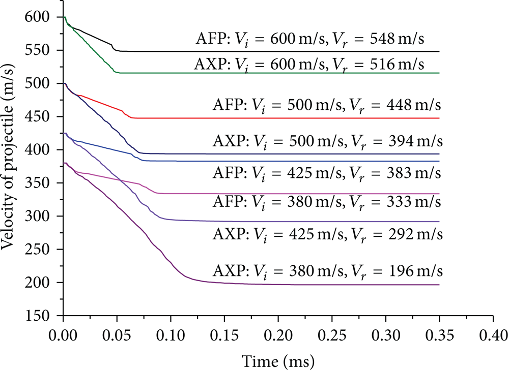
Variation in velocity of projectile versus time.
Figure 12 plots the energy absorption of the foam and honeycomb cores against the impact velocity, along with their corresponding sandwich panels. It is obvious that the energy absorption of the auxetic honeycomb core and AXP are significantly higher than that of their counterparts. Evident energy enhancement of the AFP with increased impact velocity is observed in the current simulations, as discovered through experimental tests [12, 42]. Interestingly, simulation results show that the AXP does not display any energy enhancement. On the contrary, the lower the impact velocity is, the more energy the AXP absorbs. Consequently, energy gap between the two panels becomes smaller at higher impact velocities.
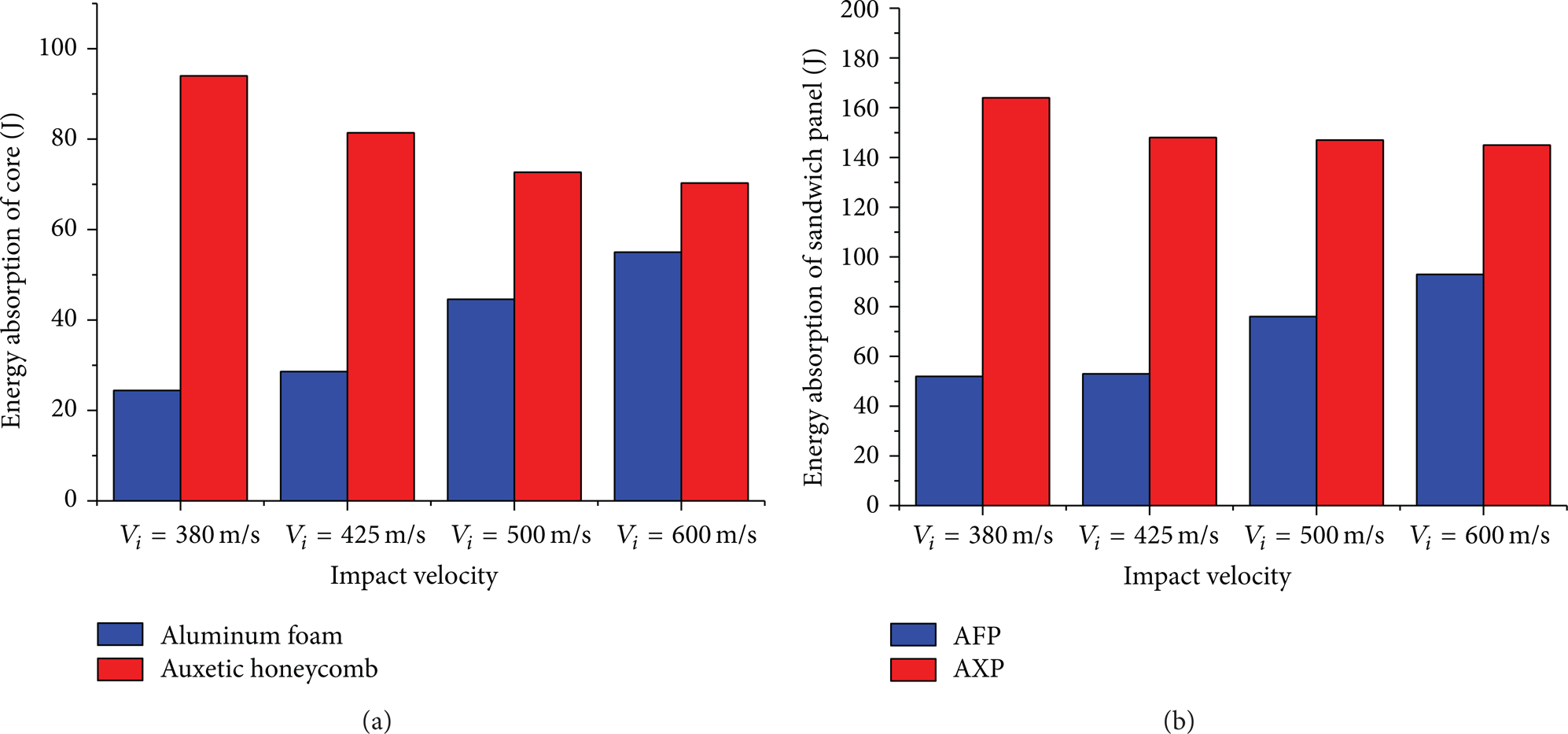
Comparison of energy absorption at different impact velocities (a) aluminum foam and auxetic honeycomb cores and (b) AFP and AXP.
The quantitative difference in ballistic resistance and the opposite reaction in energy enhancement of the two panels need to be further understood. Toward this end, damage patterns of the two panels at different impact velocities are first compared (Figure 13). It is seen that the front faces of both panels exhibit circular craters without global deformation. Localized tunnels are evident in the cores directly below the points of impact and through the thickness. More importantly, the influence of core configuration is clearly revealed by such a comparison. Firstly, the diameter of the tunnel is barely changed at different impact velocities in the foam core. This confirms to some extent the declaration in [42] that the energy enhancement is caused by the difference of compressive strain level of foam core reached before the perforation of top skin under different loading rates because of different face-foam core interaction mechanism. In contrast, the diameter of the tunnel in the auxetic core is affected by the impact velocity to some extent. As the impact velocity decreases the tunnel becomes larger, which indicates more material is involved during the impact for energy dissipation. This explains well the energy enhancement with decreased impact velocity in the auxetic honeycomb core as shown in Figure 12 (a). Secondly, it is clearly seen in Figure 13 that the diameter of the tunnel in the honeycomb core is almost twice that in the foam core. The more extensive damage area in the honeycomb core explains its much higher energy absorption than the foam core. Thirdly, the high energy dissipation of the honeycomb core at low impact velocity results in even lower residual velocity of the projectile (Figure 11) and leads to larger delamination area of the back face (Figure 13 (b)) which in turn contributes to the energy absorption of the AXP.
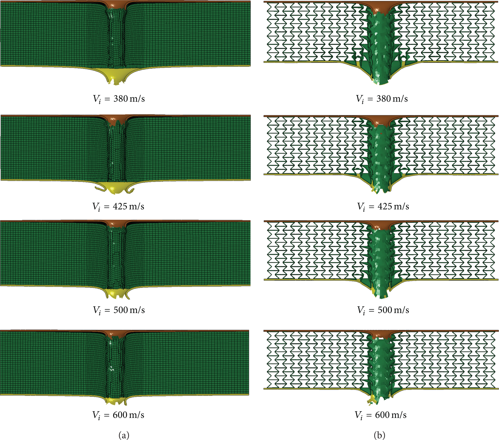
Damage patterns of (a) AFPs and (b) AXPs at impact velocities of 380, 425, 500, and 600 m/s.
For a better understanding of the enhanced ballistic resistance and energy dissipation of the auxetic honeycomb core, a close look was taken at the perforation process of the auxetic honeycomb under projectile impact. As shown in Figure 14, as the projectile goes in, the reentrant cells of the auxetic honeycomb contract laterally and the material flows into the vicinity of the impactor due to the negative Poisson's ratio effect. This movement creates an area of denser material directly below the point of impact (marked by blue circle in Figure 14) and results in additional resistance to ballistic impact. At the same time, higher energy absorption is expected because more material gets involved. When the impact velocity is relatively low, for example, near the ballistic limit of the AXP, the NPR behaviour of the auxetic core is brought into play thoroughly. However, at a high impact velocity, for example, V i = 600 m/s in current case, neighboring cells to the ones along the projectile path do not have adequate time to react before the projectile passes through the panel. In this case, the NPR effect of the auxetic core is not fully embodied. This explains the decreased ballistic limits and reduced energy absorption of the AXPs as well as the shrunked tunnels in the auxetic honeycomb cores at high impact velocities. Also based on this, the reduced energy gap between the two panels with increased impact velocity shown in Figure 12 could be understood.

Typical penetration process of auxetic honeycomb under projectile impact.
4.2.2. Effect of Face and Core Thickness
A total of twelve sandwich panels with three different face thicknesses and two different core thicknesses were simulated. The specimens were divided into four groups, and in each group the three AFPs (or AXPs) have identical core thickness (24 or 48 mm). The specifications of the panels and results are listed in Table 3.
Specifications and simulation results of four groups of AFPs and AXPs, each of which has identical core thickness (H c = 24 and 48 mm, resp.) and relative density ϖ = 15% but different face thicknesses (H f = 0.6, 1.0 and 2.0 mm, resp.), so that the effect of core and face thickness can be studied.

Note: negative velocity means a rebound of projectile by the back face.
The ballistic limit versus face thickness for the four groups is plotted in Figure 15. As expected, the panel with a thicker core and/or a thicker face results in a higher ballistic limit, for both AFP and AXP. Noticeably, the ballistic limit of AXP with H c = 24 mm in group 2 is much higher than that of the AFP with the same faces but twice the thickness (H c = 48 mm) in group 3. Using the ballistic limits of the AFPs with 0.6, 1.0, and 2.0 mm faces (groups 1 and 3) as the bench mark, for H c = 24 mm, the ballistic limit of the AXPs with the same face thickness (group 2) increases by 63.5%, 53.7%, and 58.7%, respectively, while for H c = 48 mm, the ballistic limit of AXPs with identical face (group 4) increases by 75.0%, 65.9%, and 62.6%, respectively. For all three face thicknesses (H f = 0.6, 1.0, and 2.0 mm), the difference between ballistic limits in groups 3 and 4 (H c = 48 mm) remains obviously larger than that in groups 1 and 2 (H c = 24 mm). This indicates that the thicker the core, the larger the advantage of AXP over AFP in ballistic resistance. Furthermore, increasing the face thickness, the ballistic limits of the sandwich panels with 24 mm and 48 mm cores tend to converge, for either AFPs or AXPs. This suggests that for sandwich panels with thicker faces, the relative contribution from the core decreases.

Ballistic limit versus face thickness for AFPs and AXPs with 24 and 48 mm core thicknesses.
The effects of face and core thicknesses on the damage patterns of AFPs and AXPs are shown in Figure 16. It is clearly seen that the auxetic honeycomb cores were more damaged than the foam cores for all face and core thicknesses analyzed. This resulted in more energy dissipation and higher ballistic limits of the AXPs (Figure 15). When the core is thinner (H c = 24 mm), the failure modes of the faces, especially the back face, were significantly affected by the face thickness. For instance, both faces were torn open with a number of petals for H f = 0.6 mm, whereas shear plugging failure was observed for both AFP and AXP with H f = 2.0 mm. In addition, larger area of damage was produced in the back face of the AXP than the AFP. Typically, significant global bending of the back face is seen in the AXP with H f = 2.0 mm, along with a significant delamination of over 50% area of the face sheet. In the cases with thicker cores (H c = 48 mm) as shown in Figures 16 (c) and 16 (d), the influence of face thickness becomes small. In all impact scenarios, the faces were damaged mainly by tearing except for one case in which the back face of the AXP (H f = 2.0 mm) was only dented due to partial perforation.
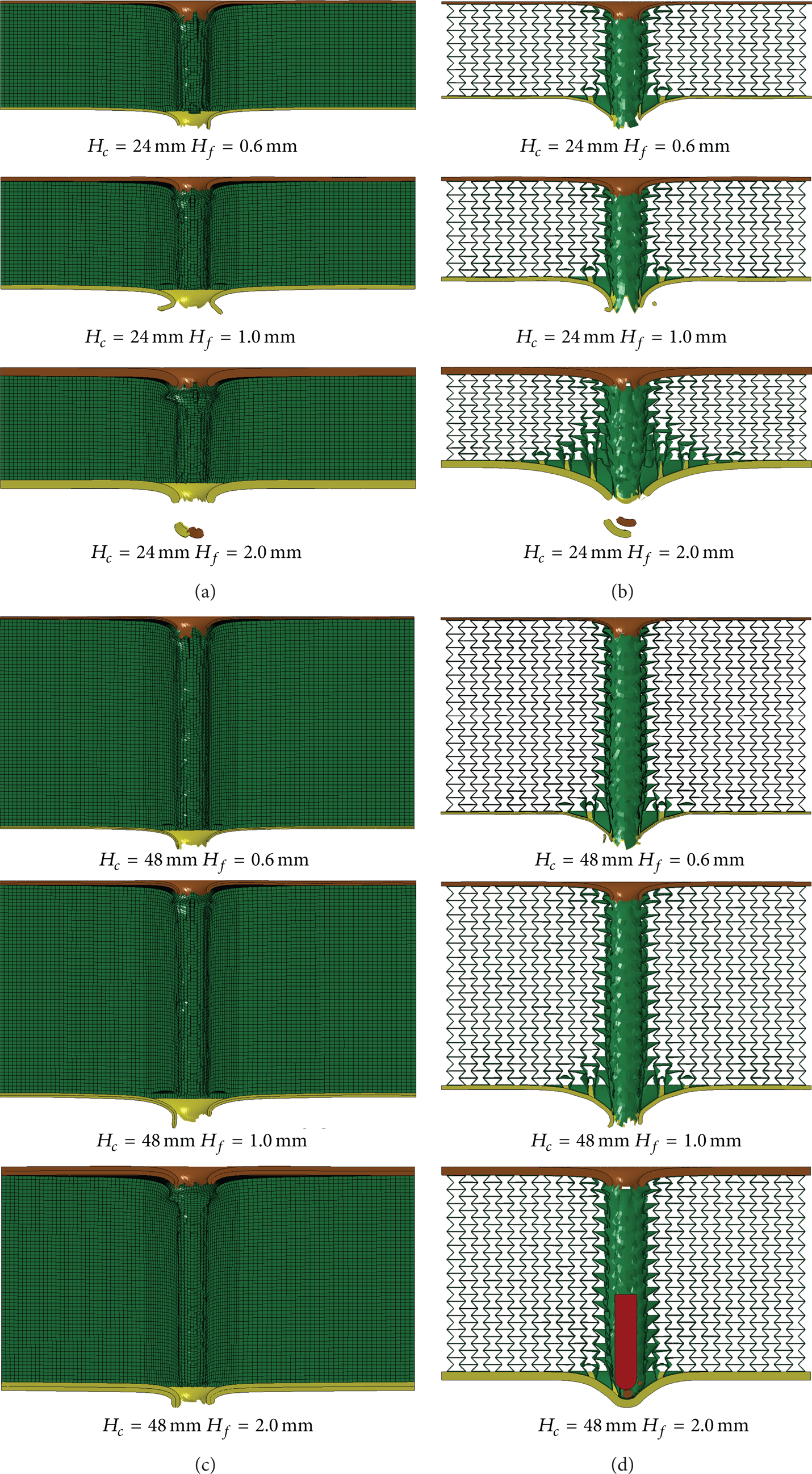
Damage patterns of sandwich panels with different face and core thicknesses. (a) group 1: AFPs with H c = 24 mm, (b) group 2: AXPs with H c = 24 mm, (c) group 3: AFPs with H c = 48 mm, and (d) group 4: AXPs with H c = 48 mm.
4.2.3. Effect of Core Density and Thickness
In this section, simulation results of twelve specimens are presented to study the effect of core density and thickness. The specimens were designed into four groups and in each of group the foam (or honeycomb) cores have identical thickness (24 or 48 mm), but different relative densities (5%, 15%, and 20%), as listed in Table 4, together with the simulation results.
Specifications and simulation results of four groups of AFPs and AXPs, each of which has identical core thickness (H c = 24 and 48 mm, resp.) and face thickness (H f = 1.0 mm) but different core relative densities (ϖ = 5%, 15%, and 20%, resp.), so that the effect of core density and thickness can be studied.

Figure 17 plots the relationship between the ballistic limit and core density for the two types of sandwiches with two different core thicknesses. Firstly, as one can expect, increasing the core density helps to increase the ballistic limits of both types of sandwich panels. Secondly, the figure reveals that the ballistic limit of the panel with a thicker core increases more rapidly with the relative density than their counterpart with a thinner core. For instance, the ballistic limit of the AXP with 24 mm core increases 38.8% from 214 to 297 m/s as the core relative density increases from 5% to 15%; With the same density increment, the ballistic limit of the AXP with 48 mm core increases 57.7% from 253 to 399 m/s. Moreover, this coupling effect of core density and thickness in affecting the ballistic limit is more evident for the AXPs than for the AFPs. The latter have been experimentally tested by Hou et al. [12]. Thirdly, for the same relative density the ballistic limit of AXP is much larger than that of the AFP with identical core thickness. And the superiority of AXP becomes more obvious as the core density increases. This can be explained as follows: as the density increases, the cell wall of the auxetic honeycomb becomes thicker such that the cells in the projectile path are more strongly connected to their nearby cells; this will lead to more apparent NPR effect and brings more material into the impacted region. In contrast, the foam core tends to fail more locally through shearing deformation under concentrated load, the increase of foam density has limited effect in ballistic resistance improvement. Last but not the least, for all three core densities (ϖ = 5%, 15%, and 20%), the difference between ballistic limits in groups 3 and 4 (H c = 48 mm) is larger than that in groups 1 and 2 (H c = 24 mm). This shows again that the positive relationship between core thickness and ballistic resistance is more evident for the AXP than the AFP, due to the different ballistic resistant mechanisms of the corresponding cellular cores.

Ballistic limit versus core relative density for AFPs and AXPs with 24 and 48 mm core thicknesses.
5. Conclusions
In this work, a type of aluminum sandwich panel with an auxetic honeycomb core for potential use against in-plane high-velocity projectile impact was proposed. The ballistic resistance of this auxetic-cored sandwich panel (AXP) was analyzed using the LS-DYNA finite element program. For comparison, the traditional aluminum foam-cored sandwich panel (AFP) of identical face and core configurations as the AXP was also included in the numerical study. The numerical modeling techniques for the AXP were verified by a quasistatic penetration test, while the finite element model of AFP was validated using the ballistic impact test results in the literature. Using the validated models, a parametric study has been carried out to examine the effects of impact velocity, face and core thicknesses, and core density on the ballistic limit and perforation energy of both types of sandwich panels. The main findings from the study can be outlined as follows.
(1) The AXP yields lower residual velocity of the projectile than the AFP, and the advantage of AXP becomes larger as the impact velocity decreases. The accumulation of auxetic honeycomb material below the point of impact due to the negative Poisson's ratio is the main cause of enhanced perforation resistance of the AXP.
(2) The impact velocity has profound effect on the ballistic limit and energy dissipation of both types of panels. Energy enhances evidently with increased impact velocity for the AFP as shown in [12, 42]. Energy absorption of AXP, however, decreases with increased impact velocity within the investigated range. The reason is that the honeycomb cells adjacent to the projectile path do not have adequate time to react, and the NPR effect is limited at higher impact velocities.
(3) Thickening the faces and/or the core results in higher ballistic limits for both panels. For the panel configurations considered, the ballistic limit of AXP is higher than that of the AFP with twice core thickness. The thicker the core, the larger the advantage of AXP over AFP in ballistic resistance. Increasing the face thickness causes the ballistic limits of the sandwich panels with 24 and 48 mm cores tend to converge, for either AFP or AXP, indicating reduced relative contribution from the core for ballistic resistance. Shear plugging is the predominant failure mode for the thicker face-sheet, while the thinner face tends to fail through torn open.
(4) Denser core leads to higher ballistic limit of the sandwich panel. Ballistic limit of the panel with a thicker core is more sensitive to core density variation, especially for the AXP. The superiority of AXP over AFP in ballistic resistance becomes more obvious as the core density increases.
This study has shown promising results of using the auxetic honeycomb as sandwich core for ballistic protection. Future studies such as design optimization of the AXP to further improve its ballistic resistant performance would be valuable.
Footnotes
Acknowledgments
This work is funded by the National Natural Science Foundation of China (nos. 50905024 and 51105053), the Liaoning Provincial Natural Science Foundation of China (no. 20102026), the Research Fund for the Doctoral Program of Higher Education of China (nos. 20090041120032 and 20110041120022), and the Fundamental Research Funds for the Central Universities (DUT13Lk47).