
Abstract
This paper presents kinematic analysis of a 3-axis parallel manipulator, called P3. The P3 parallel manipulator is developed based on a 3-PRRU parallel mechanism, where P denotes prismatic pair, R revolute pair, and U universal joint. The P3 parallel manipulator can undergo two rotations and one translation without parasitic motion. First, a brief description of the P3 is presented. Then, forward and inverse kinematic solutions of the P3 are derived. Parasitic motion is discussed. The Jacobian matrix is obtained based on the velocity equations. Further, singular configurations of the P3 are identified. A special configuration where the actuation fails is also detected based on screw theory. The workspace of P3 is investigated.
1. Introduction
When a PM (parallel mechanism) has less than six DOF (degrees of freedom), it is called a lower-mobility parallel mechanism. The 3-DOFs PM with one translational DOF and two rotational DOFs is an important category of the lower-mobility PM. Such a kind of PM can be constructed by using three legs generating a planar-spherical kinematic bond [1]. Hence, such a kind of PM can be called 3-[P][S] PM. The 3-[P][S] family includes four typical types of architectures, namely, 3-RPS, 3-PRS, 3-RRS, and 3-PPS, where R denotes a revolute pair, P a prismatic pair, and S a spherical joint. Note that the 3-[P][S] PM is also called [PP]S PM [2].
Since the 3-RPS PM was proposed [3], the 3-[P][S] family has been used extensively because many tasks require one translational DOF and two rotational DOFs (1T2R). For example, Z3 head in machine tool [4], telescope application [5], motion simulator [6], micromanipulator [7], and coordinate measuring machine [8]. Much progress regarding kinematics analysis [9–12], dimensional synthesis [13–17], singularity [18, 19], dynamics [12, 20, 21], and parasitic motion [22] has been obtained. Particularly, a new 1T2R PM with motion bifurcation of the end tool proposed for machine tool application [23].
Parasitic motion is an important kinematic feature of the 3-[P][S] parallel mechanism. Carretero et al. [22] defined parasitic motion of the 3-PRS PM as the motion occurring in the constrained DOFs, including one rotation about the z-axis of the fixed frame and two translations along the x and y axes of the fixed frame. Though the amplitude of parasitic motion is often small, it may exert negative effects on manipulation accuracy and quality. For instance, when the 3-PRS PM is used in a telescope to perform tipping/tilting and focusing of the secondary mirror, the parasitic translations in x and y axes are unwanted displacements and cause image aberrations. Actually, the x and y parasitic translations cannot be compensated or corrected by the control system of a 3-PRS PM.
As it is pointed out in [24], the motion of a [P][S] PM without parasitic motion can be expressed as a product like {
The P3 parallel manipulator is developed based on a 3-PRRU PM belonging to the new family of the 3-[P][S] PM without parasitic motion proposed by Li and Hervé [24]. Moreover, the rotation center of the moving platform of the P3 is constrained to move in a line, and two rational axes can be specified. This fact means that the translation and rotations are decoupled and simple control can be achieved. Besides, the 3-PRRU parallel mechanism has no parasitic motion because of the constrained path of the rotation center. Thus, the P3 parallel manipulator is a simple-to-control PM without parasitic motion and has great potential in application.
2. Description of the P3 Parallel Manipulator
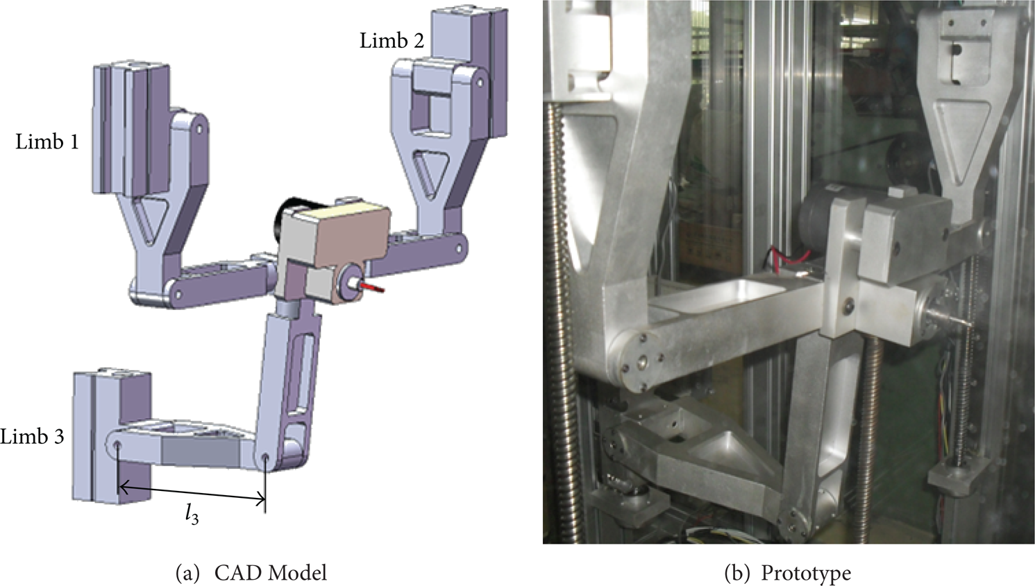
The prototype of the P3 parallel manipulator is shown in Figure 1. The P3 parallel manipulator is developed based on a 3-PRRU parallel mechanism as shown in Figure 2. In Figure 2, I is the base platform and Π is the moving platform. The moving platform is connected to the base through three identical PRRU limbs.
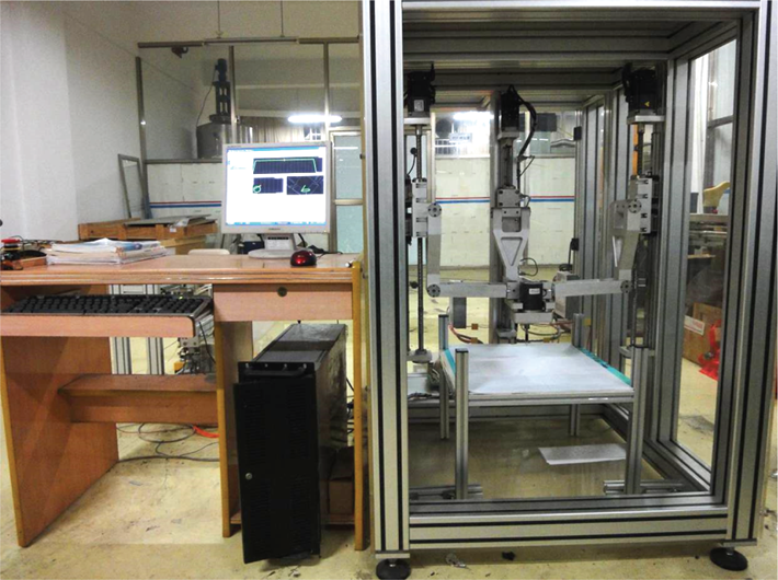
Prototype of P3 parallel manipulator.

3-PRRU PM.
The three prismatic pairs that are connected to the base are actuated and parallel to each other.
There are two revolute joints at the end of each link A i B i , and one is connected with the prismatic joint and the other is connected with link B i C i . At the end of B i C i , there is a universal joint, which is connected with the base platform. Counting from the moving platform, the first revolute axis of the universal joint is perpendicular to the moving platform.
The fixed base frame is denoted by O-xyz, and the moving frame is denoted by O′-uvw, as shown in Figure 1. Plane A i B i C i is called the ith limb plane (LP). Note that the three planes, A1B1C1, A2B2C2, and O-xz, are coincident and the directions of the revolute joints are parallel to y axis. A3B3C3 and O-yz are the same planes in which the directions of the revolute joints are parallel to x-axis. The first revolute axis of the universal joint is perpendicular to the base platform and the second revolute axis of the universal joint is parallel to the base platform in each limb. The length of the tool which is installed at the center of the moving platform is H. The parameters of P3 parallel manipulator are listed in Table 1.
Parameters of the P3 parallel manipulator.

3. Position Analysis
3.1. Forward Kinematics
The forward kinematics require finding the location and orientations of the moving platform given the input d i . In this work, we use a y-x-z Euler angle about the moving frame to describe the orientation of the moving platform. The rotations are defined as follows: (i) rotation by an angle θ about y-axis, (ii) rotation by an angle ψ about the new x-axis, (iii) rotation by an angle φ about the new z-axis. The rotation matrix is given by
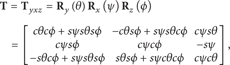
where c* and s* correspond to cos (*) and sin (*), respectively.
The fact that the 3-PRRU PM has no parasitic motion was explained by Lie's group theory in [25]. Here, we present a brief kinematic analysis for the reader's sake and show that such a property can simplify the following analysis. As shown in Figure 2, in the initial configuration, the axes of the base frame are parallel to the axes of the moving frame, respectively. Moreover, z and w are collinear.
Because the points C i can only move in the limb plane, we have the following three constraint equations for each leg:

Apparently, we have

Solving the above equations yields

Because ψ represents a continuous rotation of the moving platform, we have ψ ≠ 0 and φ = 0. Hence, the three parasitic motions are all equal to zero and the P3 parallel manipulator has no parasitic motion. Therefore, the rotation matrix can be simplified as follows:

Then, let us focus on limb 1 and limb 2, as shown in Figure 3.

Sketch of limb 1 and limb 2.
When d1 and d2 are given, all the parameters in Figure 3 can be obtained:

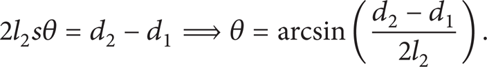
Substituting (7) into (6) yields


Focusing on limb 3 as shown in Figure 4, we can use the x-y-z Euler angle to describe the orientation of the moving platform. The three rotations are defined as follows: (i) rotation by an angle γ about u-axis, (ii) rotation by an angle θ3 about the new v-axis, (iii) rotation by an angle θ4 about new w-axis. The rotation matrix is:


Sketch of limb 3.
When d3 is given, all the parameters in Figure 4 can be obtained. Thus, we have

Then, sγ and cγ can be obtained from (11).
Although we use different Euler angles to describe the orientation of the moving platform, the rotation matrices are the same. Hence, we have (10) = (5) and
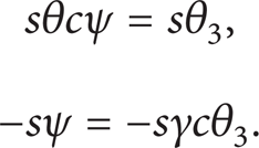
Then

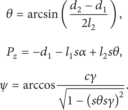
Hence, the forward kinematics are as follows:
Actually, there are two possibilities in the limbs 1 and 2 when the limb lengths d i are given. As shown in Figure 3, the broken line is another possible configuration. And each possibility also has two consequences in the limb 3; see the broken line in Figure 4. Therefore, there are four solutions in the forward kinematics.
3.2. Inverse Kinematics
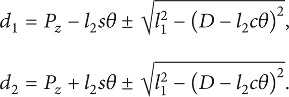
The inverse kinematics require finding the limb length d i given the location and orientations of the moving platform. As shown in Figure 3, when P z , θ, and ψ are given, we have
Further, focusing on limb 3 in Figure 4, we have

Then,

where γ can be calculated by (8):
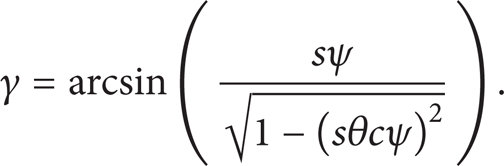
Apparently, every limb has two possibilities and the inverse kinematics have eight solutions. The “±” in (15) and (17) should be “+” in this text. So, we have

3.3. Tool Position
As shown in Figure 2, the length of the tool is H. The coordinate of G in the moving frame is

4. Forward and Inverse Velocity Analysis
Differentiating both sides of (14) with respect to time yields

where

So, we can establish the velocity equation of the 3-PRRU PM as follows:
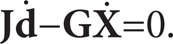
Hence, we have
Obviously, (24) describes both the forward and inverse velocity relations of the 3-PRRU PM.
5. Singularity Analysis
Singularity is an intrinsic property of a PM. When the PM is at its singular configuration, it will lose or gain one or more degrees of freedom and become incontrollable or lose its stiffness. There are three types of singularity based on the rank deficiency of the matrices
5.1. Inverse Kinematic Singularities
An inverse kinematic singularity occurs when the determinant of
Inverse kinematic singularity.
5.2. Direct Kinematic Singularities
A direct kinematic singularity occurs when the determinant of

Direct kinematic singularity.
5.3. Combined Singularities
A combined singularity occurs when the determinants of

Combined singularities.
6. Actuation Failure
When the moving platform is upright, as shown in Figure 8, the actuations in limb 1 and limb 2 fail. In other words, the mobility of the 3-PRRU PM is the same while the three motors cannot determine the position and orientation of the moving platform. Such a phenomenon is called actuation failure and can be investigated by screw theory.

Actuation failure configuration.
The modified Grübler-Kutzbach criterion is applicable to mobility analysis of all kinds of lower-mobility PMs [28]. The modified Grübler-Kutzbach criterion is given by

where M denotes the mobility of a mechanism, d is the order of a mechanism, n is the number of links including the frame, g is the number of kinematic joints, f i is the number of freedoms of the ith joint, v is the number of redundant constraints except those forming common constraints, and ζ is the number of local freedoms.
The order of a mechanism d is given by

where λ is the common constraint of the mechanism.
A common constraint can be defined as a screw reciprocal to the unit twists associated with all kinematic pairs in a lower-mobility PM. Geometrically, a common constraint can be interpreted as a constraint formed by coaxial limb constraints of the same kind.
For convenience,
As shown in Figure 9, we establish a limb reference coordinate system denoted by O1-X1Y1Z1 when the moving platform is upright. Then, the twist system of limb 1 is given as follows:
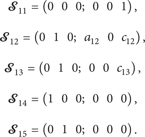

First limb twist system.
Using reciprocal screw theory, we can obtain the limb constraint system as
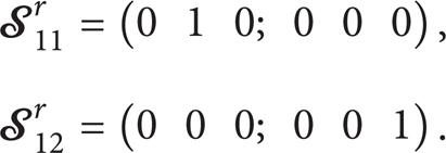
Note that
Note that in this configuration, the direction of the prismatic joints in limbs 1 and 2 is perpendicular to the three revolute joints
Similarly, we can establish another limb coordinate system O0-X0Y0Z0 for limb 3, as depicted in Figure 10. The twist system of limb 3 is given by


Third limb twist system.
The limb constraint system of limb 3 can be obtained:

The

Constraint system.
The five limb constraints form the mechanism constraint system. The combined effect of them can be represented by the standard base of the mechanism constraint system, which is given by

The three wrenchs in (31) constrain two translations of the moving platform along X0 and Y0 axes and one rotation about Z0, respectively. There are no common constraints, and λ = 0. Two redundant constraints exist and v = 2.
Hence, the mobility of the 3-PRRU PM is

Although there are redundant constraints and local freedoms in this configuration, the number and pattern of the DOF are the same as the common configuration. Therefore, this configuration is not a singular configuration, but a configuration where the actuation fails. However, if l3 < E, the moving platform will never be upright. Such a design is implemented in the prototype.
7. Workspace Analysis
The P3 PM has two rotational DOFs and one translational DOF. The moving platform can rotate about two axes intersecting at a point which is determined by the translation in Z. In other words, the two rotations are decoupled with the translation. Hence, we can investigate the workspace without considering the translation.
7.1. Tilt Ability
The tilt ability of the P3 PM is defined as the scope of the pose of the moving platform and is described by the maximal scope of θ and ψ. Note that the Jacobian matrix is not singular when the P3 PM is in the configurations shown in Figure 12. However, dexterity is very bad in these configurations, as shown in Section 8. Therefore, we choose the two configurations as the right and left limits.

The left and right limit.
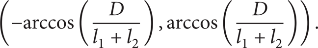
As shown in Figures 3 and 12, when the mechanism is between the two limits, the scope of θ is
Equation (13) shows the relation between θ and ψ. By using the conclusion of singularity analysis, we can also obtain the scope of the ψ. As shown in Figure 8, A3B3 and O′B3 are collinear, and the mechanism is at its singular configuration. At this configuration, ψ reaches its upper limit value.
We have


There are two possibilities when ψ reaches its lower limit value.
l3 ≥ E: when the moving platform is upright, as shown in Figure 8, actuation failure occurs. At this configuration, γ = – 90°.
l3 < E: the PM will never be upright. But when A3B3 is horizontal, as shown in Figure 5, the mechanism is at the inverse kinematic singularity configuration. We have

Using (13), we can find the lower limit value of ψ.
In order to increase the tilt ability, we can maximize the scope of θ and ψ. From (33), the scope of θ can be enlarged by increasing l1 + l2 or decreasing D: From (34) and (35), the scope of ψ can be enlarged by increasing l3 + l4 or decreasing E: From (36), it is known that when l3 < E, the scope of ψ can be enlarged by increasing l3 and l4 until l3 = E.
The scope of θ can be calculated by (33). Because l3 < E, the upper and the lower-limit values of ψ can be obtained by (34) and (36). The tilt ability of 3-PRRU PM is depicted in Figure 13.
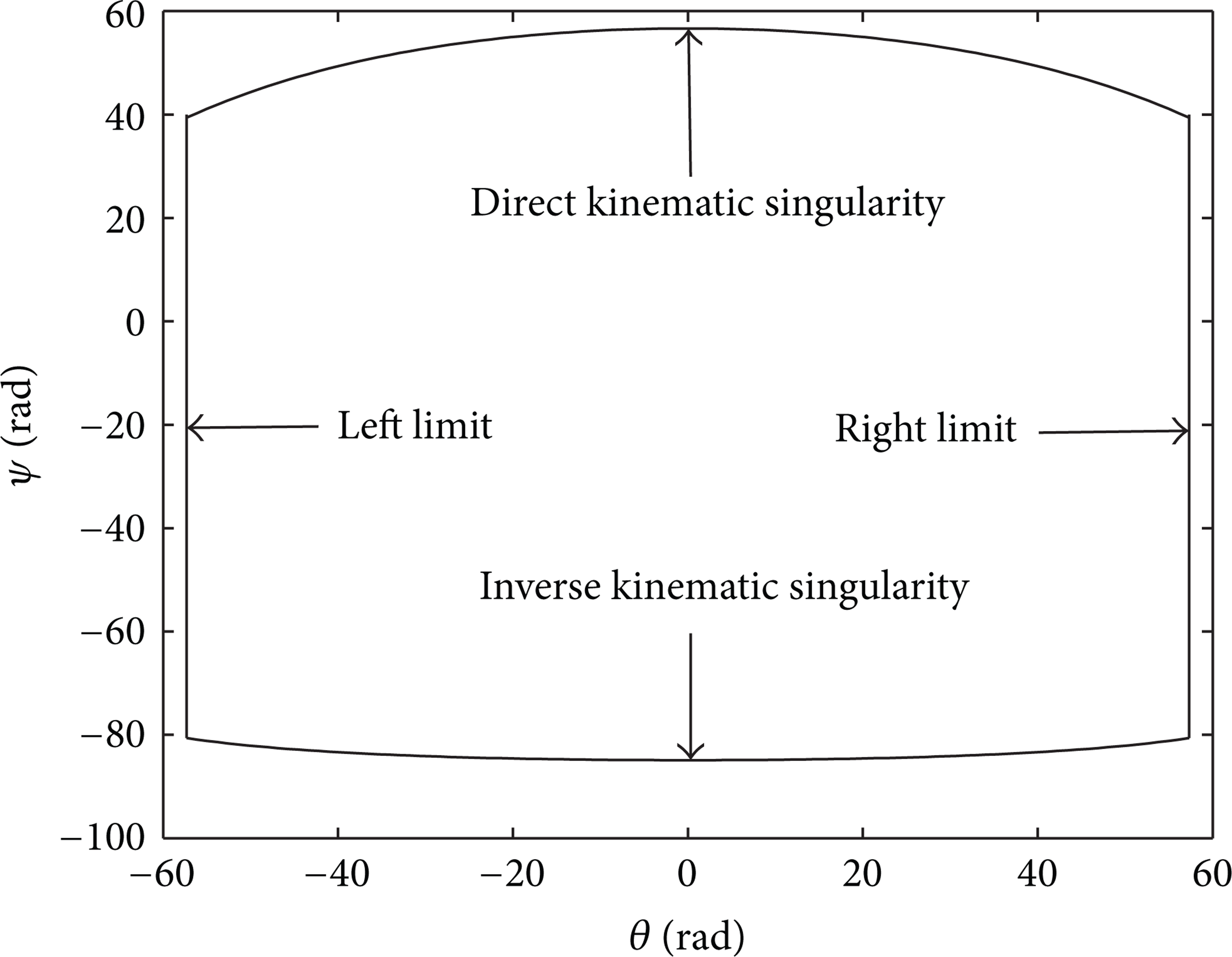
The tilt ability.
The area surrounded by curves is the poses where the 3-PRRU PM can reach. The lower curve means the inverse kinematic singularity when ψ is close to – 80°; see Figure 5. The upper curve means the direct kinematic singularity when ψ is close to 50°; see Figure 6. The two lines in the right and left of the picture mean the two configurations shown in Figure 12.
7.2. Tool End Workspace
When P z is given, the tool end workspace is determined by the tilt ability which has already been described by (33)–(36). Using (20), we can find the tool end workspace. When P z is given, say P z = – 200, the tool end workspace is a part of spherical surface, as shown in Figure 14.

Tool end workspace (P z = – 200).
8. Conclusion
This paper presents the kinematic analysis of a 3-axis PM, called P3. The forward and inverse kinematics are presented. There are four solutions in the forward position analysis and eight solutions in the inverse position analysis. The inverse, direct, and combined kinematic singularities of the P3 PM are identified. It is also shown that the actuation failure can occur and can be avoided at the design stage by selecting appropriate link dimensions. The tilt ability and workspace of the P3 prototype are presented. The P3 has no parasitic motion and simple control can be achieved.
Footnotes
Acknowledgments
This project is supported by the National Natural Science Foundation of China (Grant nos. 50905167 and 51075369) and Zhejiang Provincial Natural Science Foundation of China (Grant no. R1090134).