
Abstract
The line-structured light vision sensor has been used widely in industrial vision measuring fields due to its simple structure, small volume, light weight, low cost, convenient calibration, and high accuracy of measurement. To locate the reference sphere precisely with line-structured light vision sensor, a mathematical model based on the measuring principle of line-structured light vision sensor is established in the paper. Then, the positioning measurement error is analyzed in detail. The experimental results show that the method is valid and correct. In addition, an accurate measurement area which is from R0 × sin 45° to R0 × sin 75° away from the center of reference sphere is delimited through the statistical analysis of the experimental data. For the robot temperature compensation and calibration of flexible vision measurement system, this method effectively solves the positioning measurement problems about reference sphere with line-structured light vision sensor and has been applied in the industrial flexible online measurement systems successfully.
1. Introduction
The line-structured light vision sensor consists of a line structured light projector (linear laser) and a camera [1]. This type of sensor has many advantages, such as simple structure, small volume, light weight, low cost, convenient calibration, and high accuracy of measurement. Hence, it is widely used in the industrial vision measuring fields [2, 3]. In particular in the flexible measurement system based on industrial robots [4], the line-structured light vision sensor has more prominent advantages at the aspect of flexibility and spatial accessibility than the stereo visual sensor (binocular or multi-camera vision sensor).
In the flexible online vision measurement system, each robot is configured with one line-structured light vision sensor generally. In principle, just the point in the structured light plan can be a positioning measurement. However, there are various types of the measured characteristics, such as edge (inflection point) [5], round hole (or ellipse hole) [6, 7], square hole (or rectangular hole), and sphere. Liu et al. [8] studied seam tracking based on a line-structured light vision sensor. Wu et al. [7] proposed a two-step method for spatial circle orientation with a line-structured light vision sensor and analyzed the orientation errors in detail. Theoretically, this method can also realize the spatial measurement of the symmetrical features, such as elliptical hole, square hole, and rectangular hole. However, few scholars have researched about the reference sphere positioning measurement with the line-structured light vision sensor.
Industrial robot is the motion platform in the flexible online measuring system. It is well known that industrial robot has high position repeatability but low absolute positioning accuracy [9]. In addition, every joint motor can generate a large amount of heat with the robot moving, which leads to the significant changes of robot joint length and other robot parameters [10]. Due to the extreme complexity of the joint temperature distribution, it is difficult to establish an accurate temperature distribution model for the calculation of parameters that change. The external auxiliary devices are generally introduced into the system for robot parameters calibration and temperature compensation [11]. The reference sphere is a spatial geometry symmetrical object. So there is no strict posture requirement for the vision sensor during the positioning measurement. During the robot parameters calibration and temperature compensation, the sphere is an ideal auxiliary object, and its center acts as the physical constraint of fixed point in the measurement space. Franke et al. [9] used four spheres with a known diameter and center points as the calibration objects for exterior orientation. Guo et al. [11] used the center of the sphere as the global control point in the measured field to compensate the positioning error of the robot. Therefore, the accurate positioning measurement method of the reference sphere with the line-structured light vision sensor is essential for the robot temperature compensation and parameters calibration.
To locate the reference sphere precisely, a mathematical model based on the measuring principle of the line-structured light vision sensor is established in the paper. Then, the positioning measurement error is analyzed in detail. Finally, experiments are carried out to verify the effectiveness of the mentioned measurement method and its measurement accuracy. Meanwhile, an accurate measurement area is delimited through the statistical analysis of the experimental data.
2. Measuring Principle of the Line-Structured Light Vision Sensor
The line-structured light vision sensor contains a line-structured laser and a camera. The line-structured laser projects a fan-shaped light plane in space, which intersects with the measured characteristics. The camera captures the light stripe image modulated by the characteristics, and 3D coordinates of points in the light stripe can be derived by image processing, triangulation measuring principle, and mathematical model of the line-structured light vision sensor.
As shown in Figure 1, O
w
– x
w
y
w
z
w
is the 3D world coordinate frame, and O
c
– x
c
y
c
z
c
is the camera coordinate frame. Note that O
c
is the optical center of the camera, the x
c
axis and the y
c
axis are in keeping with the increasing direction of column and row on the image plane, respectively, and the z
c
axis is the optical axis of the camera. In addition, the image plane π
n
is perpendicular to the z
c
axis and has a distance of 1 to O
c
. O
n
– x
n
y
n
is assumed to be the 2D image plane coordinate frame. O
n
is the intersection of the image plane π
n
and the optical axis z
c
. The x
n
axis and the y
n
axis are parallel with the x
c
axis and the y
c
axis, respectively. Let the camera coordinate frame O
c
– x
c
y
c
z
c
be the sensor coordinate frame, so the equation of the light plane π
s
in O
c
– x
c
y
c
z
c
can be used as the mathematical model of the line-structured light vision sensor. Assume that a point P
s
is on the light plane π
s
and its 3D coordinate in O
c
– x
c
y
c
z
c
is

where

Measurement model of line-structured light vision sensor.
If P
n
is the ideal projection of P
s
on π
n
, then P
s
, O
c
, and P
n
are collinear [16]. Let homogeneous coordinate of P
n
in O
n
– x
n
y
n
be
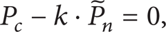
where k is an arbitrary constant, except zero.
If
The relationship between O c – x c y c z c and O w – x w y w z w follows the rigid body coordinate transformation, which can be built by means of auxiliary target [17].
3. Mathematical Model of Reference Sphere Positioning Measurement
According to the measuring principle, the line-structured light vision sensor can measure the points on the light plane, but it cannot apply to the points out of the light plane [18]. When the light plane is projected on the reference sphere and the intersecting cross-section is the maximum circular cross-section π0 in the sphere surface, 3D coordinates of points in the circumference of the largest cross-section can be obtained directly by the line-structured light vision sensor measuring model. If the 3D coordinate of a point in the cross-section circumference is

where R0 is the radius of the reference sphere and
In the actual process of the reference sphere positioning measurement, it is difficult to meet the requirement that the light plane intersects with the maximum circular cross-section. As shown in Figure 2, O0 is the center of the reference sphere. The actual intersecting cross-section of the light plane and the reference sphere is π
l
. In the fitting circular cross-section, the center of the fitting circle is


Actual reference sphere positioning measurement.
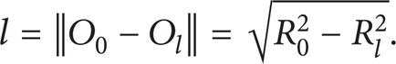
The maximum circular cross-section π0 is parallel with the actual intersecting cross-section π l . l is defined as the distance between π0 and π l ; then,
The normal vector
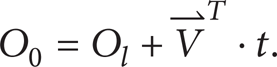
From (4) to (6), (7) can be derived as follows:

Combining (7) and (6), the coordinate of O0 can be obtained.
4. Error Analysis of Reference Sphere Positioning Measurement
In Figure 3, the angle between light plane and the surface normal at the measured point is defined as the projected angle α.
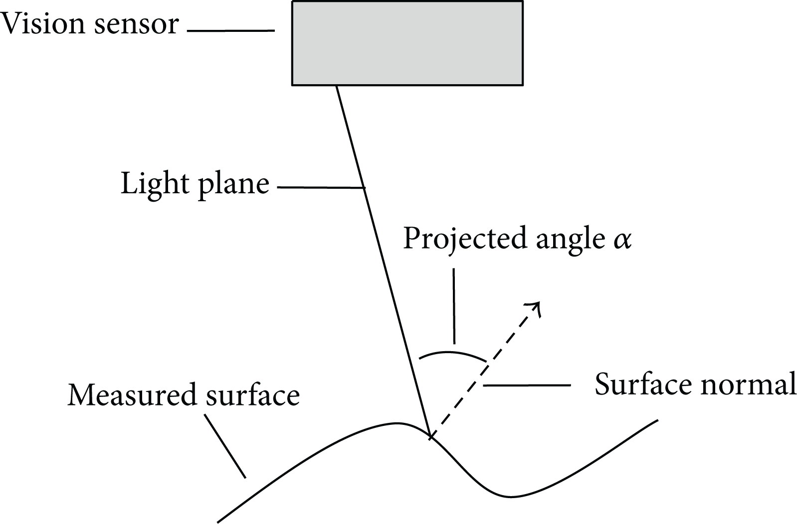
Definition of projected angle.
As shown in Figure 4, the light plane intersects with the reference sphere. Assume that point A is an arbitrary point on the circular cross-section. O0 is the center of the reference sphere. O l is the center of the intersecting circle. The surface normal vector of the spherical surface at the point A is consistent with the direction vector of line O0A. The direction vector of line O0O l is perpendicular to the plane π l . According to the above definition, ∠O0AO l is the projected angle at point A:


Projected angle in sphere.
According to (8), the projected angle α varies with the different R l , which represents the different intersecting section of the light stripe and the spherical surface. However, all points on an intersecting sections have the same projected angle α. The curve that described the relationship between the projected angle and the radius of the circular cross-section is shown in Figure 5.
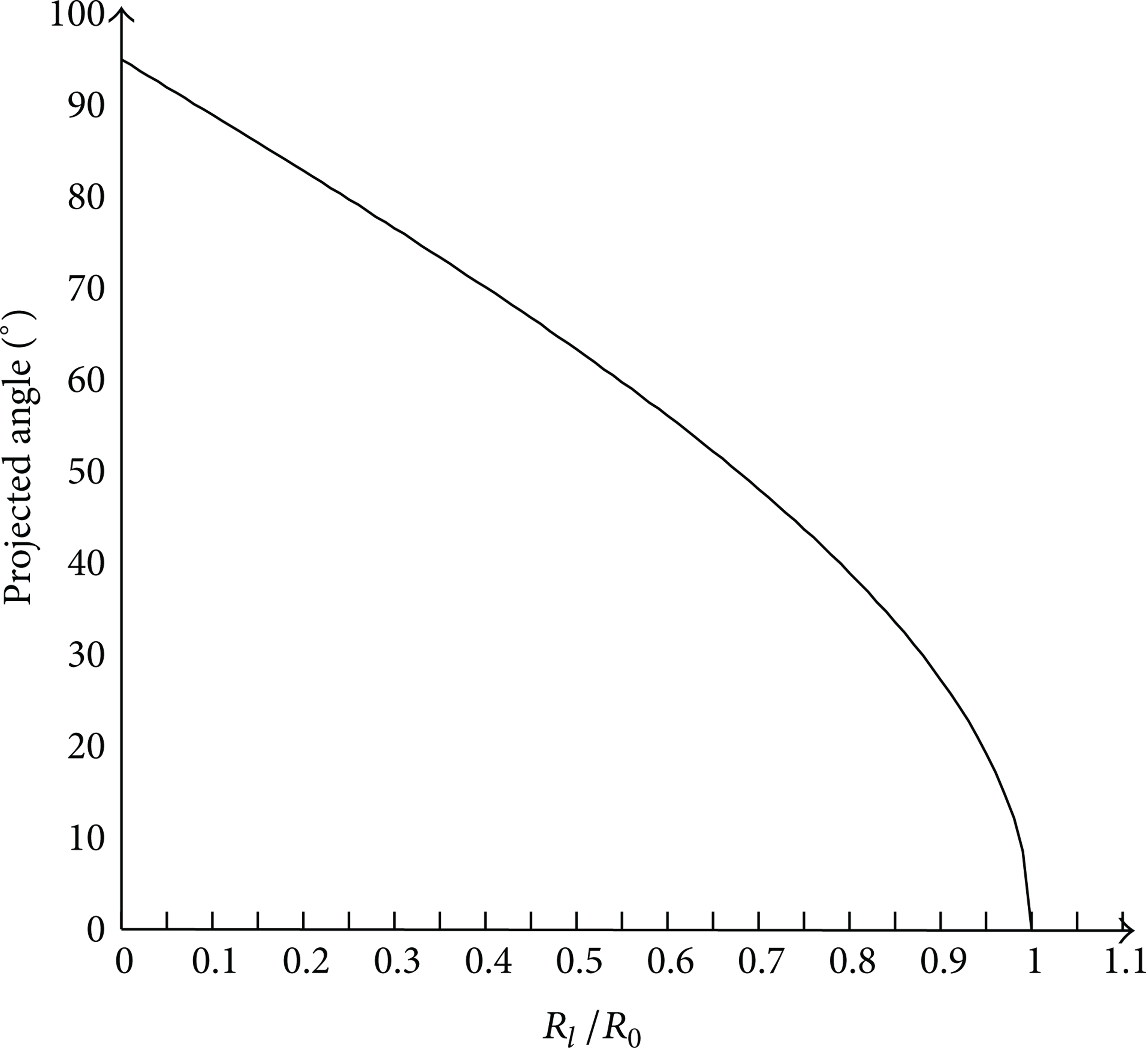
Relation curve between the projected angle and the radius of the circular cross-section.
As shown in Figure 5, when the light plane is tangent with the reference sphere, namely, R l = 0, there is α = 90°. The projected angle α reduces gradually with the light plane approaching to the maximum circular cross-section. When the light plane intersects with the reference sphere on the maximum circular cross-section, namely, R l = R0, there is α = 0°. The curve has approximate linear variation within a wide range. But when the light plane is near to the plane π0, the projected angle α reduces quickly.
The actual light stripe which is produced by a semiconductor laser has the thickness, so the intersecting circular cross-section on the reference sphere surface has a certain width. Taking into account the factor of the projected angle, there will be a deviation between the geometric centers of light stripes which are in the measurement image and on the sphere surface, respectively. The larger the projected angle is, the much more deviation will be caused [19, 20]. Thus, a salient deviation can be yielded by a larger projected angle α when light plane is close to the edge of the sphere. The deviation will reduce the accuracy of the fitting result of R l , the calculation of l, and the reference sphere positioning measurement finally.
The errors of R l and l caused by the above deviation are defined as ΔR l and Δl, respectively. The derivative of (5) is taken, and the relationship between Δl and ΔR l is obtained:

In Figure 6, the curve indicates that

5. Experiments
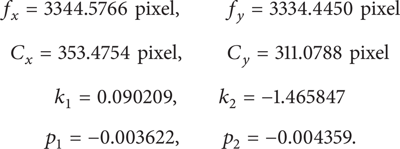
Experiment setup is shown in Figure 7. The line-structured light vision sensor is mounted at the end effector of the robot. The reference sphere is fixed at a one-dimensional electric displacement rail whose repetitive positioning accuracy is less than 3 μm, and the resolution of its grating ruler is 1 μm. The reference sphere is ZrO2 ceramic ball (level G10, GB308-2002/ISO3290-1998) attached with developer, with a diameter of Ø25.4 mm. The line-structured light vision sensor is composed of a TELI CS8620BCi camera made by Toshiba, a customized lens, and a linear semiconductor laser LH650-4-5 made by Huanic. The spatial resolution of the camera is 768 × 576 (pixel), and the pixel size is 8.6 × 8.3 (μm). The customized lens contains a piece of narrow-band pass filter that the central wavelength is 650 nm, and the half-width of the bandpass wave is 10 nm. The central wavelength of the semiconductor laser is 650 nm and the line width is less than 1 mm at the working distance of sensor. The parameters of the camera are calibrated precisely as follows:

Experiment setup.
The structure parameters of the line-structured light vision sensor are expressed as

Above all, adjust the robot pose to meet the following requirements. The reference sphere is in the sensor's field of view and also at its working distance. The image plane of the camera is parallel with the plane of the guide rail roughly, and its horizontal direction is consistent with the moving direction of the guide rail. Then, stop the industrial robot to ensure the sensor is still. The reference sphere moves at several positions (1 mm interval) along with the guide rail and is measured simultaneously. The distances calculated by the positioning measurement results of the adjacent moving spheres are compared with the feedback data of the grating ruler. In the experiment, the start position of the light plane is on the middle of the right hemisphere. The sphere moves at 33 positions which passes through the maximum circular cross-section and terminates at the edge of the left hemisphere.
The fitting radius of the circular cross-section at different measuring positions and the distance error between the adjacent spheres are shown in Figure 8.

Fitting radius of the circular cross-section and distance error of the adjacent spheres.
In Figure 8, the curve of the fitting circle's radius indicates that the light stripe goes from the middle position of one half sphere to the edge of the other half sphere. The distance error curve shows that the positioning measurement errors are larger at the center and at the edge of the reference sphere (at the edge of the left hemisphere in experiment). The conclusion is consistent with the foregoing error analysis. Further statistical analysis shows that the measurement accuracy is higher around the middle of the half ball, which is shown between positions no. 18 and no. 32 in Figure 8. With experiments and statistical analysis, we get that the accurate measurement area is from R0 × sin45° to R0 × sin75° away from the center of reference sphere.
6. Conclusions
Based on the measuring principle of the line-structured light vision sensor, a mathematical model of the reference sphere positioning measurement has been established in the paper, and the positioning measurement error has been analyzed in detail. The experimental results show that the method is valid and correct. In addition, an accurate measurement area which is from R0 × sin45° to R0 × sin75° away from the center of reference sphere is delimited through the statistical analysis of the experimental data. For the robot temperature compensation and calibration of flexible vision measurement system, this method effectively solves the positioning measurement problems about reference sphere with line-structured light vision sensor and has been applied in the industrial flexible online measurement systems successfully.
Footnotes
Acknowledgments
This work was funded by the National Natural Science Funds of China (61172120, 61372143) and the Natural Science Foundation of Tianjin in China (12JCQNJC02200, 13JCZDJC34800).