
Abstract
The computationally efficient damage identification technique for truss structures with elastic supports is proposed based on the force method. To transform the truss with supports into the equivalent free-standing model without supports, the novel zero-length dummy members are employed. General equilibrium equations and kinematic relations, in which the reaction forces and the displacements at the elastic supports are taken into account, are clearly formulated. The compatibility equations, in terms of forces in which the flexibilities of elastic supports are considered, are explicitly presented using the singular value decomposition (SVD) technique. Both member and reaction forces are simultaneously and directly obtained. Then, all nodal displacements including constrained nodes are back calculated from the member and reaction forces. Next, the microgenetic algorithm (MGA) is used to properly identify the site and the extent of multiple damages in truss structures. In order to verify the superiority of the current study, the numerical solutions are presented for the planar and space truss models with and without elastic supports. The numerical results indicate that the computational effort required by this study is found to be significantly lower than that of the displacement method.
1. Introduction
The development of methods with higher computation efficiency is a crucial subject in engineering problems, and elimination of undue repetition in the analysis and the design procedures can lead to a considerable reduction in computation efficiency. The well-known two counterpart approaches have been usually carried out for the matrix structural analysis. The displacement method has been considered as a dominated structural analysis method due to its generality and simplicity in the computer implementation, and a lot of commercial softwares have been developed based on this method.
In comparison with the displacement method, the force method has its own advantages: (a) generating accurate stress and displacement results even for modest finite element models, since both equilibrium and compatibility conditions are simultaneously satisfied; (b) the properties of members of a structure most often depend on the member forces rather than the joint displacements; (c) simple formulation for optimization problems including stress constraints; and (d) easier basic concept. These advantages have made the force method as important part in the field of the structural engineering.
Up to now, considerable research efforts have been made by many researchers to solve the structural analysis problems using various types of force methods. Topological force methods were proposed for rigid-jointed skeletal structures using manual selection of the cycle bases of their graph models [1, 2]. Algebraic force methods were developed by Robinson [3], Kaneko et al. [4], and Pellegrino [5]. The general formulation of the force method, which was named as integrated force method, was suggested by Patnaik [6].
The damage identification of the system is an imperative issue in structural engineering and the functional age of the structure will increase after rehabilitating. To identify the site and the extent of damage in the structural systems, various methods have been introduced. Messina et al. [7] showed a new correlation coefficient termed the multiple damage location assurance criterion (MDLAC) to provide reliable information about the location and absolute size of damages. Begambre and Laier [8] proposed the particle swarm optimization combined with the simplex algorithm based on the damage identification procedure using frequency domain data. The principal advantages of this approach were the high reliability and stability of the algorithm and its independence from the initial estimate of heuristic parameters. Wang et al. [9] improved the damage signature matching technique through a proper definition of the measured damage signatures and predicted damage signatures to locate damage in the structure. Qian et al. [10] proposed a two-stage damage diagnosis approach in order to detect the structural damage in steel braced frame. This approach was comprised of the damage locating vectors method and eigensensitivity analysis. Among the variety of damage detection methods, the genetic algorithms (GAs) are one of the most successful search methods and they have been applied to the problems of the multiple structural damage identification [11–15]. The concept of residual force techniques have also been used to specify the objective function for the optimization procedure which was then implemented by using GAs [16–18]. However, the above mentioned damage detection techniques used the finite element approaches based on the displacement method.
From the previously cited references, it is noted that even though a significant amount of research has been conducted on the development of the damage detection methods in structural systems, there still has been no study reported of the damage detection of the structural system considering the effect of elastic supports using the force method. The truss supporting with elastic springs has received increasing attention due to its wide applicability in various engineering problems. The elastic springs can be used to investigate the behaviour of the partial connection at support, the subsoil, or the elastic foundation.
In this paper, a computationally efficient numerical procedure is proposed for the damage detection of the truss structures accounting for the flexibilities of the elastic supports through the force method. To transform the truss with supports into an equivalent free-standing model without supports, the novel zero-length dummy members are utilized. General equilibrium equations and general kinematic relations in which the reaction forces and the displacements at the elastic supports are, respectively, taken into account are formulated. A direct approach using the singular value decomposition (SVD) technique is employed on the general equilibrium matrix instead of the kinematic matrix to generate the compatibility conditions for the indeterminate trusses without the need to select any consistent redundant members as the classical force method [19]. The compatibility equations in terms of forces, in which the flexibilities of the elastic supports are considered, are clearly given. The analysis governing equations with unknown reaction forces, initial elongations, and elastic supports are developed. Both member and reaction forces are simultaneously and directly obtained and then all nodal displacements including constrained nodes are back computed based on the obtained member and reaction forces. Next, the microgenetic algorithm (MGA) is utilized to identify the multiple structural damages in truss structures. The numerical solutions are presented for the planar and space truss models in order to show the superiority of the proposed methodology.
2. Structural Analysis Based on Force Method
2.1. General Equilibrium Equations
For a d-dimensional (d = 2 or 3) truss structure with b members, n free nodes and n
c
constrained nodes, the coordinate difference vectors
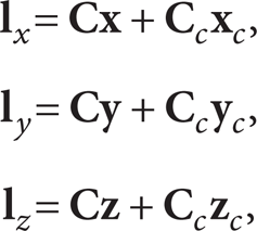
where

where

It is noted that the equilibrium equations given in (2) do not include any boundary constraints.
Let r e , r i , and r denote the number of external, internal, and total indeterminacies, respectively. The external indeterminacy is related to the boundary constraints while the internal indeterminacy is associated with the number of bars in the truss. They are defined, respectively, as follows:


where c and r b (= d(d + 1)/2) are the numbers of boundary constraints and independent rigid-body motions, respectively; n s (= n + n c ) is the total number of nodes of the truss. The number of total statically indeterminacy is given by
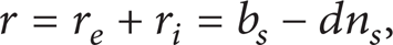
where b s (= b + c) is the sum of the number of members and boundary constraints.
Let

where
Next, as an example, consider the 3-bar planar truss supported by three hinges with two springs with the stiffness k3x and k3y as shown in Figure 1(a). Based on its free body diagram in Figure 1(b), the equilibrium equations in (7) for all nodes after moving the unknown reaction forces to the left hand side can be written as

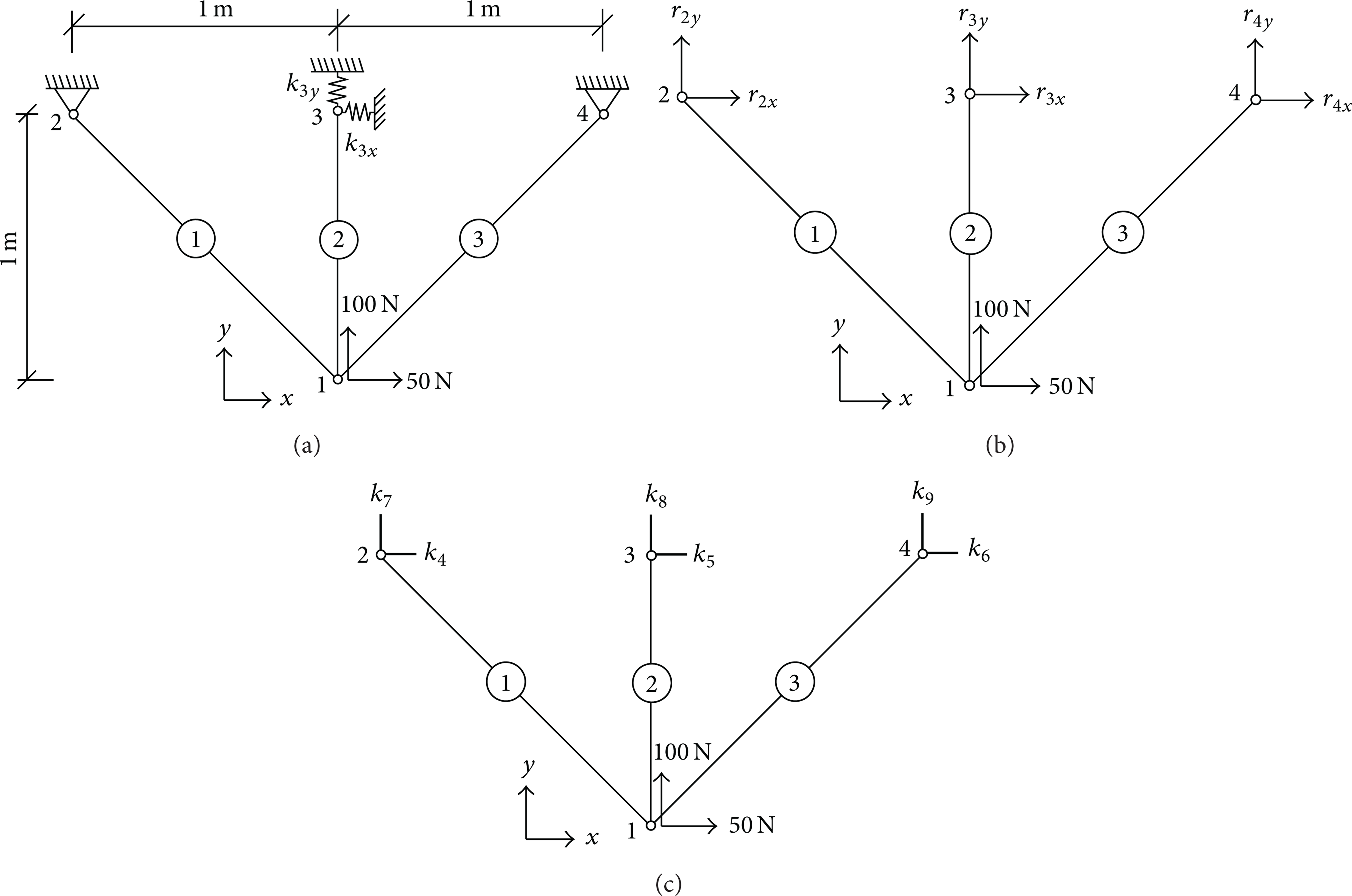
(a) A 3-bar statically indeterminate planar truss with elastic supports at node 3. (b) The free body diagram of the system in (a). (c) The equivalent free-standing model of the system in (a) with dummy members 4–9 to remove the supports.
In this study, the novel dummy members are introduced to replace the elastic supports, which enable the analysis of the trusses accounting for the flexibilities of elastic supports. Figure 1(c) shows the six novel dummy members 4–9 (which are represented by thick lines) having zero lengths (i.e., l i = 0, i = 4–9) and the stiffness k4–k9. Thus, the truss with elastic supports can be converted into the equivalent free-standing structure without supports. After implementation of structural analysis using the proposed method, the novel zero-length dummy members 4–9 will be removed to transform the nodes 2–4 back to the supports.
2.2. Kinematic Relations
The element deformation vector

where

where
The displacement-deformation relationship in the field of small displacements for the elastic conservative systems can be obtained by equating the external work and the internal strain energy as

By substituting

Based on the principle of virtual work, the above equation can be ensured to be true only if the following relation holds

Hence, the kinematic relation in (9) can be rewritten as

The expression given by (14) is the general form of the deformation-displacement relationship of the discrete system. In (14), there are r (= b
s
– dn
s
) compatibility equations which can be achieved through the elimination of the dn
s
nodal displacements from the b
s
elongations. The b
s
components of the member and reaction force vector
2.3. Compatibility Equations
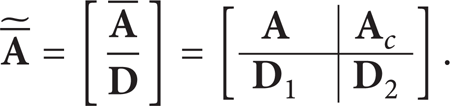
In this study, the singular value decomposition (SVD) method is adopted as an effective and numerically stable algorithm in order to extract the r compatibility conditions from (14). The SVD is performed on the general equilibrium matrix

where
The vector space bases of compatibility equations of any discrete truss structures are calculated from the transpose of the null space of the general equilibrium matrix

For any displacement vector

where

The compatibility equations in (18) assure that the elongation vector
2.4. Determination of Member Forces and Nodal Displacements
Similarly, the compatibility matrix in terms of elongations can be decomposed into two parts as

where

where

where

By substituting (19) and (21) into the left hand side of (22), the compatibility equations expressed in terms of forces are obtained as follows:

where


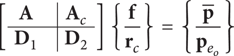
or

where
If all constrained nodes are fully rigid (i.e., there exists no spring support in the structure), all the diagonal components of

Regarding indeterminate trusses, however, it is not sufficient to conversely obtain the nodal displacements using the member elongations since the general equilibrium matrix

where

3. Implementation of Microgenetic Algorithm
Genetic algorithms (GAs) are the numerical search algorithms based on Darwin's theory of evolution and survival of the fittest. The information regarding an optimization problem, such as design variable, is coded into a genetic string known as an individual. Each of these individuals has an associated fitness value, which is determined by the objective function to be maximized or minimized. The genetic algorithms proceed by taking a population, which is comprised of different individuals with different fitness. The best individuals of the current generation are selected to produce the new generation which has better fitness by crossover and mutation operators [20]. These GAs have been shown to be capable of solving various optimization problems via some basic concepts and operators. However, it has been revealed from some research works [12, 13, 20] that the simple GA cannot solve the damage identification problems properly.
In order to acquire better identification results and high efficiency, in this study, the microgenetic algorithm (MGA) proposed by Krishnakumar [21] is used to properly identify the site and the extent of multiple damages in truss structures. The MGA utilizes a relatively smaller population size than the simple GA resulting in less computation time. The index used as the objective function to be minimized in the optimization process is demonstrated as follows:

where

where ε i d is the strain of the ith member for the damaged truss and ε i (x) is the one that can be predicted from an analytic model; ε min is the strain of the member at which the minimum axial force occurs.
Now, some basic concepts and operations of the current algorithm are introduced.
(i) Coding. The coding of variables that describe the problem are an essential characteristic of the genetic algorithm. A binary coding method is used in this study. This method is to transform variables to a binary string of specific length.
(ii) Selection Operator. The selection procedure used by current study is based on the fitness of each individual. There are number of reproduction schemes commonly used in the genetic algorithm. These include tournament selection, ranking selection, steady-state selection, greedy over selection, and proportionate reproduction. In this study, the tournament selection is used.
(iii) Crossover. Crossover is the operator that produces new individuals by exchanging some bits of a couple of randomly selected individuals. The two-point crossover is utilized since the two-point crossover performs much better among the multipoint crossover techniques [22]. In addition, the crossover rate is set as 1.0; therefore, all populations must perform a crossover operation at every generation.
(iv) Mutation and Restart Operation. There is no use of mutation operation because 1.0 crossover rate provide adequate variability. In addition, we do not use the restart operation in this study.
4. Numerical Examples
To show the accuracy and the superiority of the proposed damage detection method, two types of indeterminate truss structures are solved. Through numerical examples, all members are assumed to have the same elastic modulus E = 70 MPa and the area of cross-section A = 0.01 m2, and the initial elongation vector
4.1. 16-Bar Planar Truss
Figure 2 shows the simply supported 16-bar planar truss with the elastic springs at node 4. The truss is modelled using 16 consistent finite elements and subjected to a vertical force −1 kN acting at node 7. First, in case of the simply supported boundary condition at node 4, the flexibility matrix of the novel dummy members is zero (i.e.,

A 16-bar planar truss.
The member and reaction forces
Member and reaction forces of the 16-bar planar truss (N).

Note: SS and ES denote the simple and elastic supports, respectively.
Nodal displacements of the 16-bar planar truss (mm).

Note: SS and ES denote the simple and elastic supports, respectively.
Next, for the truss with elastic supports, the damage is introduced in element 9 by reducing its stiffness to 30% of the initial value as the first scenario. The measurement noise is simulated and entered into the analysis. The identified damage expressed in the ratio of elastic modulus reduction and the convergence history of the objective function value with generations are depicted in Figures 3 and 4, respectively. For comparison, the results from the finite element model based on the displacement method (DM) is presented together. It can be seen from Figures 3 and 4 that the two algorithms based on the force and displacement methods combined with MGA are properly achieved to the site and the extent of the hypothetical damage. The CPU time calculated for analyses by using the force and displacement methods are presented in Table 3. It is seen that the required computational time for the FM is approximately one fifth of that required by the DM, illustrating the efficiency of the FM over the DM for the analysis of planar truss structure.
Computational time for the 16-bar planar truss (sec).


Identified damage of the 16-bar planar truss for scenario 1.

Convergence history of the 16-bar planar truss for scenario 1.
In the second scenario, the damages are induced in members 5 and 13. Damaged members are assumed to have 40 and 30% of their initial stiffnesses, respectively. The identified damages and the convergence history are presented in Figures 5 and 6, respectively. It is seen that the present study detects the location and the extent of the damage with good accuracy. It can also be found in Table 3 that the computational time for the FM is significantly lower than that required by the DM.

Identified damages of the 16-bar planar truss for scenario 2.
Convergence history of the 16-bar planar truss for scenario 2.
4.2. 36-Bar Space Truss
The 36-bar space truss with 12 nodes as shown in Figure 7, subjected to horizontal forces p1x = p1y = 1 kN and vertical force p1z = – 1 kN, is considered. The truss has mixed statically indeterminacy of twelve in which six are externally statically indeterminacy, and the others are internally generated. Therefore, twelve equations of compatibility conditions are required to determine the unknown member and reaction force vector
Member and reaction forces of the 36-bar space truss (N).

Note: SS and ES denote the simple and elastic supports, respectively.
Nodal displacements of the 36-bar space truss (mm).
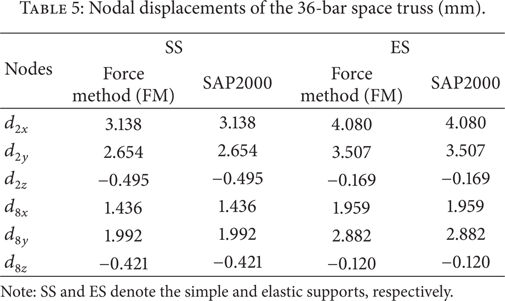
Note: SS and ES denote the simple and elastic supports, respectively.

A 36-bar space truss.
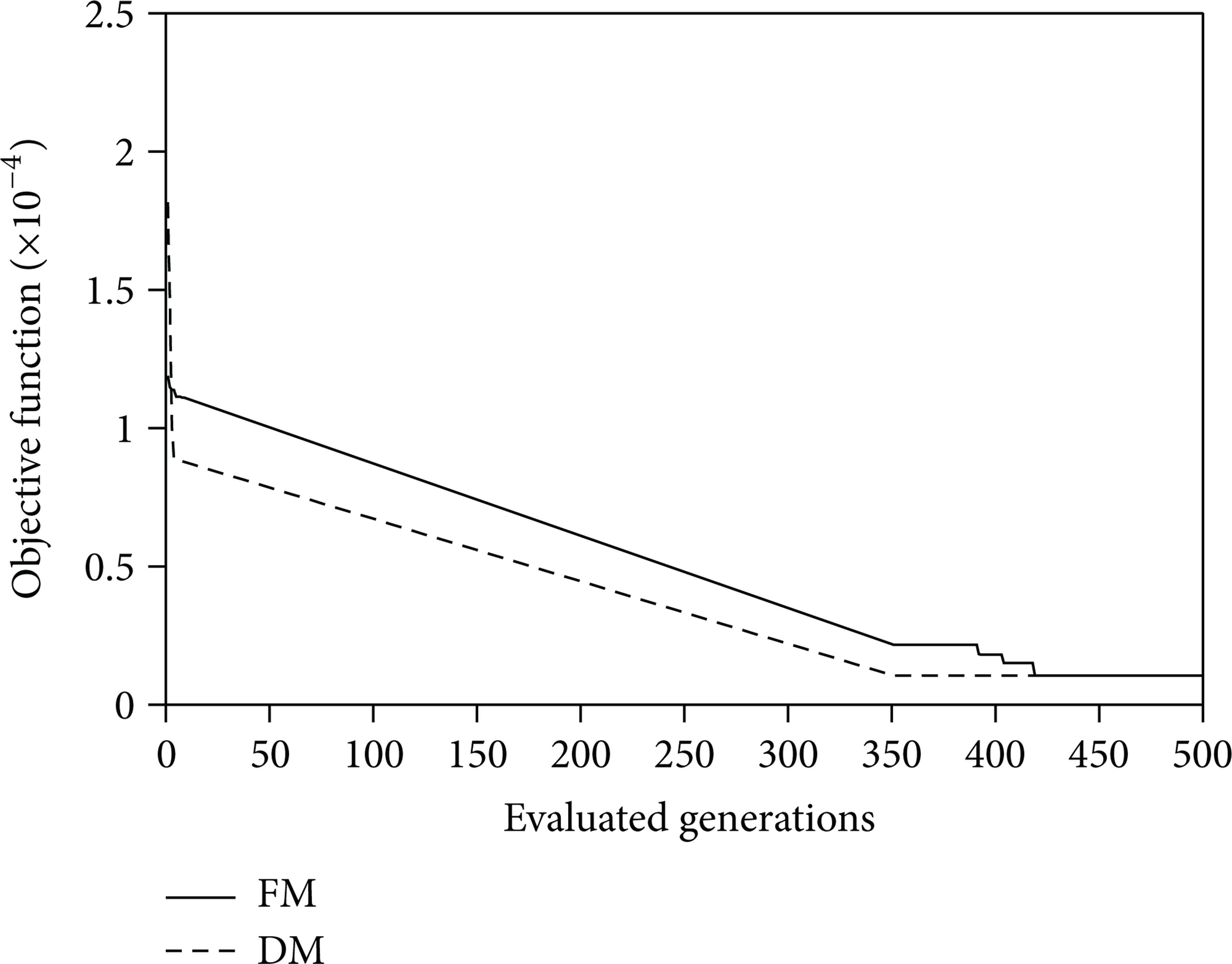
As a first damage scenario, the member 13 is damaged by reduction of its stiffness to 40% of the initial value for the truss considering elastic supports. Figures 8 and 9 show the identified damages and the convergence history, respectively, obtained from the force and displacement methods. In addition, the CPU time for analyses by two methods is given in Table 6. It is observed from Figures 8 and 9 and Table 6 that the current MGA can identify the locations as well as the extent of the damaged space truss in both cases, whereas the FM shows the superior efficiency on the CPU time required when compared with the DM as can be seen in Table 6.
Computational time for the 36-bar space truss (sec).

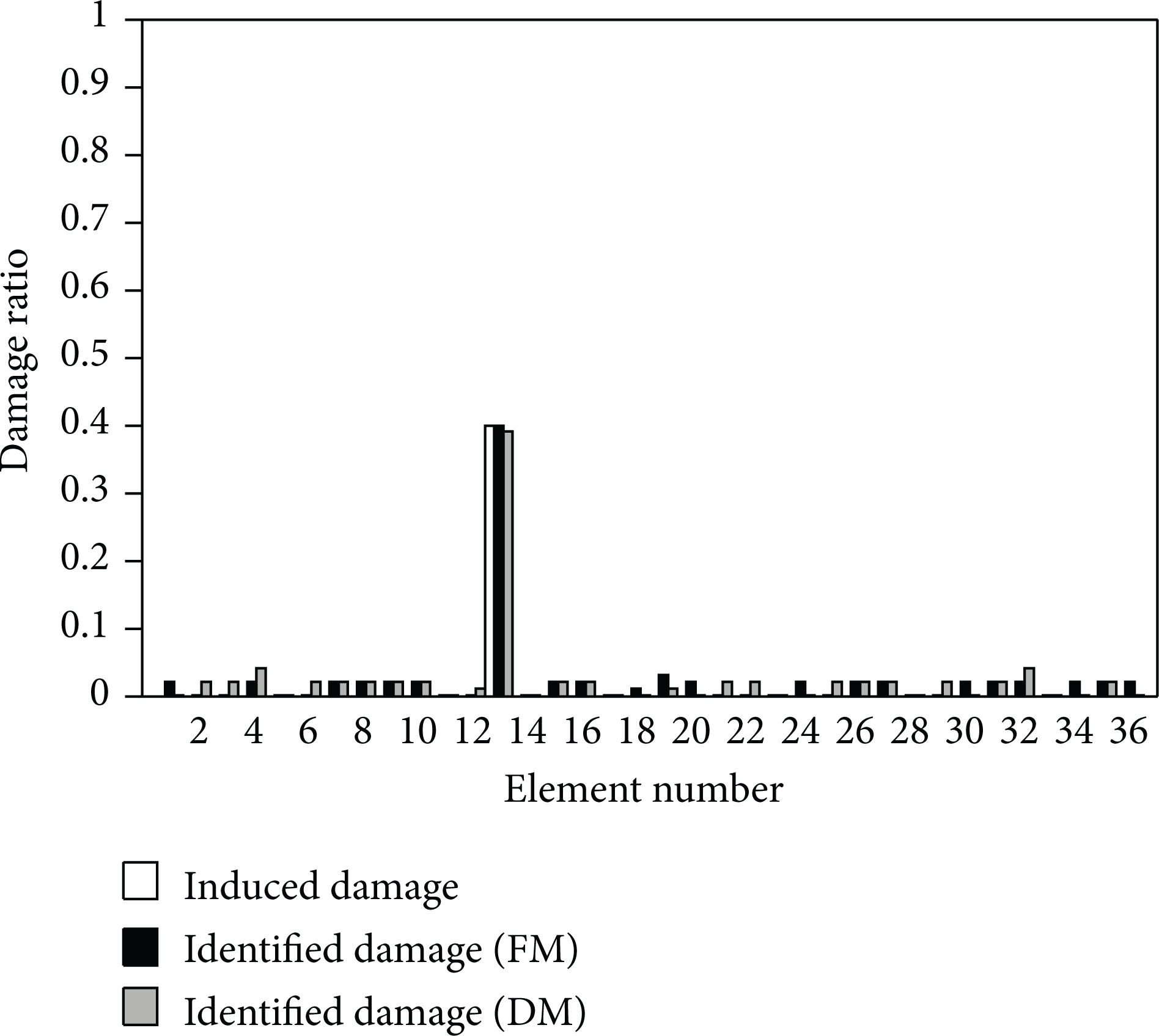
Identified damages of the 36-bar space truss for scenario 1.

Convergence history of the 36-bar space truss for scenario 1.
In our final scenario, the stiffnesses of members 1 and 21 are reduced to 30 and 50% of their initial values, respectively. The identified damages and the convergence history are plotted in Figures 10 and 11, respectively. From the results shown in Figures 10 and 11, it is observed that the present damage detection method achieves to the site and the extent of the induced damages truthfully. It can also be found from Table 6 that the computational time for the FM is significantly lower than that required by the DM, again pointing out the efficiency of the FM.
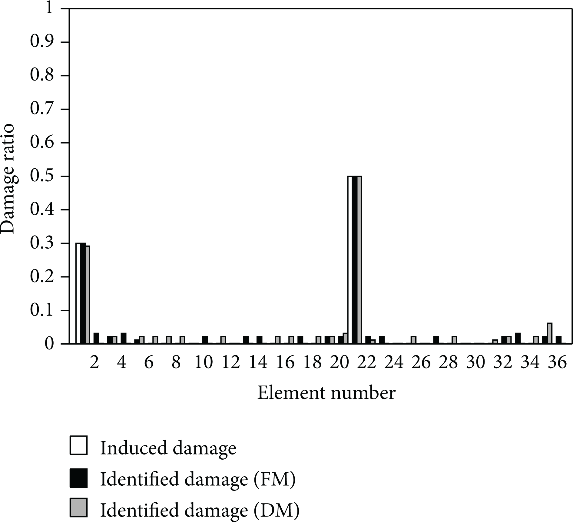
Identified damages of the 36-bar space truss for scenario 2.

Convergence history of the 36-bar space truss for scenario 2.
5. Conclusions
An efficient force method combined with the microgenetic algorithm (MGA) for identifying the location and the extent of multiple damages in the truss structures with elastic supports has been proposed. The general equilibrium equations considering the effect of elastic supports and the kinematic relations have been formulated, and the compatibility equations in terms of forces using the singular value decomposition technique are presented. Then, the optimization problem has been solved using the MGA to identify the actual damage. In order to assess the performance of the proposed method, two illustrated test examples are considered. Throughout numerical examples, the relative performance of the force and displacement methods in the damage detection analysis of the truss structures is also investigated. The numerical results indicate that the combination of the force method and MGA can provide a reliable tool to accurately identify the multiple damages of the truss structures and is computationally far more efficient than the displacement method combined with MGA.
Footnotes
Acknowledgment
The support of the research reported here by the Basic Science Research Program through the National Research Foundation of Korea (NRF) funded by the Ministry of Education, Science, and Technology (2010-0019373 and 2012R1A2A1A01007405) is gratefully acknowledged.