
Abstract
Clearance joints significantly affect the dynamic properties of deployable structures (DSs). This paper presents a spring-mass model with clearance for the study of the axial stiffness of a jointed structure. The nonlinear stiffness can be predicted by calculating the model's natural frequency which is the reciprocal of the motion period of the model. The results of the theoretical model show that the dynamic stiffness of the clearance joint increases with increases in the displacement amplitude; this finding is consistent with the experimental results. With the inclusion of sliding factors, contact friction, and impact, the established model of energy dissipation is useful for estimating the effects of joint damping on DSs. The energy dissipation model reveals the effects of joint features and excitation conditions on the dissipation of the jointed structure, that is, the excitation frequency and amplitude. Dynamic experiments were performed on jointed structures to characterize the dissipation variations. An exponentially fitting equation was developed based on the energy dissipation model and was verified through the experimental data. This formulation is more efficient than numerical integration for the calculation of the energy dissipation.
1. Introduction
Deployable structures (DSs) with joints have important applications in space missions [1–4]. The large size and volume ratio of the supporting structures require many joints in these structures. To evaluate the effect of joints on DSs, some researchers modeled the use of a link or a beam in place of a joint, but the clearance effect on the joint has not been considered. The friction and impact caused by clearance influence the dynamic properties of the jointed structure (i.e., loss of stiffness and positional accuracy and increase in damping). A significant amount of experimental and theoretical work has been conducted to analyze the effect of the clearance joints on the dynamic response of DSs in the past, and various factors have been considered, for example, contact, impact, friction, and slip.
Two main approaches are used to model a joint with clearance. The first one is a continuous method that takes into consideration the nonlinear stiffness and damping. It has been used primarily for dynamics simulation of an articulated structure. In the process of establishing a model of a jointed structure, the nonlinear force and velocity in the joint are introduced into the vibration equation [5]. The describing function method [6, 7] and the piecewise linearization method [8] are used to obtain the vibration modes of the jointed structure and the stability of the numerical solution. The second approach is a discontinuous method that is applied in mechanism system simulation. This approach takes into account impact, friction, and slip. Thus, the effects of the clearance size and the friction coefficient on the vibration of the mechanism system are assessed [9–11]. Meguro et al. [12] and Hinkle and Peterson [13] studied the arrhythmic vibration, the isolated period-doubling phenomena, and the microslip caused by clearance and roughness of the surface. Bauchau et al. [14] developed the model of unilateral contact in space systems, which took into account clearance, free-play, and friction. A more accurate joint model which introduced the nonlinear contact and the damping caused mainly by friction and impact in joints was applied to analyze the dynamics of a jointed structure.
Many experiments have been conducted on jointed structures to analyze the dynamic characteristics of the joints. The force state mapping method is one of the important ones used to study the effects of a clearance joint on the structure [15]. The force-displacement maps explicitly depict the influencing factors, such as friction force, impact force, and cubic stiffness. Ingham and Crawley reported the relationship between the clearance joint and the natural frequency of a DS based on a microdynamics experimental investigation in 2001 [16]. Peeters et al. used the nonlinear normal modes method to investigate the modal curves of a structure with a cubic spring [17]. In 2006, Yoshida [18] performed a study on the energy dissipation of a jointed cantilever in the lateral direction. Eriten et al. provided two experimental methods for mechanical joints: one is a direct fretting loop that uses the friction loop area and the ratio of the force displacement to analyze the equivalent viscous damping and the stiffness of the joint, and the other is an indirect contact resonance method that optimizes the kinetic equation of a 4-DOF system to obtain the joint stiffness and damping [19]. Because the nonlinear stiffness, the damping of the mean pressure, and the amplitude of the dynamic load are independent of the harmonic course [20, 21], the contact model is not fully equivalent.
The key problem in joint modeling is the precise evaluation of the influence of clearance and external excitation on the dissipation and the stiffness of a joint. Two types of clearances are present in one typical joint: one clearance lies in the transverse direction with the other one in the axial direction [18, 19]. The stiffnesses and the energy dissipation in transverse and axial directions of the joint are important for the jointed structure because these impact the dynamic response and precision of the structure. The focus of this paper is on the construction of an axial model of the joint that considers the relationship of both external and internal parameters with energy dissipation and stiffness. First, based on the piecewise spring-damping model, the dynamic stiffness is provided, and the effects of slip, contact, and impact on the energy dissipation are discussed. Second, an experiment was performed on a jointed structure to establish and evaluate the simplified equations of the joint dynamic stiffness and energy dissipation. The results show that the dynamic stiffness and the energy dissipation vary with the dynamic amplitude of the structure in the experiment. Therefore, the clearance is considered in the spring-mass model and the dissipation model of the joint under harmonic excitation conditions. The specific relationships of displacement, frequency, and clearance with the dissipation are obtained by fitting the integrated axial results. The changes in the tension and the compression stiffnesses of the joint under certain excitations are also analyzed. In addition, the experimental results and the theoretical model were used to verify the dynamic stiffness and dissipation energy equations.
2. Formulations
A common joint used in DSs is shown in Figure 1(a) and consists of three parts: a clevis, a pin, and a tang. As shown in Figures 1(b)–1(d), three states occur in one motion period: free-play, compression, and tension. The asymmetry of the jointed structure at different stages can cause differences between the compression and the tension stiffness of the joint. In addition to the nonlinear stiffness, the nonlinear damping is also significant in the jointed structure. It is primarily caused by the separate friction and impact in the lateral and radial directions of the joint, as shown in Figures 1(e)–1(f). This section constructs the dynamic stiffness model of the jointed structure, in which the clearance of joint, the amplitude of response, and the excitation frequency are considered for the first time. Then, the energy dissipation caused by friction, contact, and preload is estimated.
Structure with joints in different states: (a) components of the joint, (b) natural state, (c) compression state, (d) tensile state, (e) nonfriction, and (f) existing friction.
2.1. Dynamic Stiffness
Because both the contact and the noncontact states exist in a motion period, the natural frequency of the jointed structure changes with the external excitation and joint parameters. To accurately evaluate the dynamic response of the jointed structure, it is necessary to analyze the dynamic stiffness. Figure 2 shows the experimental model in which the beam, the joint, and the excitation forces are coaxial. The added mass at the end of the beam is caused by the moving component of the bearing, which is used to transmit the axial force produced by the exciter. The natural frequency of the jointed structure can be obtained by inverting the motion period that occurs when the harmonic excitation is applied at the free end.

Axial test model.
The jointed structure in the experiment can be simplified as a spring-mass model with nonlinear stiffness. This simplified model can be expressed in terms of three states (shown in Figure 3), in which m is the combined mass of the link and the moving component of the bearing used for the force transfer on the jointed structure, k0 and k1 are the respective stiffnesses of the structure in the non-contact and contact states, c is the clearance size of the joint, A is the maximum displacement of the end of the jointed structure, excluding the clearance size of the joint, and F is the excitation force.

Three states of the structure.
It is assumed that the contact force of the joint is linearly correlated to the displacement of the joint. The dynamic equation in the free-play and contact states can be expressed as

where
The displacement of the mass in the free-play state can be expressed as

where ω0 is the natural frequency of the structure in the free-play state, that is,
Based on the initial conditions t = 0, x = 0, and

where ω1 is the natural frequency of the structure in the contact stage, that is,
The time in the contact section can be expressed as

where
The natural frequency obtained by inverting the section time [18], which includes the free-play stage and the contact stage, can be expressed as

Due to the characteristics of the free-play stage, the stiffness (k0 = 0) is considered. Therefore, the natural frequency can also be expressed as
Equation (6) states that the natural frequency of the jointed structure is related to the natural frequency of the contact stage, the clearance, and the amplitude and is proportional to the static contact stiffness. The natural frequency decreases with increasing clearance size but increases with increasing displacement amplitude of the jointed structure. To investigate the effects of the amplitude on the natural frequency of the jointed structure, the displacement amplitude of forced vibration is given as

where k is the static stiffness. Therefore, F/k is the static displacement, ω is the excitation frequency, and ω n is equal to 2πf. It is assumed that it is difficult for 2ζ(ω/ω n ) and 1 – (ω/ω n )2 to reach the same order when the damping ratio ζ is small [16]. Based on the simplified equation (7) and the assumption, the dynamic stiffness k d also can be expressed as

The coefficient c
d
is equal to

2.2. Energy Dissipation
The nonlinear energy dissipation of the jointed structure is primarily caused by friction and impact. First, the total energy dissipation is calculated on the basis of the power of the excitation force F0sin (ωt), and the dissipation caused by impact and friction is evaluated based on the simplified function and integration. The relationship between the dissipation and the external excitation is then established.
Due to the absence of a guarantee for installation accuracy, the lateral pressure in the joint causes sliding friction, as shown in Figures 1 (e)–1 (f). Assuming that the lateral force is P, the energy dissipation of the sliding friction can be transformed into viscous damping. The force of the sliding friction can subsequently be expressed as
The friction exists in the lateral direction and at the contact surfaces. As shown in Figure 4, the tangential velocity vτ(t, θ) can be expressed by the velocity of the contact part v(t):
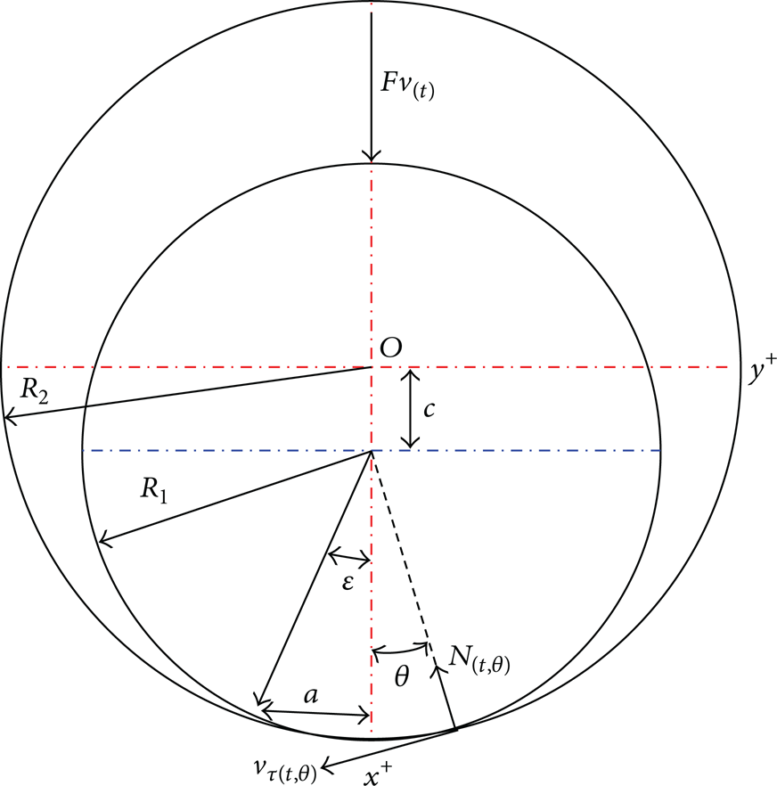
Contact model.
Due to the two contacts of the joint that occur in one cycle, the dissipation energy can be given by

where
Based on the Hertz theory, the contact force can be expressed as
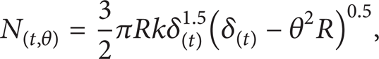
where
Next,

Therefore, the dissipation energy caused by the contact friction can be expressed as

If the velocity is not high, the energy of impact dissipation can be simplified as
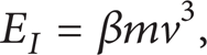
where β, m, and v are the material coefficient, the impact mass, and the velocity of motion before contact, respectively.
Thus, the total energy dissipation can be expressed as

where E
P
is the energy dissipation caused by sliding friction, which is expressed as
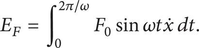
The excitation power E F can be given by
Due to the clearance of the joint, the velocity v(t) does not change with the sine function. The integral of the four sections in the energy dissipation expression must be processed in one cycle. Four factors P, ω, c, and F affect E Z . In conclusion, the numerical analysis can be evaluated based on the experimental data.
3. Experiments and Analysis
To confirm the given formula and obtain the simplified function of energy dissipation and stiffness, the corresponding dynamic experiment was conducted, as illustrated in Figure 5. One end of the beam was fixed on a base plate, and the other end was connected with a pin joint. The exciter applies a harmonic force on the jointed end which is supported by a sliding bearing. Force and displacement sensors were installed to collect data on the axial force and displacement of the jointed end.
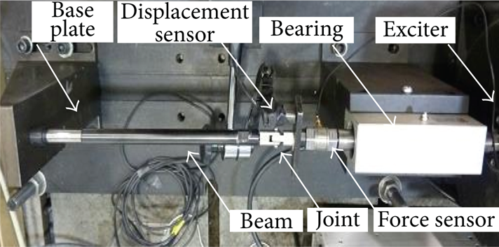
Experimental structure.
The elastic modulus of the beam is E = 2.06 × 10¹¹ Pa, and the dimensions of the jointed structure are given in Figure 6. To describe the relationships of the dissipation to the frequency, the excitation force, and the clearance, different external forces and two joints with different clearances were separately tested in the experiments.
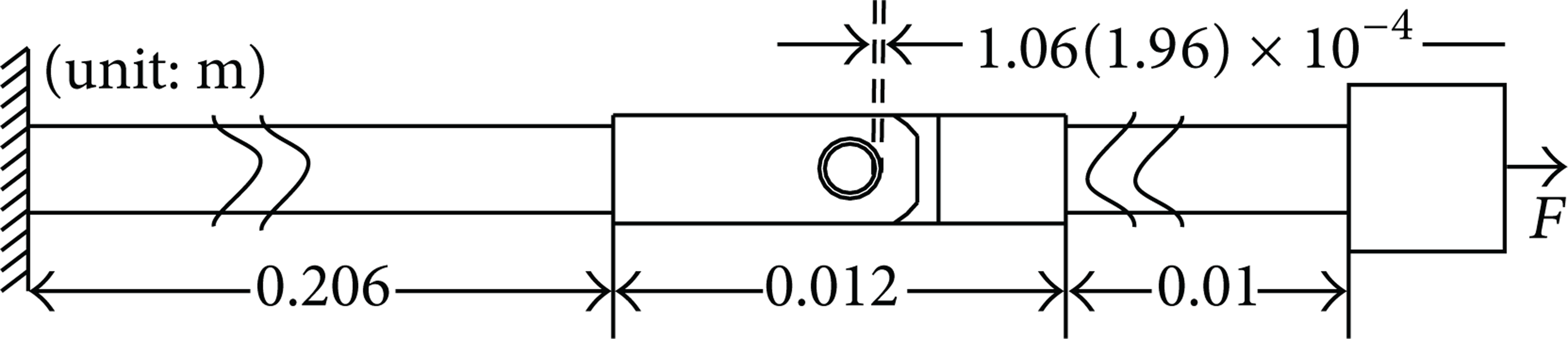
Dimensions of the structure.
The curve of the displacement response is shown in Figure 7. The AB and CD segments indicate the free-play stage. The BC and DE segments denote the compressive and tensile contact stages, respectively.
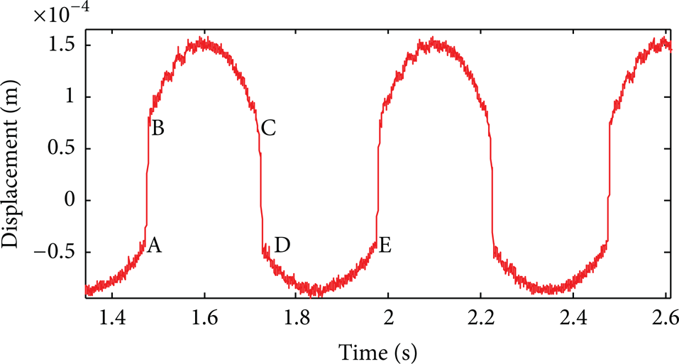
Displacement response.
3.1. Stiffness of the Structure and the Joint
3.1.1. The Stiffness of the Nonjointed Structure
The nonlinear stiffness of the jointed structure is caused by the clearance joint and the errors in the installation of the parts. Before discussing the stiffness of the clearance joint, the single link structure must be considered. It is assumed that the stiffness has a linear relationship with the excitation force and the excitation frequency. The fitting function is
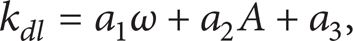
where a1 and a2 are the coefficients of the excitation frequency and displacement amplitude, respectively, and a3 is the constant term in the stiffness formula of a single link, which can be calculated by fitting the experimental data.
3.1.2. The Stiffness of the Jointed Structure
After obtaining the stiffness of the nonjointed structure, the dynamic stiffness of the jointed structure can be analyzed. In the experiment, the stiffness of the jointed structure shown in Figure 8 is related not only to the parameters of the structure but also to the excitation conditions. The experimental data can be fitted by a linear function which is the same as that shown in (19). The normalized coefficients of ω and A are shown in Figure 9.
Stiffness of the jointed structure: (a) jointed structure with the first joint (c = 0.106 mm), (b) jointed structure with the second joint (c = 0.196 mm).

Normalized coefficient of the fitted stiffness.
Figures 8 and 9 show the significant observation that the compression stiffness is larger than the tension stiffness in the same situation. In Figure 9, the proportionality coefficients for the compression stiffness of the first joint, a1 and a2, are larger than those obtained for the tension stiffness. The stiffness tendency of the second joint is the same as that obtained for the first joint. Therefore, the compression stiffness of the joint is larger than the tension stiffness. Because the coefficients are positive, the compression and tension stiffnesses increase with increasing excitation frequency and displacement.
3.1.3. The Stiffness of the Joint
Due to errors in the installation of the components, the stiffness of the non-jointed structure changes with the frequency and amplitude. Therefore, the change in the stiffness caused by installation must be discussed with respect to the calculation of the stiffness of the jointed structure. Assuming that the change in the stiffness of the beam is equal to its effects in the jointed structure, the joint stiffness in a jointed structure under constant conditions can be expressed as

where k dn and k dj are the stiffnesses of the jointed beam and the joint, respectively, and k dn = b1ω + b2A + b3.
The dynamic stiffness k
dj
can exactly reflect the nonlinear characteristic caused by the joint. Figure 10 shows the change in k
dj
which is induced by the excitation frequency and the amplitude. It is clear that the stiffness increases with increasing displacement amplitude and decreases with increasing excitation frequency at the beginning. However, there is slight increase in k
dj
when the frequency is increased. Because when ω increases to

Dynamic stiffness of the joints: (a) tension state of the first joint, (b) compressive state of the first joint, (c) tensile state of the second joint, and (d) compressive state of the second joint.
3.2. Dissipation of the Jointed Structure
The energy dissipation increases with increasing excitation frequency and deformation, as shown in (16). The variation in the friction and impact dissipation corresponds to the external energy inputted. Therefore, the energy dissipation can be expressed as a function of the displacement amplitude. Based on the analytical and experimental results obtained with the jointed structure, the total energy dissipation changes with variations in the clearance size, the displacement amplitude, and the excitation frequency, as shown in Figure 11. This trend is similar to an exponential function which can be expressed as

Relationship between displacement amplitude and energy dissipation: (a) the first joint, (b) the second joint.
The fitting results show that the parameters c1 and c2 change together with the clearance size and frequency. The coefficients of the function can be obtained by fitting the integrated results of the experimental data.
The coefficients indicate that the energy dissipation of the jointed structure decreases with increasing clearance size. The energy dissipation can be expressed as

4. Discussion
For ensuring the effectiveness of the dynamic stiffness calculated by (9), the magnification coefficient of the joint stiffness shown in Figure 12 was compared with the experimental result shown in Figure 8.

Inverse ratio of the structure stiffness to the displacement.
Obviously, the dynamic stiffness coefficient c d increases with increases in the displacement amplitude, and remains stable at large deformations. Therefore, the stiffness of the jointed structure exhibits more significant changes than the non-jointed structure. In the experiment, the stiffness of the jointed structure increases with increasing excitation amplitude and the increase rate declines at large excitation amplitudes. The analytical results are in agreement with the experimental results. The experimental data does not directly reflect the impact of the joint stiffness on the jointed structure stiffness. However, the calculation result of the dynamic stiffness of the joint based on the experimental data shows a clear trend. The dynamic stiffness of the joint in the experiment decreases with increasing excitation frequency at the beginning, which agrees with the result of the analysis. By comparing the analytical result with the experimental result; the correctness of the analytical method is proved.
To evaluate the energy dissipation equation, a comparison of the experimental and the analytical results was conducted. The calculated results from (22) agree with the experimental results shown in Figure 13.

Energy dissipation under different parameters: (a) energy dissipation at different clearances, (b) the energy dissipation of the first joint, and (c) the energy dissipation of the second joint.
As shown in Figure 13, it is clear that the function expressed by (22) can provide accurate energy dissipation, which exhibits an exponential relationship with deformation, frequency, and clearance. The dissipation increases with increases in the excitation frequency and the deformation amplitude of the structure and with decreases in the clearance.
5. Concluding Remarks
In this paper, a spring-mass model with clearance was established to measure the joint stiffness. The calculated results of this model are consistent with those from the experiment. The formula for the natural frequency of the jointed structure shows that the natural frequency decreases with increasing joint clearance but increases with increasing amplitude. The relationships between the dynamic stiffness of the joint and the natural frequency, the excitation frequency, and the response amplitude were established.
The integral model for the calculation of the energy dissipation which considers the effects of the sliding friction, the contact friction, and the impact in the joint was presented. Based on the integral model, the dissipation function of the jointed structure can be used to estimate the effects of the joint clearance, the external excitation frequency, and the amplitude on the fixed jointed structure.
The results of the experiments on non-jointed and jointed structures were compared to study the stiffness and the dissipation of the clearance joint. The analytical and experimental results for the nonlinear stiffness are consistent. The dissipation model was verified through the jointed experimental results. This function is more efficient than numerical analysis for the estimation of the dissipation of a jointed structure. The dissipation and dynamic stiffness can be applied to analyze the dynamic characteristics of jointed structures.
Footnotes
Acknowledgments
The authors acknowledge support from the “111 Project” (Grant no. B07018) and the Natural Science Foundation of China (Projects no. 50935002 and no. 11002039).