
Abstract
In order to improve the efficiency of stainless steel stamping multistage pump, quadratic regression orthogonal test, hydraulic design, and computational fluid dynamics (CFD) are used to analyze the effect of pump geometric parameters. Sixteen impellers are designed based on the quadratic regression orthogonal test, which have three factors including impeller outlet slope, impeller blade outlet stagger angle, and impeller blade outlet width. Through quadratic regression equation, the function relationship between efficiency values and three factors is established. The optimal combination of geometric parameters is found through the analysis of the regression equation. To further study the influence of blade thickness on the performance of multistage pump, numerical simulations of multistage pump with different blade thicknesses are carried out. The influence law of blade thickness on pump performance is built from the external characteristics and internal flow field. In conclusion, with the increase of blade thickness, the best efficiency point of the pump shifts to the small flow rate direction, and the vortex regions inside the pump at rated flow gradually increase, which is the main reason that pump efficiency decreases along with the increase of the blade thickness at rated flow.
1. Introduction
Most pumps in the past were manufactured by casting process. Traditional casting pump is made by some complex manufacturing processes such as moulding and mechanical processing. These processes will consume lots of power and material and emit a huge amount of toxic gas. Also in the mass production process of small pump, the dimensional accuracy and surface roughness cannot be guaranteed due to the limitation of casting process. That is because the impeller channel in small pump is always long and narrow, and it is difficult to produce small impeller through traditional casting process. Combined with structural characteristics of pump, it is completely feasible to adopt stamping process in the production of pump. Therefore, stainless steel stamping multistage pump emerges. Stainless steel multistage pump is a new-type centrifugal pump. It is clean, healthy, and energy saving, and more and more people prefer to use stainless steel pump. Currently, there are two problems of stamping stainless steel multistage pump. Firstly, the efficiency of stainless steel multistage pump in many pump factories is not very high, due to the fact that stainless steel multistage pump emerges in recent years. Secondly, the single head of stainless steel multistage pump is very low, resulting in the axial length of stainless steel multistage pump which is very large, which increases the cost of production. Therefore, because of expensive cost of stamping mold, it is very necessary to provide excellent hydraulic mode for stainless steel stamping multistage pump [1, 2].
Orthogonal test is a common optimization method to study a target with multiple factors and levels [3, 4]. It has been widely used in the design of pump. Yuan (1997) made an in-depth study for the relation between geometric parameters and performance of pump without overload and gave a set of functional theory and design method by using an L9 (27) orthogonal test [5]. Using the orthogonal test design method, Wang et al. (2010) made a deep research which described the influence of the main geometric parameters of impeller on the deep well pump characteristics [6]. Zhou et al. (2013) researched the impeller and found the key factors affecting the performance of impeller by making an orthogonal test [7]. Therefore, orthogonal test method is a mature method of optimization, which is very suitable for the pump design.
Orthogonal test can use less number of tests to obtain better results, but optimization program obtained by orthogonal test can only be limited to the given level, but it is not be the optimal solution within the test range. Meanwhile, regression analysis is an effective method of data analysis. Through the established regression equation, the experimental results can be predicted and optimized. However, regression analysis does not involve to the requirement of experimental design. Combined with the advantages of two methods, quadratic regression orthogonal test method appears. Quadratic regression orthogonal test methods are also response surface methods, which use quadratic regression equation to fit the function relationship between each factor and response value [8]. Through the analysis of the regression equation, the optimal combination of geometric parameters can be found. It is a statistical method to solve multivariable problems. In this paper, quadratic regression orthogonal test method is used to improve the efficiency of pump with three factors including impeller outlet slope, impeller blade outlet stagger angle, and impeller blade outlet width.
2. Hydraulic Design
2.1. Hydraulic Design of Impeller
100XQJ8 stainless steel stamping multistage well pump is selected in this paper, and the basic design parameters are as follows: rated flow Q des = 8 m3/h, single-stage head H = 4.5 m, and rotation speed n = 2850 r/min.
In view of the structural condition that the outer diameter of well pump is limited by well diameter, Lu et al. proposed a new design method of multistage well pump, “the impeller maximal diameter design method” [9], which expands the front shroud of impeller to the edge of pump wall and makes the impeller diameter achieve maximum value while well diameter is invariable. The impeller is in coordination with the return guide vane, which can shorten the axial length of pump to the minimum.
In the design of the previous pump, the impeller diameter is calculated based on the requirements of pump performance, but the impeller maximal diameter design method only provides rated flow at the maximum efficiency point and will not provide rated single-stage head, which aims that the single-stage head is as high as possible, thereby reducing the series and costs of pump. In this paper, the new design method is used completely. The front shroud diameter of impeller is 79.5 mm, which is equal to the diameter of the pump casing. The clearance is guaranteed by tolerance and the outlet of impeller is skewed, which is shown in Figure 1. After determining the front shroud diameter of impeller, according to speed coefficient method, the other structural parameters of impeller can be designed as follows: impeller blade number Z1 = 9, impeller shaft diameter d1 = 12.5 mm, impeller hub diameter d h = 17 mm, impeller inlet diameter D j = 39.4 mm, impeller blade thickness δ = 1.5 mm, impeller blade inlet stagger angle β1 = 35°, and wrap angle φ = 100°. The shroud, hub, and blade form an integral impeller after welding process. In order to reduce the cost, the cylindrical blade is adopted.
Impeller.
2.2. Hydraulic Design of Return Diffuser
In this paper, a common cylindrical return diffuser is used, which have the lower production cost and smaller axial length.
The blade shape of cylindrical return diffuser is almost the same as the cylindrical impeller. Firstly, the blade inlet stagger angle and outlet stagger angle are calculated, and then the inlet and outlet of return diffuser are connected smoothly by two circular arcs. The main structural parameters of return diffuser are as follows: blade inlet stagger angle β3 = 25°, blade outlet stagger angle β4 = 90°, blade number Z2 = 8, blade inlet width B3 = 6.2 mm, blade inlet diameter D5 = 75 mm and blade inlet diameter D6 = 29 mm, which is shown in Figure 2.

Return diffuser.
3. Quadratic Regression Orthogonal Test
3.1. Test Factors
According to the previous design experience, impeller outlet slope θ, blade outlet stagger angle β2, and blade outlet width b2 are three important factors affecting the efficiency of stainless steel stamping multistage well pump. In this study, response surface method was adopted to analyze the relationships between these three factors β2 (15°–40°), b2 (3 mm–8 mm), and θ (0°–45°) and test indicators (efficiency) within the range.
3.2. Level Code of Factors
Star arm length formula is as follow:
In the formula, r star arm length; m c the number of two level test; m the number of factors; m0 the number of zero level test.
As the number of factors is equal to 3, if the number of zero level test takes 2, the number of two level test m c = 23 = 8. According to formula (1), star arm length r = 1.287. Because the range of factor x1 is from 15° to 40°, it can be calculated that zero level x10 = 27.5° and changing interval Δ1 = (40 – 27.5)/1.287 = 9.71. So the up level x12 = 27.5 + 9.71 = 37.21° and the down level x22 = 27.5 – 9.71 = 17.79°. Similarly, the codes of blade outlet width b2 and impeller outlet slope θ are also calculated as shown in Table 1.
Factors and levels.
3.3. Orthogonal Combination Design
As the number of factors is equal to 3, the orthogonal table L8(23) is selected. Then, the number of zero level test takes 2, the number of two level test m c = 23 = 8, and the number of star test 2m = 6, which are shown in Table 2. Finally, 16 groups of hydraulic model are designed through the last calculation value of other geometrical factors.
Test programs.

4. Numerical Simulation and Results Analysis
4.1. Computational Domain
Sixteen groups of impellers which are made from prototype manufacturing will make high cost and a large amount of time. In combination, current computational fluid dynamics (CFD) technology has been able to reflect truly the internal flow field of centrifugal pumps and predict accurately the head, efficiency, and shaft power of pumps at rated flow. Therefore, by using flow analysis results, we can forecast preliminarily whether the pump performances meet the design requirements [10–12].
Compared with single-stage pump, the structure of stainless steel stamping multistage well pump is more complex and its flow characteristics are different [13, 14]. The flow in the first impeller inlet of multistage well pump is usually irrotational while being rotational in the other impeller inlet. Because the flow after the first stage is similar, two-stage model is selected and consists of inlet section, two impellers, two chambers, two return diffusers, and outlet section. The solid models are, respectively, established and assembled together in Pro/E, which is shown in Figure 3.

Computational domain. 1: inlet section, 2: impeller, 3: chamber water, 4: return diffuser, 5: outlet section.
4.2. Model Mesh
This mesh generation is completed by using special preprocessing software—Gambit, which is considered to be one of the best commercial CFD software preprocessors [9, 10]. In the whole modes unstructured tetrahedral mesh is used and the mesh of impeller and return diffuser are shown in Figure 4.

Mesh of impeller and return diffuser.
4.3. Results and Analysis
Efficiency of these 16 groups pumps is obtained by numerical simulation, and it forms quadratic regression equation of efficiency on β2, b2, and θ, namely, y = f(x1, x2, x3). Although this regression equation is nonlinear, if x1x2, x1x3, x2x3, x12, x22, and x32 were regarded as six variables respectively, the above three-variable quadratic regression equation becomes nine-variable linear equation. Regression coefficients can be determined using “Regression” tool in Excel, as well as the significance of the regression equation. This method can not only greatly reduce the workload but also improve the accuracy of the calculation.
Firstly, the raw data are handled properly. Values of x1x2, x1x3, x2x3, x12, x22, and x32 need to be calculated, which are shown in Table 3.
Regression analysis of raw data.

Enter the regression dialog box, fill in the content, and the results are as follows.
Partial regression coefficients are b i : −88.13, 2.71, 31.95, 0.75, −0.29, −0.0018, −0.035, −0.015, −1.78, and −0.008.
Therefore, the expression of regression equation is as follows:
According to extreme conditions, we have

Solve (4):


Results are as follows: x1 = 23.2, x2 = 6.8, and x3 = 29.4.
When β2 = 23.2°, b2 = 6.8 mm, and θ = 29.4°, the theoretical prediction of the efficiency of pump reaches 62.8% according to formula (2). Modeling in accordance with the above geometric parameters, the numerical simulation value of efficiency is equal to 62.98%, whose error is less than 1% compared with the theoretical prediction. It proves that the optimization of stainless steel stamping multistage well pump is feasible using response surface methodology.
5. Influence of Impeller Blade Thickness on Stainless Steel Stamping Multistage Well Pump
The factors of quadratic regression orthogonal test can only be continuous variables, while the thickness of stainless steel can only be a series of discrete points according to national standard. So impeller blade thickness is not selected as test factor and 1.5 mm is selected as a common value of impeller blade thickness in the quadratic regression orthogonal test. However, the blade of stainless steel pump can be much thinner than cast-iron pump, which makes the design technology of traditional casting pumps not applicable to stainless steel pump. Therefore, it is necessary to study the influence law of impeller blade thickness on stainless steel pump.
5.1. Impeller Model with Different Blade Thicknesses
Based on the optimal model, the other geometric parameters of impeller are invariable and the impellers with different blade thicknesses (δ = 0.5 mm, δ = 1.0 mm, δ = 1.5 mm, δ = 2.0 mm, and δ = 2.5 mm) are established, as shown in Figure 5.

Five impeller models with different blade thicknesses.
5.2. External Characteristic
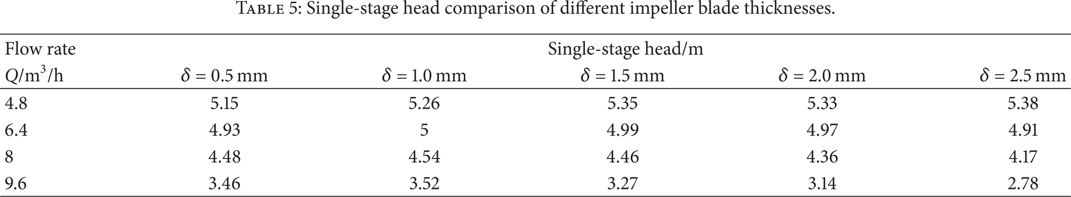
Five impeller models are simulated by using CFD, and the efficiency and single-stage head are obtained, as summarized in Tables 4 and 5. Firstly, the change of impeller blade thickness impacts on efficiency and head significantly, and the head curve becomes steeper with the increase of impeller blade thickness. At the rated flow and large flow rate, the efficiency and single-stage head decrease as the increase of impeller blade thickness while being at small flow rate, which indicates that the best efficiency point of the pump shifts to the small flow direction with the increase of impeller blade thickness. The efficiency and head change a little at rated flow when impeller blade thickness changes from 0.5 mm to 1.5 mm. If it exceeds 1.5 mm, with the increase of thickness, the efficiency and head decrease rapidly. This means that the thickness should be limited within a reasonable range. In this paper, in view of the pump performance and impeller strength, 1.5 mm is selected as the impeller blade thickness.
Efficiency comparison of different impeller blade thicknesses.

Single-stage head comparison of different impeller blade thicknesses.
5.3. Internal Flow Field
In order to explore how impeller blade thickness influences the internal flow of pump, the flow field of the middle cross section in the whole flow passage is compared. Affected by the limited length, the turbulent kinetic energy distribution and velocity distribution of the pump with three different blade thicknesses at rated flow are analyzed.
Turbulent kinetic energy reflects the extent of turbulent fluctuation, and its size and spatial nonuniformity indicate the size and occurrence scope of pulsating diffusion to a certain extent. Figure 6 shows the turbulent kinetic energy distribution of the liquid in the pump with three different blade thicknesses. It can be seen that the turbulent kinetic energy in the inlet of impeller and return diffuser is relatively big, indicating thatthere is a certain liquid impact, vortex or backflow in these places. Moreover, the turbulent kinetic energy of the liquid in the pump increases gradually with the increase of impeller blade thickness, especially when the impeller blade thickness is 2.5 mm. Therefore, impeller blade thickness should be limited in a certain range to improve the efficiency of pump at rated flow.
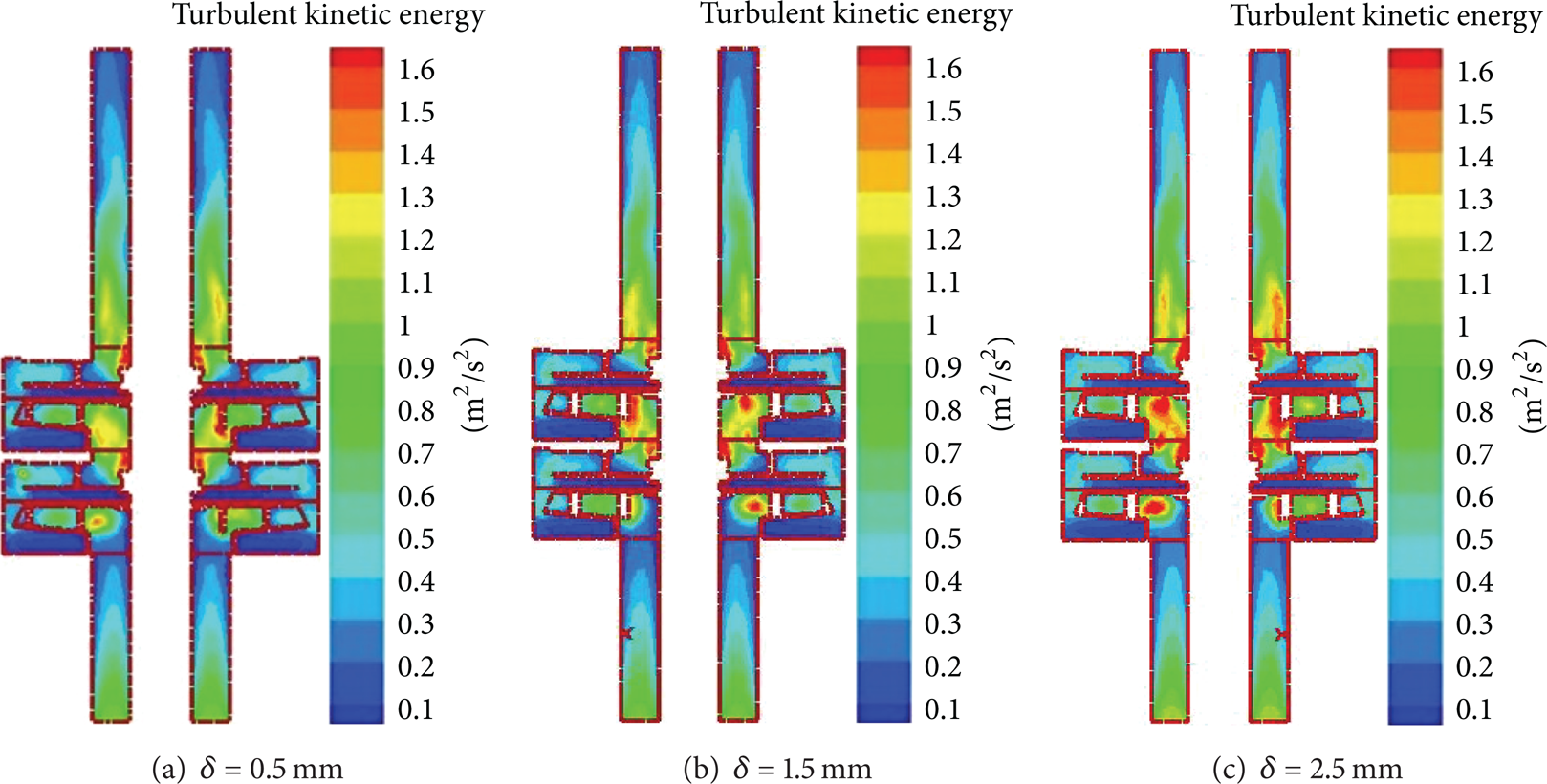
Turbulent kinetic energy distribution in the middle cross section at rated flow.
Figure 7 shows the velocity distribution in the pump cross section with three different blade thicknesses. In the whole flow process, there is a certain vortex or backflow in the former pump chamber and impeller export. Due to the vortex in the front pump chamber is equivalent to a group of stagnant water, it cannot cause too much hydraulic losses, which is also confirmed by the small turbulent kinetic energy in the front pump chamber from Figure 6. However, the backflow in the impeller export will hamper the flow of liquid from the impeller, thereby generating large energy losses and turbulent kinetic energy. In addition, with the increase of blade thickness, the best efficiency point of the pump shifts to the small flow direction, and the vortex regions inside the pump at rated flow gradually increase, which is the main reason that pump efficiency decreases along with the increase of the blade thickness at rated flow.

Velocity distribution of the liquid in the middle cross section at rated flow.
6. Experimental Analysis of Optimal Model
In order to verify the accuracy of numerical calculation and validity of quadratic in the regression orthogonal test, the optimal model (β2 = 23.2°, b2 = 6.8 mm, θ = 29.4°, and δ = 1.5 mm) is manufactured and tested in the multistage well pump performance platform which is shown in Figure 8. The comparisons of the predicted performance and experimental performance are shown in Figure 9. The simulation value and test value are consistent with fairly well at design flow rate and large flow rate, and the variance is less than 1%. At small flow rate, the liquid in the impeller and return diffuser easily produces flow separation, and there are some differences between actual flow and simulating flow, resulting in more than 2% deviation between simulation values and test values.

Test ring of multistage well pump.

Comparison between simulation and experimental value.
The pump efficiency reaches 61.36% at rated flow, and single-stage head reaches 4.85 m. Comparing the pump standard of China (GB/T 2816—2002), the requirement efficiency of the pump 100QJ8 is 53%. Therefore, the optimal design of the stainless steel stamping multistage well pump has an obvious performance improvement.
7. Conclusions
Impeller outlet slope θ, blade outlet stagger angle β2, and blade outlet width b2 have the obvious effect on the pump efficiency. The function relationship between pump efficiency and three parameters was fitted by using quadratic regression equation. Through the analysis of the regression equation, the optimal combination of geometric parameters could be found.
At rated flow and large flow rate, the efficiency and single-stage head decrease with the increase of impeller blade thickness, but at small flow rate this relationship is on the contrary. Meanwhile, the pump best efficiency point shifts to the small flow direction with the increase of impeller blade thickness.
There is an acceptable agreement between test value and simulation value, which proves that numerical simulation in the whole flow field can accurately guide the design of the stainless steel stamping multistage well pump.
Footnotes
Notation
Conflict of Interests
The authors declare that there is no conflict of interests regarding the publication of this paper.
Acknowledgments
This research was supported by the Priority Academic Program Development of Jiangsu Higher Education Institutions, the National Natural Science Foundation of China (Grant nos. 51109093 and 51279069), the National Natural Science Foundation of Jiangsu Province (Grant no. BK20131256), the Graduate Innovation Project of Jiangsu Province (CXLX12_0642), and the National Science and Technology Support Project (2011BAF14B01).