
Abstract
Due to the advantages of its compact structure and high operation accuracy, the six degrees of freedom (6-DOF) parallel platform has been widely used as a carrier of medical rehabilitation devices. Fuzzy adaptive algorithm does not depend on the mathematical model of controlled object, which possesses good nonlinear characteristics. Those entire features make it an effective method to control such complex and coupling platforms. To facilitate the application of robotics in lower limb rehabilitation fields, a robotic system in practical environment was established based on kinematics modeling of the 6-DOF Stewart-based platform. In order to improve the velocity tracking accuracy, this paper proposed a closed-loop control strategy based on fuzzy adaptive algorithm. The velocity feedback information was utilized to modify the PID parameters adaptively in realtime through fuzzy inference units. Several experiments in practical environment were conducted, and the results demonstrated that the proposed algorithm could effectively reduce the speed jitter, enhance the position and velocity tracking precision of the robot, and the reliability and robustness of the system could also be ensured.
1. Introduction
With the tendency of aging society, there is a considerable increase in the needs of health care and rehabilitation, especially among elderly and disabled people, which are supposed to recover or compensate patients' functional capabilities, enable them to be independent, and improve their living qualities [1, 2]. Applying assistive robotics to rehabilitation can not only release rehabilitation physicians from the heavy training missions but also provide a platform to evaluate the convalescence results of the patients by analyzing the data recorded during the training process. Nowadays, there exists a wide variety of medical robots that differ in mechanical structures, control strategies, or even the target users. Particularly in recent years, due to the rapid development of biological techniques and intelligent control methods, various rehabilitation robots including those for both upper and lower limbs have been developed by many institutions [3]. In terms of lower limb rehabilitation, the HAL in Japan is a typical lower limb rehabilitation robot that implements active control for patients, making people able to move the actuators by mapping the EMG signals to the joint angles of lower extremity [4]. Moreover, the NeXOS in England is a novel robotic prototype which combines engineering experience with medical theory [5], and it is used for hip and knee joint exercise training on various operating modes. The mechanical design is the basis of robot-assisted rehabilitation system, which should comply with the disciplines of being simple, lightweight, and to control [6]. Meanwhile, the 6-DOF parallel robot is probably a feasible solution in the lower limb rehabilitation fields, for its simple structure and superior adaptability, enabling the robot's movement of range, and the rehabilitation parameters can be adaptable to different patients.
The Stewart platform is a kind of typical 6-DOF parallel robot. As a multi-input multioutput (MIMO) and nonlinear system, the 6-DOF parallel robot's position and orientation are the results of six actuators' interaction and coordination with each other, involving serious nonlinear coupling interference [7]. In order to improve the trajectory tracking performance, many intelligent control methods for parallel robots have been proposed. Lee et al. presented a linear H∞ robust controller based on computed torque, to overcome the adverse effects caused by parameter variations and load disturbances [8]. However, this approach is complex and the calculation time is too long, so it is not suitable for real-time control applications. A simplified robot model and cerebella model articulation controller (CMAC) with neural network were introduced by Wang et al. [9] to reduce the coupling effects between the branches and achieve higher control accuracy, but this requires a huge amount of training and learning time [10]. Besides, many pieces ofliterature tend to propose control approaches based on simulation but without verifying them through specific experiments in practical environment [11, 12]. Nowadays, there are still not enough research papers on velocity control, because the parallel robot contains multiple kinematic chains, and the dynamic model is very difficult to establish [13]. Meanwhile, due to its inherent advantages of inference, as well as possessing good robustness and nonlinear characteristics, fuzzy adaptive method is a potentially effective approach to control such objectives with time-varying and nonlinear parameters.
Currently, many research papers on fuzzy adaptive algorithm are obtained from theoretical analysis or simulation experiments, while applying such approaches for actual parallel robot is not very common [14]. In this paper, we propose a practical fuzzy PID controller based on the combination of fuzzy adaptive algorithm and the PID controller, and the designed strategy is applied to control the parallel robot in actual environment for medical purpose. In this context, the real-time feedback information of the platform is utilized to complete the correction and optimization of the PID controller based on fuzzy inference. This paper is organized as follows: Section 2 presents a multi-DOF parallel robot and its kinematic model, and a velocity tracking control strategy based on fuzzy PID adaptive algorithm is proposed in Section 3. Several experiments based on the real robot were conducted in Section 4. Finally, conclusion and future works are drawn in Section 5.
2. Modeling of 6-DOF Parallel Robot
The Stewart platform is a parallel robot whose operation is based on the simultaneous movement of its six branches. Different from traditional serial robots, Stewart parallel platform consists of a moveable upper platform, a fixed base platform, and six actuators. The upper platform and the base platform are connected by linkages, where spherical and Hooke joints are adopted between these linkages and platforms. A model of the 6-DOF parallel robot is established in ADAMS (as shown in Figure 1(a)), where the servomotor is equipped to drive the electric cylinders, and thus we can achieve the desired trajectory of the moving platform. In order to control such parallel platform effectively, its kinematic model has to be established.
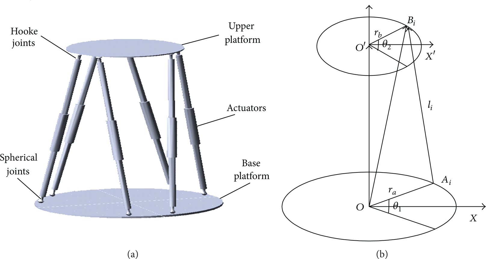
Model of the parallel robot: (a) mechanical structure (b) victor analysis diagram.
2.1. Kinematics of the Parallel Robot
The kinematics problems of parallel robot can be divided into the forward kinematics and inverse kinematics. The forward kinematics means to calculate the position of the end effectors when the joint coordinates of six legs are known, while the inverse kinematics is opposite. For parallel manipulators, the inverse kinematics is much easier to be calculated than the forward one [15, 16]. The reason is that the forward kinematic model contains highly nonlinear parameters and high-order equations need to be solved. The most widely used methods for this problem include analytical and numerical solutions. However, the mathematical model of analytical approach is very complex, while the numerical approach is also unsuitable as its convergence will be largely influenced by the parameters' initial value. Therefore, it is difficult to calculate the forward problem in practical applications. On the other hand, if the desired translational and rotational position of the upper platform is given, the inverse kinematics could be used to transform the desired trajectory into the displacement of each actuator, and thus we are able to control the respective joints instead of the moving platform. Therefore, the inverse kinematic model is our concern in this paper. The geometric model of platform is illustrated in Figure 1(b), where the radius of the upper platform is defined as r b and the angle is θ2; likewise, the fixed platforms are defined as r a and θ1, respectively.
Define the coordinate vector of the upper platform center in an inertial coordinate as (1), while the position and orientation vector of the moving platform as (2),
The coordinate of the upper platform joint B i can be calculated as
where
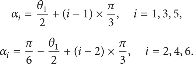
Similarly, the coordinate of the fixed platform jointA i can be expressed as

where
The basic movements of upper platform include rotation and translation, and the inverse kinematics can be calculated by using matrix tools, which can be defined as
And rotation matrix of the 6-DOF parallel robot can be obtained as

We can now give the expression of the length vector l i of leg i as the difference between B i and A i .
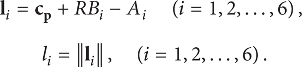
Then the relationship between displacement of each leg
2.2. Prototype of the Robotic Control System
The designed prototype of 6-DOF parallel robot control system is shown in Figure 2. The parallel robot is equipped with six actuated joints, and each joint is separately driven by an AC servo motor, which works at the position closed-loop mode. The feedback information of each actuator includes the position and velocity that can be obtained from photoelectric encoders, which are coaxially integrated in the motor. In this system, the control software firstly develops the desired trajectory of the upper platform according to the users' requirement, and then the system will transform the planned trajectory into the displacement of each leg through inverse kinematics. As indicated in Figure 2, the robot control system contains six independent control loops, where feedback signals are utilized to be compared with the expected values. According to the calculated errors between these desired and actual data in each loop, the system will generate corresponding control commands for each actuator so as to realize the position and velocity tracking control of the entire system.
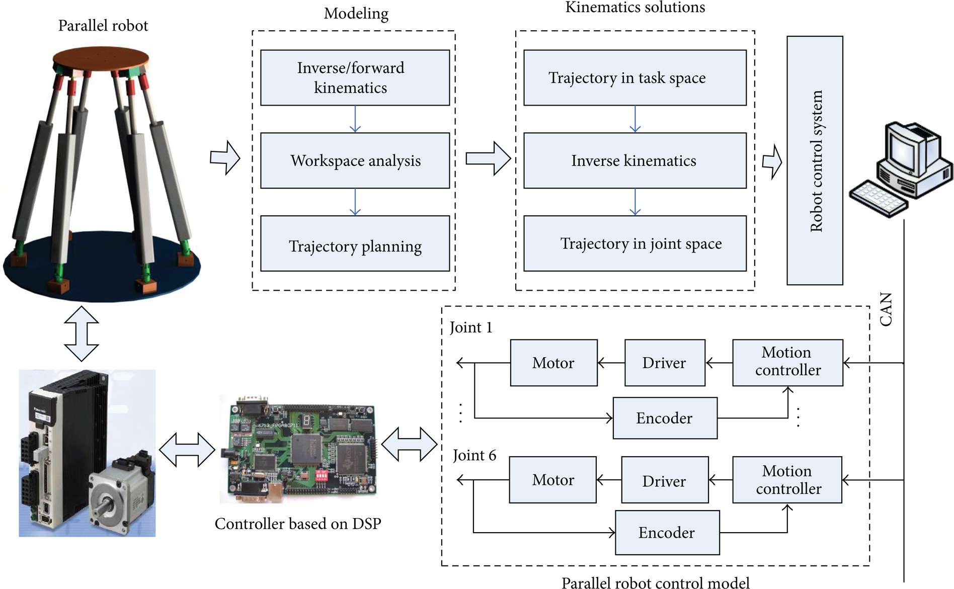
Prototype of the control system for parallel robot.
3. Control of The 6-DOF Parallel Robot
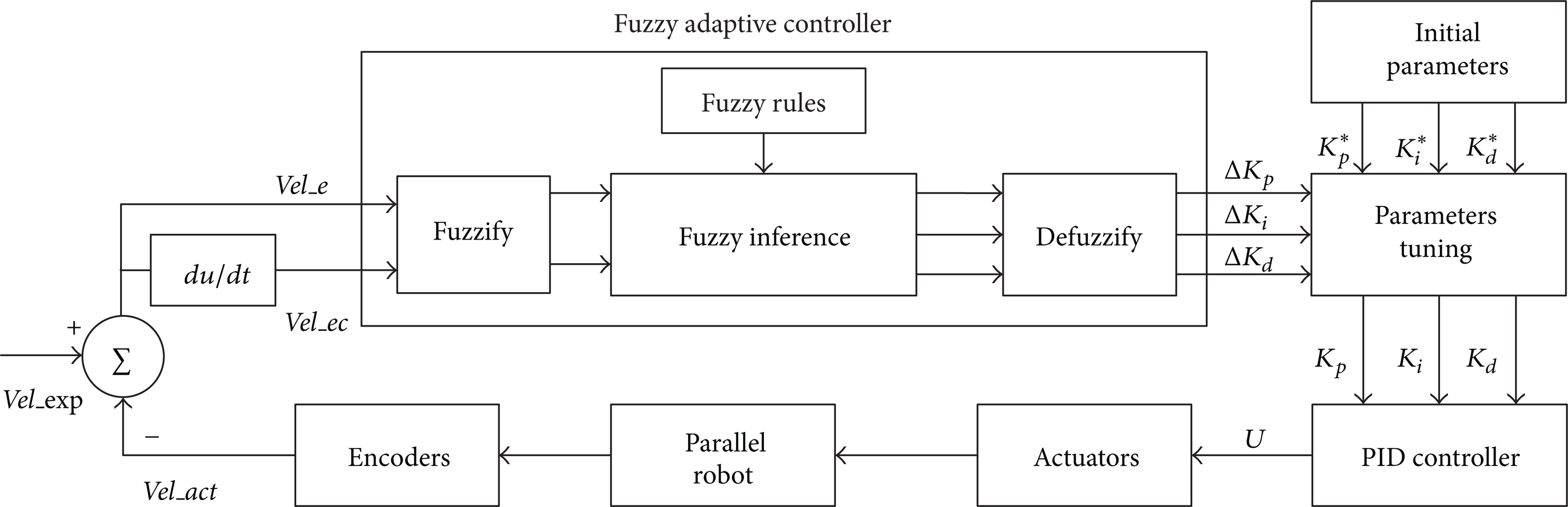
Traditional PID controllers have the fixed parameters and cannot adjust the parameters according to the control results, which makes it difficult to provide perfect performances in controlling complex system such as the parallel robots. Since fuzzy adaptive algorithm does not need the robot's dynamic model and also is able to adjust its parameters according to the external changes, the combination of fuzzy and PID adaptive controllers would further improve the performance to achieve a higher control precession [17]. The objective of this fuzzy adaptive controller is to establish the relationship between the velocity tracking errors and PID parameters through fuzzy inference. The PID parameters can be adaptively tuned according to the fuzzy rules so as to make the controller work on a changeable mode. In this way, the robotic system is able to run with a certain optimal performance even when some disturbances or errors exist in the external environment.
3.1. Control Objective
The purpose of designed fuzzy adaptive controller is to find out the relationship between the PID controller parameters (K p , K i , and K d ) and the position and velocity feedback of each joint, so that the PID parameters can be adjusted in realtime based on the velocity error Vel_e and its change rate Vel_ec. In this way, the PID parameters are able to be tuned adaptively to meet the requirements of control accuracy in a different position and orientation. In the practical environment, a high-precision incremental photoelectric encoder is used in the robotic platform for recording displacement information of each joint, while the velocity can be obtained through a differential and low-pass filter. Define the speed tracking error Vel_e and its change rate Vel_ec as follows, respectively:


where Vel_exp is the desired velocity, Vel_act is the actual velocity obtained from the encoders, while Vel_e is the velocity tracking error, and Vel_ec is the change rate of velocity error. In order to achieve smooth control for the parallel robot, the designed velocity close-loop controller consists of a fuzzy inference unit as well as a PID adaptive controller. The proposed controller utilizes the velocity tracking errors as the input variables, while the defuzzified results are utilized to adjust the PID parameters adaptively by adding them to the initial PID parameters. Figure 3 shows the proposed fuzzy PID controller.
The fuzzy PID adaptive controller for parallel robot.
3.2. Fuzzy PID Adaptive Controller Design
3.2.1. Membership Functions
The inputs of fuzzy controller are the velocity tracking error Vel_e and its change rate Vel_ec, while the outputs of the system are the additive variations of three PID parameters: ΔK p , ΔK i , and ΔK d , which are used to adjust the PID controller by adding them to the initial parameters K p *, K i *, and K d *. Define fuzzy subset of the input variables Vel_e and Vel_ec as {negative big, negative middle, negative small, zero, positive small, positive middle, positive big}, which can be denoted by {NB, NM, NS, ZO, PS, PM, PB}. Vel_e is quantized to (−3, 3), with Vel_ec to (−0.3, 0.3). Similarly, define fuzzy subset of ΔK p , ΔK i , and ΔK d as {negative big, negative middle, negative small, zero, positive small, positive middle, positive big}, also denoted by {NB, NM, NS, ZO, PS, PM, PB}. ΔK p is quantized to (−0.3, 0.3), with ΔK i to (−0.06, 0.06) and ΔK d to (−0.03, 0.03), respectively. Consequently, the membership functions of the input and output variables are shown in Figure 4 and Figure 5.

Membership functions of input variables Vel_e and Vel_ec.
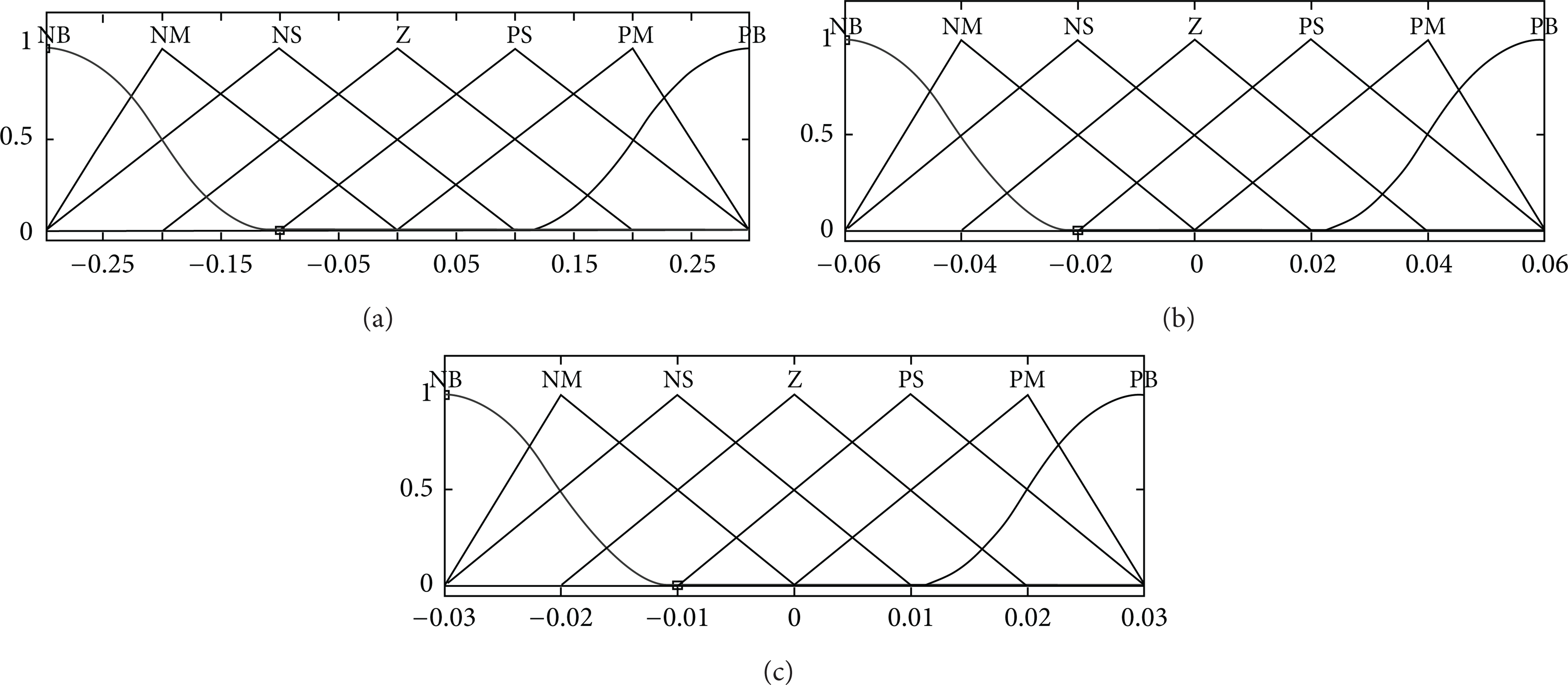
Membership functions of variables ΔK p , ΔK i , and ΔK d .
3.2.2. Fuzzy Rules
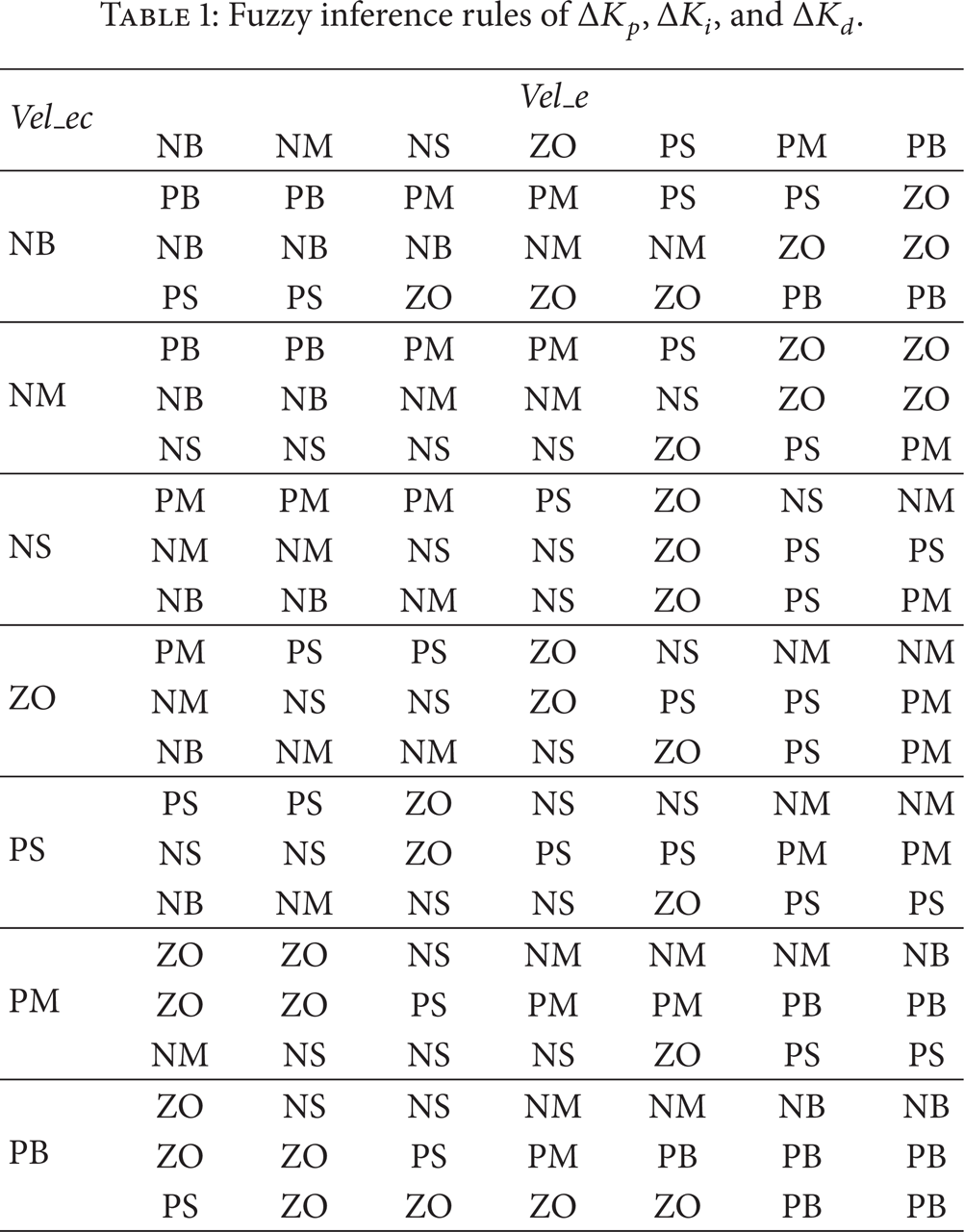
The fuzzy rules must be developed appropriately in accordance with the PID tuning principle, and the empirical relationship between the three PID parameters and the robot tracking errors must be considered when designing fuzzy rules. For example, the K p should increase when the system needs to respond more quickly and decrease when the chattering needs to be avoided; the K i should increase when control function needs to be enhanced and decrease when the overshoot needs to be reduced; the K d should increase when the errors need to be corrected earlier and decrease when the controller noise is high. Based on PID parameters tuning principle, the additive variables ΔK p , ΔK i , and ΔK d can be adjusted adaptively, and we are able to reach the fuzzy inference rules of the three parameters when the input variables are Vel_e and Vel_ec. The fuzzy rules described above are built as the “If-Then” form, shaped like: if (Vel_e is NB) and (Vel_ec is NB), then (ΔK p is PB) (ΔK i is NB) (ΔK d is PS). The fuzzy inference rules of additive PID variables are established as shown in Table 1.
Fuzzy inference rules of ΔK p , ΔK i , and ΔK d .
3.2.3. Fuzzy Inference
In this fuzzy PID adaptive controller, Mamdani inference method is adopted as a fuzzy set R (relationship) expressing fuzzy conditional statement. Considering the impact of velocity tracking errors on the adaptive PID parameters, we set the generation function of fuzzy relationship Mamdani as the max operation, and let μ(x) represent the membership function, as

Therefore, the membership function of output B* can be expressed as

3.2.4. Defuzzification
The process of converting the fuzzy variables to the accurate values is known as defuzzification or fuzzy judgment. In order to obtain accurate results of the fuzzy output, the method must be able to calculate the membership function results effectively. In this paper, weighted average method is used for outputting the membership values, which can be represented by
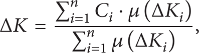
where μ(ΔK) and C i are the membership and weighting coefficients of ΔK in the collection of elements.
3.2.5. PID Parameters Tuning
According to the fuzzy rules, the fuzzy matrix of PID parameters can be obtained by fuzzy reasoning and inferring, and then the adaptively tuned PID parameters can be calculated through

where K p *, K i *, and K d * are the initial PID parameters, ΔK p , ΔK i , and ΔK d are the outputs of fuzzy inference, while K p , K i , and K d are the tuned parameters. Therefore, the fuzzy controller is able to adaptively adjust the PID parameters online based on the real-time position and velocity feedback.
4. Experimental Results
The Stewart platform in actual environment designed by our research group in WHUT is shown in Figure 6. Specifically, the detailed architecture of this platform is shown in Figure 7. The system mainly includes an industrial PC with Pentium Dual-core CPU E5400, motion controllers based on DSP boards of model TMS320 LF2407A, and Panasonic Minas servodrivers with output power of 400 W and rated speed of 3000 r/min, as well as the Stewart platform. Furthermore, the incremental photoelectric encoders are mounted coaxially with the servomotors to provide high-resolution position and velocity feedback.
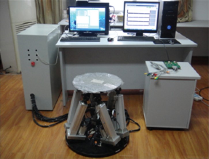
The Stewart platform designed by our research group.

The parallel robot control system composition.
Before performing the experiments, firstly the real-time position and velocity feedback of each joint cylinder should be addressed. In this experimental system, each AC servo motor is coaxially equipped with a 20-bit incremental photoelectric encoder to provide high-resolution movement information feedback. Define the detection time as T (unit: s) and the pulse count value as m within this duration and let the number of pulses generated with per motor rotation be P (that is, photoelectric encoder resolution). Therefore, within the detection time T, the number of motor rotations is m/P, so the motor rotation speed reaches m/PT (units: r/s). While the actual transmission gear ratio is n and the displacement of screw nut is L (unit: mm), the actual speed of the electric servocylinder can be obtained through

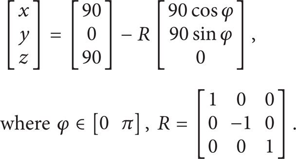
In the robotic system, the motion control of the robot is realized by solving the inverse kinematics to get the desired position and velocity of each joint. The designed robot is able to reach a wide variety of trajectories including point-to-point movement and continuous movement. For rehabilitation robot engineering applications, the trajectory of this platform can be decomposed into straight line and arc trajectories, and here an example of arc trajectory experiment is conducted. As for the configuration of this robot, the radius of the upper moving plate is 180 mm, the radius of the fixed base plate is 270 mm, and the angles of the platforms are 28° and 22°, respectively. The mass of the upper platform is 3.6 kg, and the masses of the base platform and linkages are 17.9 kg and 1.2 kg, respectively. The trajectory for upper platform is defined as follows: the initial position of the platform center is (0, 0, 0), and move the plate to (90, 0, 90); here the unit is mm. And then the platform moves by following a counter-clockwise circle, and the radius is 90 mm; thus the path planning of the moving platform is
Once we get the planned trajectory in task space, the movements of six joints can be obtained by using inverse kinematic solutions. The motion controllers developed in DSPs will receive the commands and accordingly generate the output PWM signals to drive each joint. As the 6-DOF parallel robot's position is the results of six actuators' interaction and coordination, so we can achieve the reference trajectory tracking as long as each joint of the robot can be controlled accurately. Both experimental results of the traditional PID controller and the proposed fuzzy PID adaptive controller are presented in the following parts.
4.1. Traditional PID Controller
The traditional PID controller has fixed parameters, so firstly, we have to select the proper PID parameters according to the controlled object. In this paper, the critical ratio method is utilized to adjust the parameters of PID controller. That is, firstly, to retain the proportional component and gradually increase this factor until achieving the critical state, record the parameters at this time. However, in the actual experiment, the PID parameters have to be further adjusted according to the actual control results. Under the above conditions, the robot is programmed to track a circular trajectory whose radius is 90 mm, and the duration is 50 s.
The joints' position tracking results of the traditional PID controlled parallel robot are shown in Figure 8, where we find the PID controller already able to achieve a relatively satisfied position tracking performance, especially under low-speed conditions. Meanwhile, the six joints' velocity tracking results of the PID controller are shown in Figure 9, and the velocity tracking errors of six joints can be seen in Figure 10, where the data is measured by photoelectric encoders. From velocity tracking results of each joint, we find that although the traditional PID controller can guarantee the overall tendency, the actual speed value has severe fluctuations. In this experiment, the maximum joint velocity error of the parallel robot is 1.752 mm/s, while the average velocity error of the platform is 0.154 mm/s. Particularly, the tracking errors increase gradually when the target velocity grows, especially in the period when the robot just starts to move. Because the motor itself has a quite large gravity, and there is static and kinetic friction force that has to be overcome, so the velocity control errors are obvious at the beginning. When the PID control algorithm is applied to 6-DOF parallel robot, the adjustment process is relatively slow, and the overshoot is quite significant. It is suggested that traditional PID controller cannot achieve high accuracy for velocity tracking, which is an important indicator of rehabilitation robotics. In other words, we need to introduce other intelligent control algorithms to improve the accuracy.

The robot's position tracking results of PID control.

The robot's velocity tracking results of PID control.

The robot's velocity tracking errors of PID control.
4.2. Fuzzy PID Adaptive Controller
Fuzzy PID adaptive controller is able to adjust its PID parameters according to the external changes. The relationship between velocity tracking errors and PID parameters is established in this experiment. The additive variables of PID parameters can be adaptively tuned according to the fuzzy rules, so as to make the PID controller changeable by adding the fuzzy inference output to the initial PID parameters. In this paper, a practical velocity closed-loop controller based on fuzzy PID adaptive method is developed, and the experimental data is recorded by using photoelectric encoders. As a result, the velocity tracking results of the fuzzy controlled robot are shown in Figure 11, and the velocity tracking errors of its six joints can be seen in Figure 12.

The robot's velocity tracking results of fuzzy PID control.

The robot's velocity tracking errors of fuzzy PID control.
By filtering the experimental data and analyzing the results, the maximum single joint velocity error of the 6-DOF parallel robot decreased from 1.752 mm/s to 1.120 mm/s, while the average velocity error of the platform reduced from 0.154 mm/s to 0.057 mm/s in this circular movement. From the experimental results, it is illustrated that the impact of changeable target value on the tracking accuracy has been greatly reduced and the fuzzy PID adaptive controller shows better robustness. Compare Figure 9 with Figure 11, as well as Figure 10 with Figure 12; we find that the robot's velocity tracking performance has been significantly improved, especially in the initial phase when robot starts to move, where the actual velocity trajectory can follow the desired trajectory in a better way. This is because the PID parameters can be adjusted in real time based on fuzzy rules, and it will take the current robot movement situation into account, so the proposed controller can adapt itself to the external changes.
The experimental results illustrate that the fuzzy PID adaptive method has played a significant role in the tracking accuracy improvement of parallel robots, the velocity tracking delay has been effectively reduced, and the steady state performance can also be guaranteed. In addition, the calculation amount of fuzzy PID adaptive controller is relatively small, which can be easily implemented on DSPs to meet the real-time data processing and instant transmission requirements. If the trajectory planning of the upper platform is given, the displacement and velocity of six motor actuators can be obtained, and applying the proposed fuzzy adaptive controller to drive the related joints, we are able to achieve the efficient and reliable motion control of the robot. In other words, the proposed controller can be used in various applications as long as the defined trajectory is within its constraints, and this, in turn, provides a feasible solution for position control of parallel rehabilitation robot in the future work.
5. Conclusion and Future Work
During the motion control of the rehabilitation robot, the system may become unstable due to the uncertain variations of the system loads and dynamic parameters, which would lead to the secondary injury of the patients. Therefore, it is of great significance to maintain the trajectory and velocity tracking accuracy and stability for medical purpose [18]. This paper aims at designing an effective method to control the Stewart robot used for lower limb rehabilitation. Based on the study on parallel robot's kinematic model, a prototype of 6-DOF parallel robot control system is established, and accordingly a fuzzy PID adaptive controller is proposed for velocity close-loop control. The experimental results performed in the actual experiment demonstrate that applying the proposed adaptive fuzzy control method to 6-DOF parallel robot manipulator is reasonable and valid; the position and velocity tracking accuracy can be greatly improved. Currently, it seems that there are not enough realistic applications of the parallel robot; thus it is worthwhile to propose a fuzzy adaptive controller that can achieve a good performance in the actual environment and put it into practice for medical purpose.
The future works involve improving the dynamic response of such parallel platform and obtaining a better trajectory tracking performance by combining the fuzzy controller with other advanced control techniques, such as neural network and sliding mode control strategies. Furthermore, in order to improve the rehabilitation results, force feedback between the robot and the patient should be taken into consideration; putting the position/force hybrid control and impedance control into practice is also important in this field. Finally, in order to implement the rehabilitation control strategies in the actual environment, more attentions should be attracted to biomedical signals processing, human-machine interface, and the rehabilitation assessment strategies.
Footnotes
Acknowledgments
This research is funded by the international collaboration project of Natural Science Foundation of Hubei Province, China (2009BFA006), the National Natural Science Foundation of China (51175389) and the Fundamental Research Funds for the Central Universities (Grant no. 2012-IV-088, Grant no. 2013-YB-002).