
Abstract
Composed of a single proton exchange membrane fuel cell (PEMFC), a sensor module, and a ZigBee wireless communication module, a fault diagnostic system is proposed in this work to monitor the operation of a fuel cell system. Accordingly, such quantities as cell's output voltage, current, operating temperature, and pressures of gases supplied are monitored. Subsequently, an extension matter-element model is built according to malfunctions of the fuel cell system, which are further categorized into 7 types, each with 12 sorts of characteristics. An extension evaluation method is then directly applied to diagnose such fuel cell system. A human machine interface built under LabVIEW 2009 is incorporated in such a way that a fault(s) can be detected and fixed in a timely manner such that the life cycle of such fuel cell system can be extended.
1. Introduction
As a significant progress as well as a rapid economic growth is made in human society, a tremendous amount of natural resources had been consumed already, leading to issues of immediate concern, in particular the global oil crisis and warming effect. Hence, the developments of green energy technologies are seen more critical than ever before. Among a number of alternative energy sources, hydrogen is treated as one of the most promising candidates, due to the reason that it can be burnt directly to generate heat and can be even applied to a fuel cell as an input to provide electricity through electrochemical reaction. On top of that, a high conversion efficiency up to 40~60% is seen in a fuel cell. Besides, as a consequence of technology improvement and progress made in material science, the power density of a fuel cell has been elevated largely, and fuel cells have been turned into a competitive product in market to a great extent owing to successful cost reduction activities on electrode catalysts and other key components [1].
As a device designed to convert chemical energy to electricity, a fuel cell is mainly composed of three parts, an anode, a layer electrolyte, a cathode. As such, the nature of a fuel cell is subject to the electrolyte contained and chemical mechanism. Two water molecules are formed as the outcome of a chemical reaction between two hydrogen molecules and an oxygen molecule, that is, a pollution free chemical process. Featuring a low pollution level, the development and applications of fuel cell-related technologies have received global attention [2]. However, a fuel cell performance is found as a function of the fuel purity, flow rate, and operating temperature, among other quantities.
Accordingly, aiming to develop a fault diagnostic system for a fuel cell, this work employs extension theory to precisely locate a fault(s). Through a wireless link via a ZigBee module and a GPRS module, a distant monitoring system is reached by way of Ethernet network.
2. Principles and Models of Fuel Cell
As referred previously, a fuel cell is able to convert chemical energy into electrical form, and chemical formulae are represented in (1) and (2). Illustrated in Figure 1 is an electricity generation system of PEMFC, an electrochemical and thermodynamic model [3–5], according to which a potential fault might be located as follows:


A schematic diagram of a PEMFC power generating system.
The output voltage V provided is expressed as

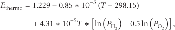

In (4),


Equation (6),
From the above equations, cell's output voltage is found to increase with the operating temperature. A cooling system would be damaged in case the fuel cell is operated beyond rated temperature [6]. A MATLAB simulation, as presented in Figure 2, demonstrates cell's performance with the operating temperature T as a parameter. In the case of

A plot of a single cell's performance under various temperatures.
3. The Fault Diagnostic System Architecture
3.1. The Full Cell System Architecture
The fault diagnostic system proposed in this work is made up of an electricity generation system, a sensor module, and a ZigBee wireless communication module. Sensed data, such as cell's voltage V, current A, the operating temperature T, and the pressure of supplied gas

A configuration of a fuel cell monitoring system.

A system entity photo.
Widely applied to industrial automation, Modbus, developed by MODICON, is an open and standard communication protocol [7]. ZigBee is a wireless communication module stipulated by IEEE 802.15.4 and ZigBee Alliance in both the hardware and software aspects, mainly applied to wireless sensor networks, industrial automation, health care, and so forth.
3.2. The Fuel Cell Failure Characteristics
Currently, fuel cells can be roughly categorized into two types: the first of which is operated based on the electrochemical reaction between pure hydrogen and oxygen, while the second is based on the reaction between the pure hydrogen and the oxygen contained in the air. The latter is further classified into two types, namely, self-cooled and pressurized. The one adopted in this work belongs to self-cooled for an advantage of being portable due to the absence of bottled oxygen. However, a major disadvantage accompanied is a short life cycle relative to pressurized. As can be found from a prior work [8], faults may be attributed to a number of factors, for example, overheating as a consequence of a cooling fan malfunction. As many as 12 characteristics are detected with a sensor module in this work. Figure 5 is a configuration of the diagnostic system, where sensor spots are marked on the surface of a gas bottle.

Sensor spots in a fuel cell monitoring system.
The characteristics acquired are applied to the diagnostic system proposed for the fault identification purpose. As tabulated in Table 1, F2 signifies an exhaust malfunction, giving rise to a drop in cell's output voltage. Indicating a malfunction in the cooling system, F3 and F4 represent an underheated fuel cell system and an overheated one, respectively. F5 and F6 denote a malfunction in the gas supply system, while F7 represents an interrupted wireless network link.
Fault types in a fuel cell diagnostic system.

Other than the inlet pressure and the bottle temperature, all the characteristics are applied to (9) for evaluating each changes, where 
It is found that (5) does not as expected provide a satisfactory identification result.
Instead, the 12 characteristics, as tabulated in Table 2, are applied to (10). As illustrated in Figure 6, 
Twelve characteristics in a system.


A signal flow graph of a fuel cell diagnostic system.
The fault diagnostic system proposed is built with an interface implemented in LabVIEW 2009. Pictured in Figure 7 is a window of such monitoring system, and each type of malfunction is indicated by individual indicator. Besides, there are two levels of diagnosis contained in such system: the first of which is built for the system level as shown in Figure 8, the second level of the diagnosis system can show the fault location of the fuel cell as shown in Figure 9. As presented in Figure 9, a blockade of the oxygen supply system is indicated in block 5.
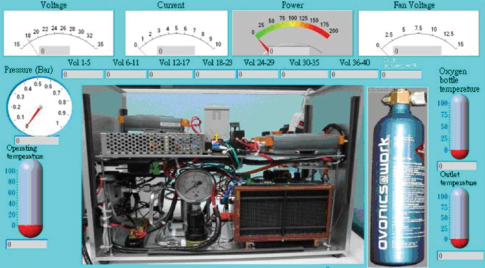
A human machine interface.

The first level of a diagnostic system.
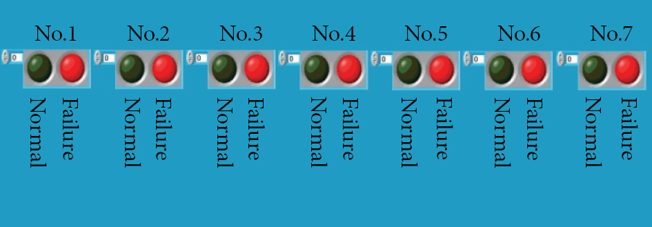
The second level of a diagnostic system.
4. The Signal Fault Diagnosis Method
Proposed in 1983 by Tsai Wen, the well-developed extension theorem has been successfully applied to a wide range of research fields, for example, artificial intelligence, decision making skill, biomedical engineering, testing technology, and so forth. It extends the binary logic into a continuous and multivalued form. Besides, a correlation function is employed as a way to represent the mature of a thing, that is, the extent that a element belongs to Characteristics of a thing is represented by a real number between
4.1. The Extension Matter Element
The term “thing” in everyday life is referred to as “name” for research purpose. A distinctive nature of a thing is characterized by a characteristic, which is quantized as a number referred to as “value.” A thing is represented by a set of characteristics, name and the value thereof. As a fundamental unit to describe a thing, a matter element, given a characteristic, a name, and a value, is represented as

Due to 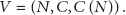
In extension theory, 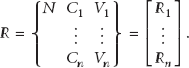
A matter-element space is portrayed in Figure 10, with the x, y, and z axes representing N, C, and V, respectively.

A matter-element space.
4.2. The Extension Evaluation Method
Underlain by an extension set and a correlation function, Extenics is developed as a mathematic tool in an effort to apply such theory to practical applications. The approach procedure is stated as follows.
Step 1.
First of all, each fault type is modeled as


Step 2.
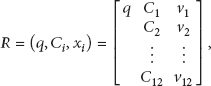
Referred to as the evaluated matter element, a set of characteristics pertains to a matter element R, represented as
Step 3.
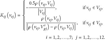
Each fault correlation function is evaluated as
Step 4.
The weighting factor 
Step 5.
Finally, all the weighted correlation functions 
Step 6.
Normalization is performed in (20) in order that the fault diagnosis value falls within the interval 

Step 7.
A fault is identified as belonging to type if in case
Step 8.
In case all the parts in a fuel cell system have been diagnosed once, then the diagnostic procedure comes to an end otherwise skip back to Step 2 for another run.
The idea of extension evaluation method is that the experiment data accumulated are classified into a certain number of level collections, to which respective ranges of real numbers are assigned. Subsequently, the pending assessment of the data is applied to each range of assigned numbers successively for the evaluation of corresponding membership grade. A higher membership grade indicates a higher level of linkage between the pending assessment of the data and such level collections and vice versa.
5. Experimental Results and Discussion
5.1. The Detector Signal
Underlain by a mathematic model built for a fuel cell and the characteristics thereof, out of which the characteristics of objects is extracted, the type of a fault(s) is identified through extension theory and grey system theory. A malfunction of a fuel cell system is reflected by a drop in the output voltage provided. Not taking proper measures in time may result in a permanent damage to the cell system. In this work, a signal data base is constructed in Excel for futuristic system diagnosis, according to which output voltage signals are plotted against time. Presented in Figures 11 and 12 are the curves indicating faults in the temperature control system (F3 and F4) and the exhaust value (F2), respectively. As many as 100 and 200 data records are made with a sampling interval of 5 seconds, a tunable quantity through the human-machine interface. The trend similarity between such two curves in Figures 11 and 12 is seen, meaning that there is no way to precisely identify the fault types in the absence of a systematic diagnostic approach. For this sake, this work is proposed as efficient means to identify faults and take required actions in a timely manner against any sort of potential damage to the cell system.
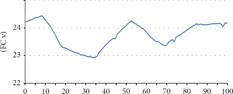
A voltage response to a malfunction in a temperature control system.

A voltage response to a malfunction in exhaust valve.
5.2. The Diagnostic Signals
As demonstrated in Figure 13, the curve in red indicates cell's output voltage versus time, while in blue indicates the corresponding diagnosis result. The y coordinates represent the identification results, namely, fault types
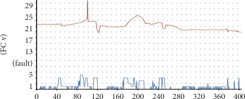
A plot of identification result against time.
Up to 80% of data records are treated as the training samples, and the rest are as the test samples. As tabulated in Table 3, the approach proposed, not requiring a training process, is found superior to k-means classifier in terms of identification rate and superior to a variety of neural network, necessitating a training process, as well.
Performance and requirement comparison among various approaches.

6. Conclusions
Presented in this work is a fault diagnostic system for a fuel cell, an easy to implement system made up of multiple Modbus modules. On top of that, a user friendly human machine interface is constructed for easy monitoring of the cell system operation. Over others, the approach proposed, not requiring a training process, acquires advantage of high recognition rate, meaning that a fault(s) in an early stage can be identified in a timely manner in order that measures can be taken to extend the life span of the cell system. Integrated with a ZigBee wireless communication module, this system can be in the future applied to a distant monitoring system, such as an alter system for a fuel cell-powered vehicle.
Footnotes
Acknowledgment
The authors feel deeply indebted to the National Science Council, Taiwan. for all the resources gained under Grant no. NSC 99-2221-E-167-031-MY2.