
Abstract
Drying is a required operation in timber manufacturing industries. Most drying processes utilise convective kilns, which involve coupling between transient heat and mass (moisture content) transfer in solids and convection in a flowing medium. In the present work, the flow field in the kiln is determined using a system approach based on a general head loss equation, whereas the coupling between transient heat and mass transfer in the timber is accomplished by a solution of a local differential model across the timber stack. The scheme is applied to study the effects of distinct geometric kiln configurations and air flow temperatures upon drying rates and moisture content.
1. Introduction
The technological advancements in the last years have made available to industries several conventional and nonconventional wood drying methods such as radiofrequency heating, press, solar, and dehumidification drying strategies [1]. Notwithstanding, convective drying is the mostly used method in agricultural, food, paper, and timber processing industries [2]. In general applications, convective drying of moist objects (e.g., lumber manufacturing, food processing, etc.) conjugates heat and mass transfer both inside the solid and in the flowing medium. The understanding of the related physics of the problem is crucial for the process control and ensuing product quality.
The industrial importance of drying processes has been translated by the increasing number of works reporting numerical prediction of temperature distribution and moisture content in convective drying problems. In convective timber drying, temperature, moisture content, air velocity, and drying rates are the most important parameters to affect product quality; that is, an incorrect setting of global parameters may cause defects such as colour heterogeneities, warp, and splits amongst others. Therefore, development of simple and effective predictive models to evaluate the process parameters is of paramount importance in lumber manufacturing industries. Riepen and Paarhuis [3] present a numerical study on the optimization of flow velocity in convection kilns. The authors conclude that there is a strong relationship between drying rate and air velocity distribution inside the kiln. Kaya et al. [4–6] devise 2D numerical models to predict heat and mass transfer during convective drying. The authors solve the flow problem to obtain the convection heat transfer coefficient in the boundary of the moist object considering a laminar flow regime. Analogy between thermal and concentration boundary layers is adopted to estimate the convection mass transfer coefficient on the surface, followed by solution of the transient diffusion problem (heat and moisture inside the object). In a similar direction, Mohan and Talukdar [2] present a 3D computational model to study the convective drying of a moist object. More recently, two works assessing convective drying of wood have been reported in the literature [7, 8]. Younsi et al. [7] utilise a 3D model to compute the turbulent flow inside convective kilns and evolution of the temperature and moisture content. Thibeault et al. [8] combine the Ansys CFX (heat and moisture transfer) and FESh++ (mechanical approximation) commercial codes to predict the thermo-hygro-mechanical behaviour of wood during convective drying.
Most literature works involving convective drying focus only on the local physics of some particular moist object (small scale). To the authors' best knowledge, there are no works in the literature based upon a system approach where the convective kiln is modelled in the real (full) scale and air flow is computed using a lumped approximation. It is expected that the kiln geometric configuration, as well as lumber stacking, and sticker number, geometry, and placement affect both the head loss and flow aerodynamics and, as a consequence, the flow operating condition (and, ultimately, the drying rate). Based upon the authors' experience in modelling and simulation of forced convection heat transfer in industrial problems (e.g., [10–12]), a full scale, globally iterative coupled simulation (in conjunction with the fan performance curve to obtain the operation point) of air flow and heat and mass transfer is computationally intensive and, within the industrial environment, would require CFD advanced users to select proper model settings. Therefore, the present system approach aims at developing a simpler model and is yet able to obtain good approximations to the physical phenomena. Following this route, it is proposed a mixed numerical model (a global approach to determine flow velocities and a local differential model to compute evolution of the timber temperature and moisture content) to predict the effects of distinct kiln configurations and air flow temperature on the evolution of drying rates, moisture content, and temperatures in a full geometric scale.
2. System Approach: The Flow Operating Condition
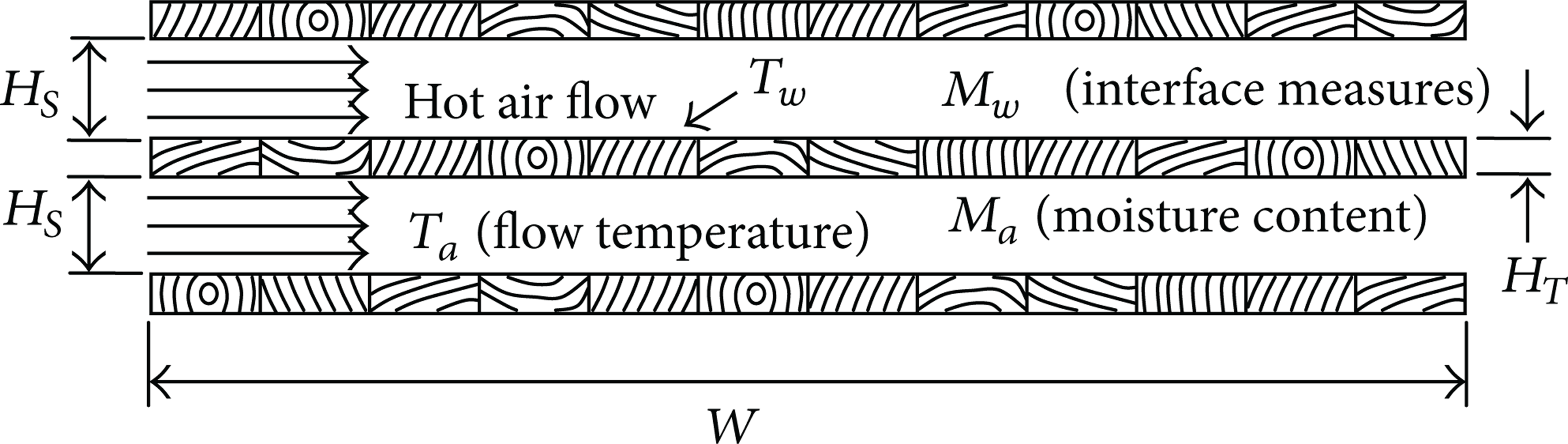
The strategy used in this work to estimate air velocity across the timber stack is based upon determination of the flow operating point of the global system—the system approach. This technique requires (i) knowledge of the fan performance curves—provided by the manufacturer and (ii) computation of the system characteristic curve. The typical system characteristic curve correlates the total head loss (or pressure drop) and flow rate in the inlet/exit plenums and timber stack, accounting for friction losses and effects of flow separation. This section describes the procedure to obtain the characteristic curve of the system and the operating condition for the compact dry kiln depicted in Figures 1 and 2.
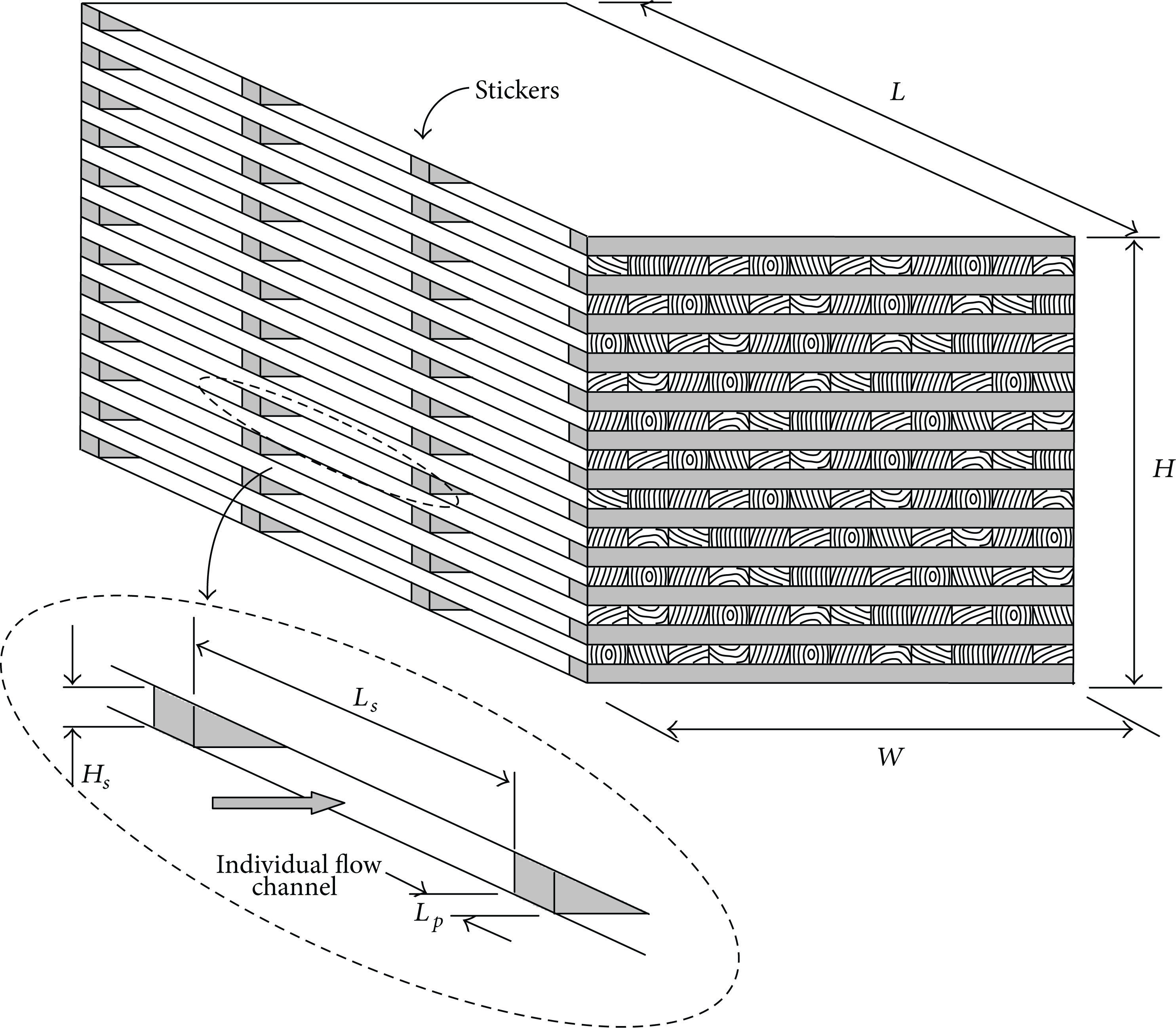
Compact dry kiln geometry: lumber stack and sticker placement.
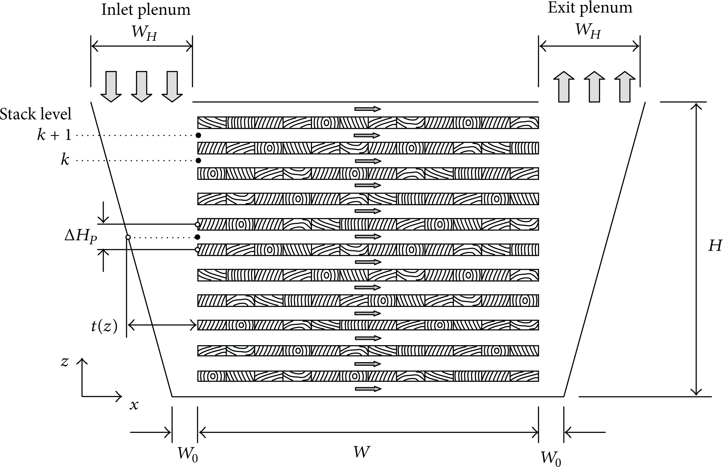
Compact dry kiln geometry: lateral view.
Air flow between two consecutive timber layers is dictated by the pressure difference between the inlet and exit plenums. Ideally, the kiln design should provide uniform pressure in both plenums, making it possible to obtain the same velocity in all flow channels. However, the plenum configuration or inadequate sticker dimensions/placement may cause pressure differences and, consequently, variations in air velocity across the stack height, which may lead to undesirable, nonuniform drying rates. The present formulation follows the concept of Nijdam and Keey [13], who developed a differential head loss equation to compute channel velocities across timber stacks assuming that the kiln configuration is such to prevent boundary layer separation at the top corner. Aiming at a discrete solution for a known number of timber layers and stickers, the proposed approach determines the flow rate based upon an equivalent flow circuit and accounts for channel inlet and exit effects and flow through parallel channels between stickers.
The geometrical information is indicated in Figures 1 and 2. The main parameters are the stack height, H, width, W, and length, L; number of stickers and corresponding dimensions, N P and L P × H S × W; number of lumber layers across the stack height, N L ; and maximum and minimum inlet and exit plenum widths, W H and W0. Such configuration causes air to flow between timber layers through parallel, N S = N P – 1 individual channels of cross-section A S = H S × L S . The stack level is indicated by k = 1, 2, …, N C (upward direction), in which N C = N L + 1. The geometry of the inlet and exit plenums, depicted in Figure 2, defines a continuous cross-section variation, A P i (z) = A P o (z) = t(z) × L, so that t(z = 0) = W0 and t(z = L) = W H .
The pressure drop, Δp c , between entrance and exit sections of a generic channel of length l c can be readily derived from the mass conservation principle and the classical head loss equation [14], so that

where subscripts “in” and “out” indicate entrance and exit sections, K is a loss coefficient (when separation takes place in contraction/expansion flows), α
t
is the kinetic energy correction factor, ρ
a
is the specific mass, A is the cross-sectional area,
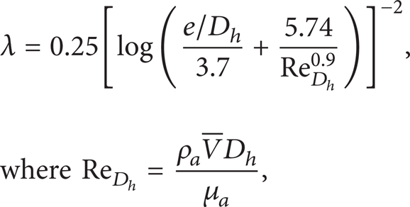
in which e is the channel roughness, μ a is the air viscosity, and D h is the hydraulic diameter.
It is relevant to notice that (1) is nonlinear, which prevents use of a direct analogy with Ohm's liner relation between voltage (pressure drop) and electrical current (flow rate). However, a similar approach can be used based upon the mass conservation and by assuming equality of pressure at the entrance/exit of the channels at a given stack level.
2.1. Equivalent Global Flow Circuit
Figures 1 and 2 show that air flows through the inlet plenum, splits into N S parallel channels at every discrete level k of the timber stack, and exits through the exit plenum. The configuration of the equivalent flow circuit is shown in Figure 3, which highlights the flow through parallel channels for stack levels k and k + 1 (Figure 3(a)) and flow through the timber stack and inlet/exit plenum stretches (Figure 3(b)). In view of the present kiln geometry and flow circuit presented in Figure 3, application of (1) requires computation of the hydraulic resistances for the inlet/exit plenum stretches, R k i and R k e (between stack levels k and k + 1), and parallel channels, R k j (between stickers for stack level k), as

in which the subscripts P and S represent plenum and individual channel measures and k is the stack level across the timber stack height; the superscripts i and e indicate inlet and exit plenum stretches and j denotes an individual flow channel at a given stack level k. The hydraulic diameter for a flow channel, D
h
S
, and the corresponding mean values for the inlet/exit plenum stretches,

where H S , L S , L, and t(z) are indicated in Figures 1 and 2.

Equivalent flow circuit: (a) channels (between two timber layers) and (b) inlet/exit plenum stretches and channels (across the stack height).
2.2. Individual Channel Approximation
Figure 1 shows that insertion of stickers between two timber layers creates parallel channels with equal inlet and exit pressures, p
k
i
and p
k
e
, respectively, at every stack level k. Furthermore, the hydraulic resistance for each individual channel at a given level k is constant, R
k
j
= R
k
S
, (i.e., equal flow rate,
one obtains

2.3. Inlet and Exit Plenum Approximation
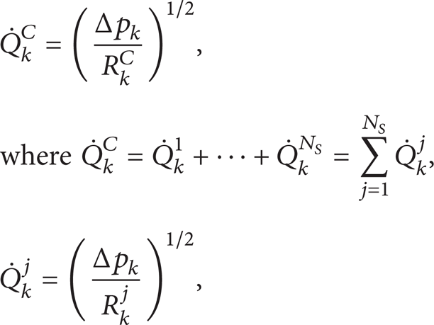
The inlet and exit plenums are split into stretches of equal height ΔH P , as indicated in Figure 2, for which hydraulic resistances R k i and R k e are computed using (3). Therefore, in addition to R k i and R k e , the global circuit configuration includes also the hydraulic resistance for stack level k, R k C , as illustrated in Figure 3(b). The pressure drop in the channels and plenum stretches for two consecutive stack levels, k and k + 1, are, respectively,

in which

The total flow rate,
2.4. Fan Performance Curve and Operating Point
Conceptually, the operating point consists in the balancing flow condition between the mechanical energy provided by fans and the losses imposed by the flow topology in the dry kiln, represented by the point at which the fan performance curve at a given rotational speed intersects the system characteristic curve. Mathematically, the flow operating condition
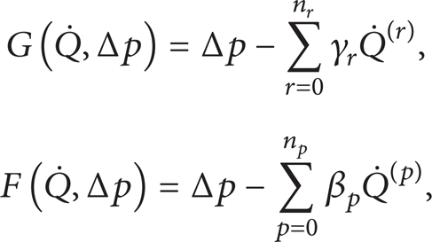
in which (n
r
,γ
r
) and (n
p
,
The fan characteristic curves are provided by the manufacturer and should indicate the respective rotational speeds; otherwise the so-called fan laws [16] can be used to estimate the performance curves within a limited range of speeds. It is worthy to mention that the fan performance curve may present a nonmonotonic behaviour with respect to the flow rate, which might require a piecewise approximation to improve accuracy. Furthermore, additional care should also be exercised to avoid operation near the fan instability region, that is, where the system characteristic curve intersects the fan curve in more than one point or both curves present similar slopes.
At the operating point, the flow rate,
3. Heat and Mass Transfer
The transient heat and mass diffusion processes in a timber layer are modelled by a one-dimensional formulation. The global and local approaches are illustrated in Figures 1, 2 and 4. Figures 1 and 2, show the timber stack and lateral view of the kiln in a full scale, whereas the local configuration is presented in Figure 4, which portraits a detailed view of the local geometry with its main dimensions and variables.
Local geometry: flow channels, where H S , W, and L S are the channel height, length, and depth (the latter is not represented in the picture: see Figure 1), respectively, and timber layers with thickness H T .
Assuming that W ≫ H T (timber layers are thin), the mathematical model comprising the energy and chemical element (moisture) conservation principles reduces, respectively, to

where z is the direction normal to the gas flow, T is the timber temperature, α T = μ T c T /κ T is the thermal diffusivity of the wood, M represents the moisture content in the solid (kg of moisture/kg of dry wood), and D M is the diffusion coefficient of moisture in the timber. The diffusion coefficient, D M , is temperature dependent, being given by the Arrhenius law

in which D∊ and DΓ are experimental constants. The present work assumes DΓ = 4.66 × 10⁻⁵ m2/s and D∊ = 3.771 × 10³ K, corresponding to the drying wood process in a wide range of temperatures [17].
Computation of the global drying curve requires solution of (10)-(11) for each individual timber layer owing to possible differences in the flow velocities across the timber stack. In addition, the boundary conditions at the solid/gas interface and the initial condition for transient heat and mass transfer problems must also be specified. The energy balance at both interfaces of a timber layer of thickness H T leads to
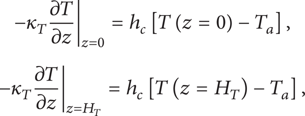
where κ T is the thermal conductivity of the solid (timber layer), T a is the air flow temperature, T(z = 0) and T(z = H T ) are temperatures at the solid/gas interfaces, and h c is the convective heat transfer coefficient. The latter is determined by assuming fully developed flow of the gas in the channels so that [18]

for laminar and turbulent flow regimes, respectively. In (13), D
h
is the hydraulic diameter, k
a
is the thermal conductivity of the gas, and
Application of the mass balance for the chemical element (moisture) at the air/timber interfaces leads to

where M a is the moisture content of the drying air, M(z = 0) and M(z = H T ) are the moisture content in the timber/air interfaces, and h M is the convective mass transfer coefficient. The coefficient h M is determined by using the analogy between thermal and concentration boundary layers, δ t /δ c ≈ Le1/3 [18], that is,
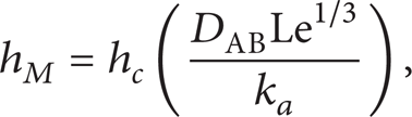
where Le = α a /DAB is the Lewis number and DAB is the diffusion coefficient of the chemical component A (moisture) in B (air). It is important to state that the procedure adopted in the present work for modelling conjugated heat and mass diffusion has also been adopted by other authors [2, 4–6] within similar framework.
The heat and mass conservation equations (10) are fully coupled through the mass diffusion coefficient, D M , and mass and heat convective coefficients, h M and h c , thereby requiring a numerical solution. The finite volume method was used in this work owing to its local conservative character and discretisation/implementation simplicity. The space derivatives are discretized by central second-order formulae whereas the time derivative is approached by the second-order accurate Cranck-Nicholson scheme. The resulting systems of algebraic equations are solved by the well-known TDMA algorithm. The procedure is classical in the literature and for more details the reader is referred to [19]. The numerical approximations for the local problems were validated against analytical solutions for a one-dimensional plate subjected to convective transfer on both sides [9]. The largest local errors for the nondimensional parameters were smaller than 1.8% (very early in the process), substantially decreasing as the process advances. Further discussions and validation of the local approximation are presented in [12].
4. Numerical Examples
4.1. Validation of the Flow Rate Model
The present system approach combines a global solution to obtain flow rates and velocities inside the channels and a local approximation to heat and mass transfer for timber layers. The critical aspect of the present model is the accurate determination of the channel velocities across the timber stack. Validation is, therefore, performed for the flow solution against a CFD simulation of a reduced size dry kiln using the Ansys CFX commercial package.
The simulations are performed for two plenum sizes, W H = W0 = 0.090 and 0.180 m, and 12 timber layers. The entrance velocity at the inlet plenum is assumed V N C P = 4.2 m/s for both cases. Table 1 indicates the geometrical data and flow information. It is important to note that, in this example, only the hydrodynamic solution is determined, especially the channel velocities across the stack height.
Dimensions and operational parameters for a reduced size dry kiln.
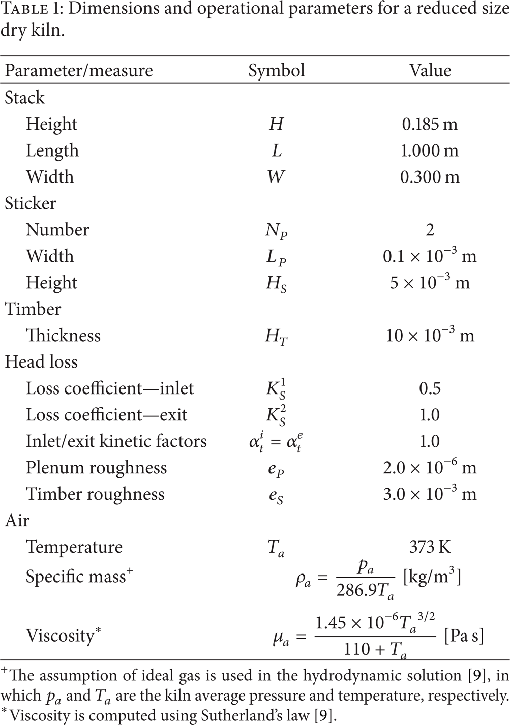
The assumption of ideal gas is used in the hydrodynamic solution [9], in which p a and T a are the kiln average pressure and temperature, respectively.
Viscosity is computed using Sutherland's law [9].
The velocity distribution for plenum sizes (a) W
H
= W0 = 0.090 m and (b) W
H
= W0 = 0.180 m is presented in Figure 5. The same entrance velocity at the inlet plenum (located at z = H in Figure 2) used in both cases gives rise to substantially different flow rates across the timber stack. In case (a), the total flow rate is

Channel velocities across the stack height for plenum velocity V N C P = 4.2 m/s and plenum sizes (a) W H = W0 = 0.090 m and (b) W H = W0 = 0.180 m.
4.2. Full Scale Simulation of a Dry Kiln
It has been well established in the literature that the air temperature and velocity dictate the drying rate. Therefore, the ideal compact dry kiln would have to combine not only uniform drying rates, but also high lumber volume and compact dimensions (e.g., by designing narrow inlet and exit plenums). Within this framework, this example focuses on two issues: (a) the aerodynamic behaviour of the dry kiln and (b) evolution of the lumber moisture content and drying rates.
The timber stack comprises 30 lumber layers (L × W = 2.40 × 1.60 m) of thickness H
T
= 25.4 × 10⁻³ m, as depicted in Figures 1 and 2. The other dry kiln dimensions and process parameters are presented in Table 2. The simulations were performed for plenum sizes W
H
= W0 = 0.10, 0.15, 0.20, 0.30, 0.50, and 0.80 m. The fan performance curve is described using a fourth-order polynomial in
Dry kiln dimensions and operational parameters.

Fan performance curve for a rotational speed ω = 1740 rpm: fourth order polynomial regression, n
p
= 4, in

4.2.1. Hydrodynamic Solution: Velocity Distribution across the Timber Stack
This section highlights the effect of the plenum size on the hydrodynamic performance of the compact dry kiln using the formulation discussed in the previous sections. The system approach provides the operating point corresponding to the intersection between the fan performance curve and the system characteristic curve. Figure 6 presents the operating conditions for different plenum sizes, in which

System approach: fan and system characteristic curves and operating points for plenum sizes W H = W0 = 0.10, 0.15, 0.20, 0.30, 0.50, and 0.80 m.
The operating point represents a global measure of the hydrodynamic balance in the dry kiln. For each such point depicted in Figure 6, the global flow rate,
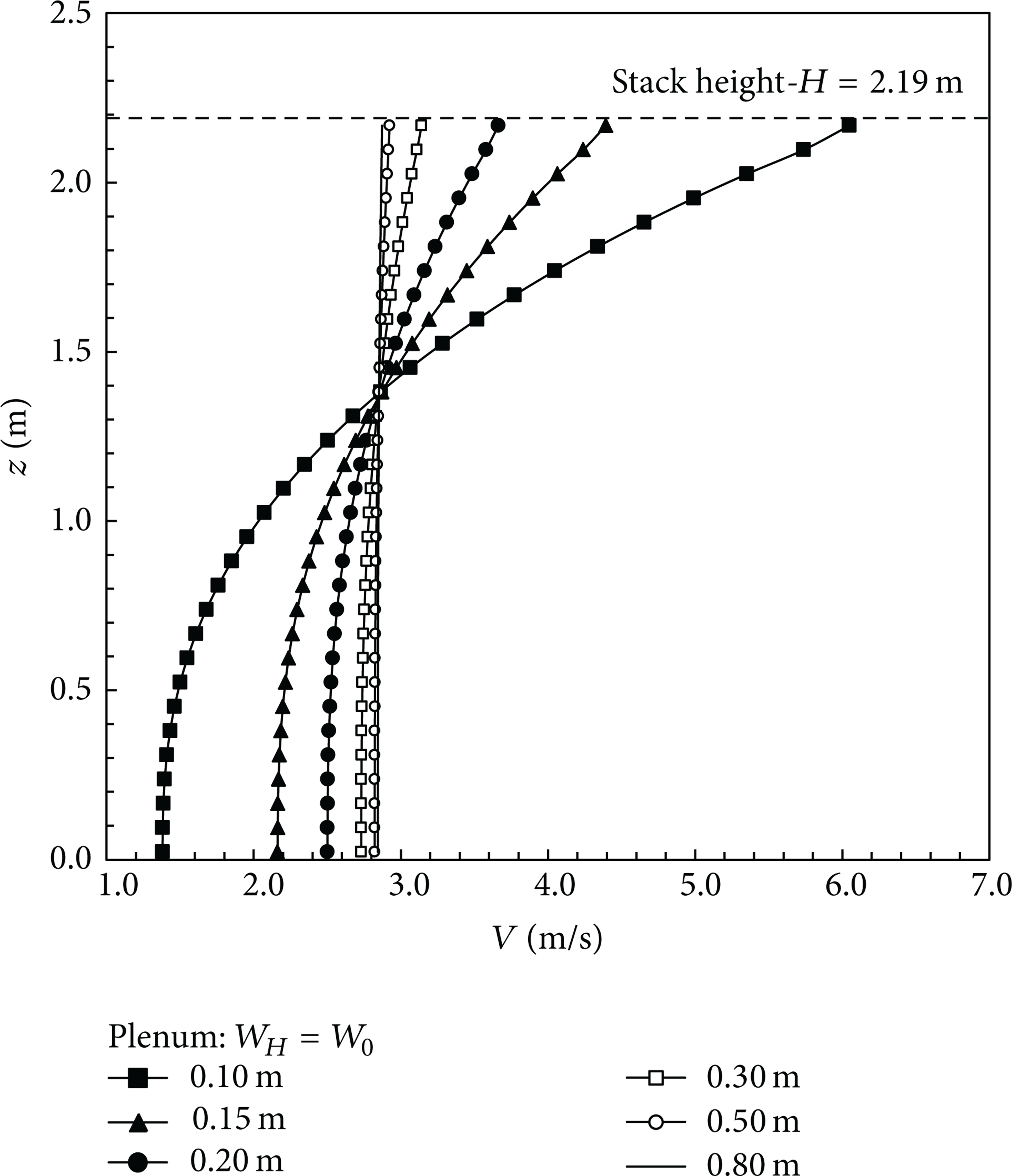
Velocity distribution across the timber stack for plenum sizes W H = W0 = 0.10, 0.15, 0.20, 0.30, 0.50, and 0.80 m.
4.2.2. Lumber Moisture Content and Drying Rates
The physical model dictated by the governing equations and corresponding boundary conditions establishes that, in general, higher velocities yield higher convective and mass transfer coefficients at the lumber-air interface. In addition, the strong temperature dependency of the moisture diffusivity leads to an equally strong correlation between the air flow temperature and moisture content evolution along the drying process. Therefore, a physical understanding of the dry kiln behaviour regarding both effects is essential to defining drying strategies within practical industrial applications. This section is focused on such physical aspects, in which the effects of the air flow temperature and plenum size are investigated. The timber and other kiln/process parameters are defined in Table 2. The time step used in the simulations to solve the heat and mass conservation equations is Δt = 0.1 s.
The previous section features the effect of the plenum size upon the velocity distribution across the timber stack. The ensuing effect upon the drying process for a narrow plenum is shown in Figures 8 and 9 which presents the average moisture content,
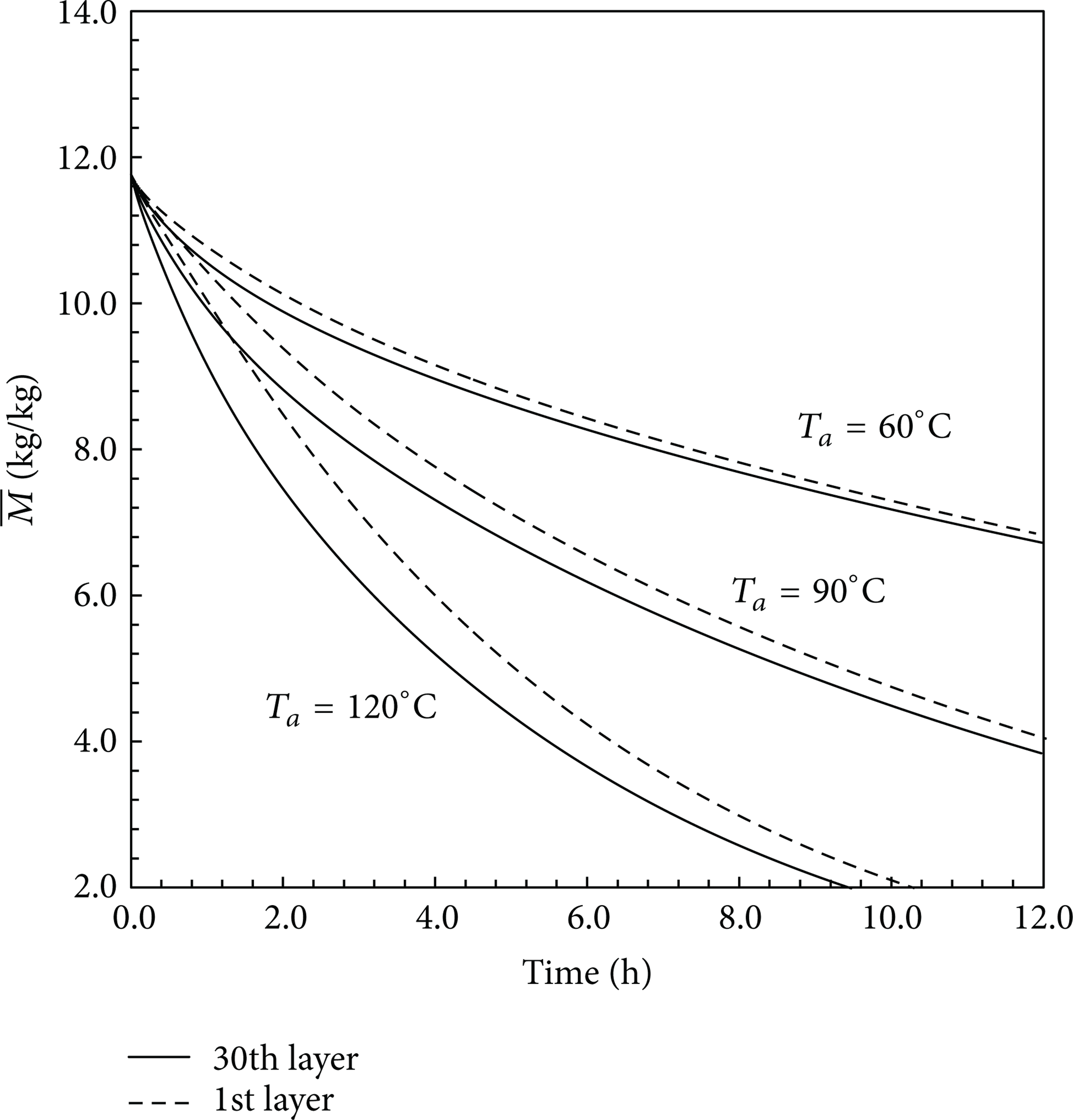
Average moisture content for a plenum W H = 0.1 m.
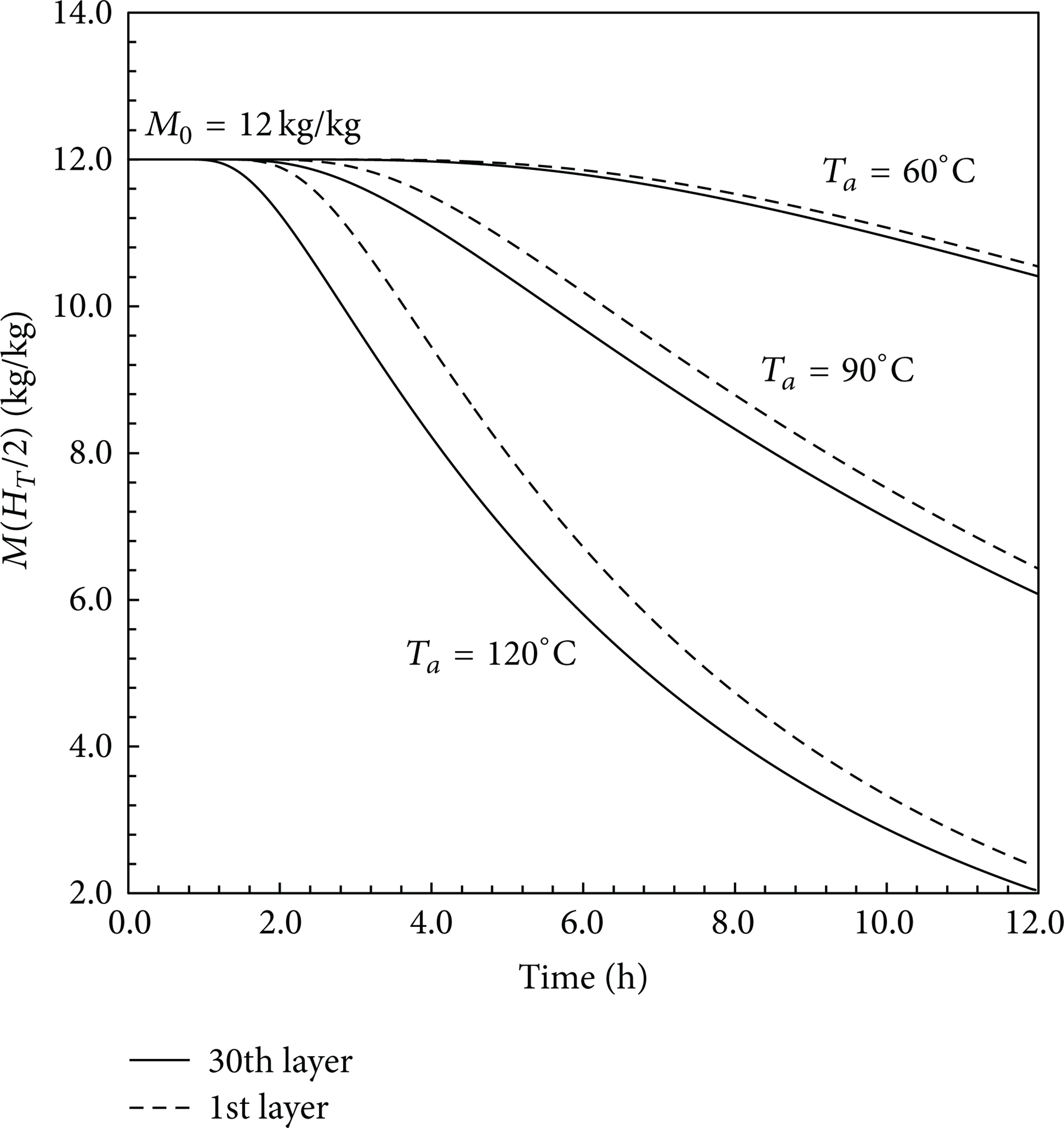
Moisture content at z = H T /2 for a plenum W H = 0.1 m.
The heat and mass transfer coupled effects are featured in Figure 10 which shows the differences in heating and drying rates for the 1st and 30th timber layers for a narrow plenum. The aforementioned higher influence of the air flow temperature is expressed in higher heating and drying rates, that is, variations of the average temperature and moisture content within a single timber layer. Furthermore, the differences in air velocities across the timber stack (see Figure 7) cause substantial changes in heating and drying rates, especially early in the process.

Heating rate,
It is worthy to notice that, as the plenum size increases, differences in air velocity decrease, leading to homogeneous heating and drying rates across the timber stack. Figure 11 presents

Heating rate,
The dynamics of the drying process is summarised in Figure 12 which shows
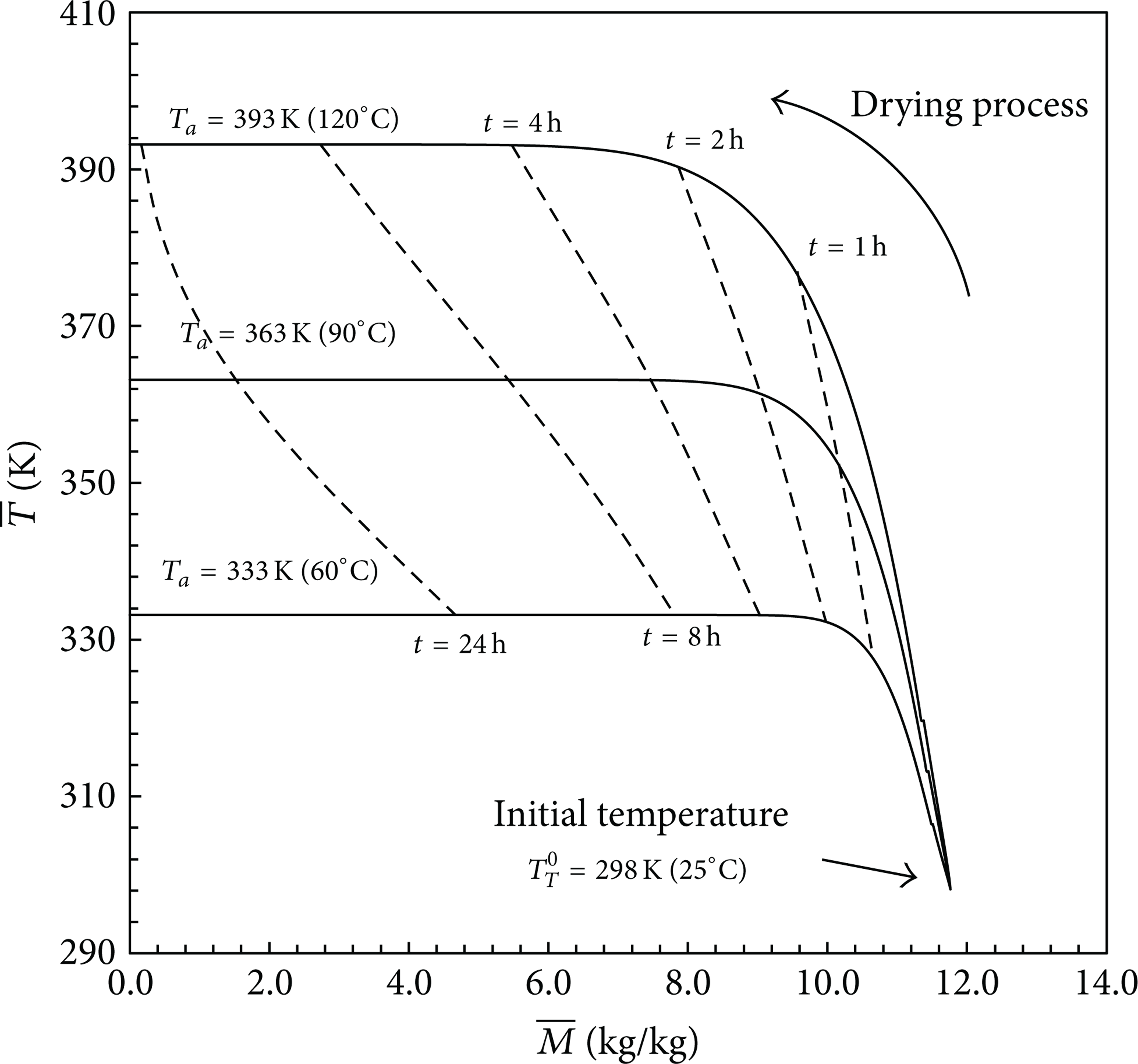
Evolution of the average timber temperature,
5. Conclusions
Convective drying is one of the most widely used drying strategies in industry. The process is performed in dry kilns, in which heated air flows through a lumber stack comprising timber layers separated by stickers. The physics of the problem encompasses the hydrodynamic description of the air flow, conjugated heat, and moisture transfer within timber layers and convective heat and moisture transfer at lumber-air interface. In this work, the actual air flow distribution is determined using a system approach, which provides the kiln operating flow condition (the point at which the fan performance curve at a given rotational speed intersects the system characteristic curve). The air flow velocities across the timber stack at the operating point are used to compute the convective heat and moisture coefficients at the timber surface, which in turn are used to solve the fully coupled heat and moisture transfer problems.
This class of problems requires definition of geometric and operational dry kiln parameters able to provide both high drying rates and uniform moisture contents across the timber stack. The former is justified by economic reasons, whereas the latter is required with the objective of ensuring good quality of the final product (avoid warping, decolouration, etc.). The most critical aspect of this problem is the correct computation of the channel velocities across the stack height. Therefore, in order to ensure that the present approach is acceptable, channel velocity solutions for a reduced size dry kiln are compared with the Ansys CFX commercial code. With the objective of evaluating the uniformity of the drying process across the stack height, the effects of the kiln geometric configuration (plenum sizes) and air flow temperatures are investigated. The fully coupled simulations of a compact dry kiln have shown that higher air flow temperatures increase drying rates (a positive aspect); however, the effects of a nonuniform velocity distribution are magnified, that is, inhomogeneous drying rates across the timber stack (a negative aspect). Therefore, an industrial solution must seek a compromise between both effects, which may eventually lead to changing the sticker number and dimensions (to improve velocity uniformity), establish progressive air heating (to reduce the effect of inhomogeneous velocity distributions) and even replace the air circulating system (providing a different fan characteristic curve).
Footnotes
Nomenclature
Conflict of Interests
The authors affirm that they have no financial support or conflict of interests with manufacturers of any commercial software mentioned in the paper.