
Abstract
The integration of environmental aspects in design frameworks has become a necessity for manufacturers to maintain their market position. This is especially true in the Computer Aided Design (CAD) phase, which is the last phase in the design process. At this stage, more than 80% of choices have been made. However, the environmental impacts generated by the remaining choices are significant. Features Technology (FT), the core of the CAD phase, is used to integrate environmental aspects. This paper presents a literature review of different works based on FT to ecodesign products. First, we present an overview of features in CAD systems. Second, we present a critical review of works done on ecodesigning with features that we divide into two subsections: the first one concerns CAD-Life Cycle Assessment (LCA) integration (methodologies, prototype tools, and commercial tools), and the second one, works using FT in CAD phase to reduce the environmental impact of one life cycle stage such as material selection or manufacturing. Finally, we propose an approach based on FT for ecodesigning products to promote simple new ecodesign tools which will help the inexperienced designer.
1. Introduction
In the earlier stages of design process, the reduction of Environmental Impacts (EIs) was the purpose of much research. This was due to the increasing demand for eco-friendly products. The amount of data provided by Computer Aided Design (CAD) systems enables a complete Life Cycle Assessment (LCA). Features technology (FT) provides the necessary data to realize a life cycle inventory (LCI), which is the second stage of an LCA according to ISO 14040. We propose a model to integrate CAD and LCA systems based on features. The objective is to extract data and provide an environmental evaluation which would be comprehensible to a designer; the model should deal with different possible scenarios and show the optimal solution. A number of steps are necessary to attempt this: necessary data for LCI must be extracted (raw material, manufacturing process possible, transportation, use, and end-of-life scenarios); possible scenarios need to be evaluated; the designer must be shown the influence of his/her choices in real time; the optimal scenario must be selected. That is why the integration between CAD/LCA tools has greatly evolved. There are tools for real-time evaluation such as solidworks sustainability [1], in which the designer can visualize the impact of his/her choices till features attribution. But several gaps and problems persist. In this research, firstly, we present an overview of features in CAD systems. Secondly, we review related studies done on ecodesigning with features in CAD phase. Finally, we propose an approach based on FT in order to present an environmental assistance to the CAD designer.
2. Overview of Features
The evolution of CAD systems has allowed nongeometric information to be integrated in a purely geometrical model (e.g., engineering constraints, tolerances, or material) through high technological entities (features) that have been introduced in most current CAD systems. Shah and Mantyla [2] present needs and advantages of features over geometric models. They configure features as objects that represent the designer's intent; this intention is maintained during the different phases of product development. According to Bidarra and Bronsvoort, modeling features compared to conventional geometric modeling enables the combination of functional and engineering information on the form in a product model [3]. For Ghodous, this FT facilitates the integration between different phases of product development such as design and manufacturing [4]. With the features approach, the geometrical objects are formed by an assembly of simple elements, such as a chamfer in a mechanical part. The final geometric form of the part results from the application of a sequence of features configured and integrated into the 3D model.
2.1. Features Definitions
Different definitions have been proposed for features. For Wilson and Pratt, features present a field of interest in a product model [5]. In Smith and Dagli's work, features are defined as high-level design primitives with their attributes, their qualifiers, and restrictions which affect the functionality and/or the ability for the product to be manufactured; that is, they can describe the shape (size and dimensions), precision (tolerances and finish), or material (type, properties, and processing) and vary with the product and the manufacturing process [6]. In the design field, according to Shah and Mathew, features are the elements used in generation, analysis, and evaluation of a product model [7]. In manufacturing, Salomons defines a feature as product data, related to functional specifications, manufacturing processes, or physical design properties [8]. In design and manufacturing, Pratt and Bedford consider shape features as elements conforming to rules that enable their recognition and classification [9].
2.2. Types of Features
Different types of features have been elaborated: Shape Features Constraint Features, Precision Features (or tolerance), Assembly Features, Functional Features (sets of features related to specific functions which may include information on design intent, nongeometric parameters related to function or performance, etc.), Material Features, and Primitive Features.
2.3. Features Representation
Most research on the geometric representation of features shape is oriented to volume representation (3D), in combination with surface representation. For example, we can cite the representation based on Boundary Representation (B-REP), and on Constructive Solid Geometry (CSG), as well as hybrid representation as shown in Wang and Ozsoy [10].
2.4. Techniques of Features Creation
Several techniques have been developed for the creation of models based on features. These techniques are divided into two main approaches according to Allada and Anand [11] and Shah and Mantyla [2].
Features recognition: features are recognized from a geometric model applying rules of recognition. More features models, describing the same product, can therefore be derived.
Design features: a product model is developed based on predefined features. In this case, a product's explicit geometry is created from the features model.
In order to obtain a feature-based model, feature recognition and feature-based design are the two main approaches used. To evaluate a part environmentally, nongeometric data has to be attached to the designed object. However, the recognition approach causes the loss of all nongeometric data, which can be provided with feature-based design approach. Hence, the interest is oriented to the latter approach for ecodesigning products in the detail design phase.
3. Ecodesigning with CAD Features: State of the Art
In order to help companies design “green” and sustainable products, it is necessary to implement integration between CAD tools and sustainable methods, both of which are related to the product Life Cycle. Such digital integration allows the Ecodesign process to be supported in the early stages of product development. Retrieving part of the information available from the CAD system (e.g., volume, geometry, material, and the energy needed to form the part) is necessary to realize an environmental evaluation. FT—also called “green feature” by Xin et al. [12], has been successful due to its high level of representation and modeling capabilities. In this section, we present how FT can be used to develop new Ecodesign tools (CAD/LCA integrated tools) covering the Environmental Evaluation (EE) of all life cycle stages. We then show how it can be used on CAD phase to reduce EIs of a stage such as material selection or a green manufacturing process. Figure 1 presents the two essential categories of research on the topic “Ecodesign with CAD features”: CAD-LCA integration and Ecodesigning one life cycle stage. Each category is divided into three subcategories.

Essential axis in the topic “Ecodesign with CAD features”.
3.1. CAD/LCA Integrated Tools and Methodologies Based on Feature Technology
Bonvoisin and Thiede describe a part, in CAD systems, as a 3D model, composed of a set of features which describe the part's geometry. It is used for the realization of a process plan which is defined by a set of operations. An operation is a treatment unit of one or many features by a machine. A feature can be realized by one or many operations [13]. Mäntylä et al. show that features are generally expected to form a basis for linking CAD with downstream manufacturing applications and for organizing databases for design data [14]. As described in ISO 14040, an LCA requires several iterations between goal scope definitions, inventoryanalysis, and impact analysis [15]. Hence, Life Cycle Inventory (LCI) is strongly linked to CAD features, essentially in retrieving necessary data. Figure 2 presents a simplified model for the Life Cycle Inventory Analysis (LCIA) phase. FT, then, is the core of most CAD/LCA integrations whether methodologies, tool prototypes, or realized tools. We have chosen to focus primarily on studies that help us establish our approach.
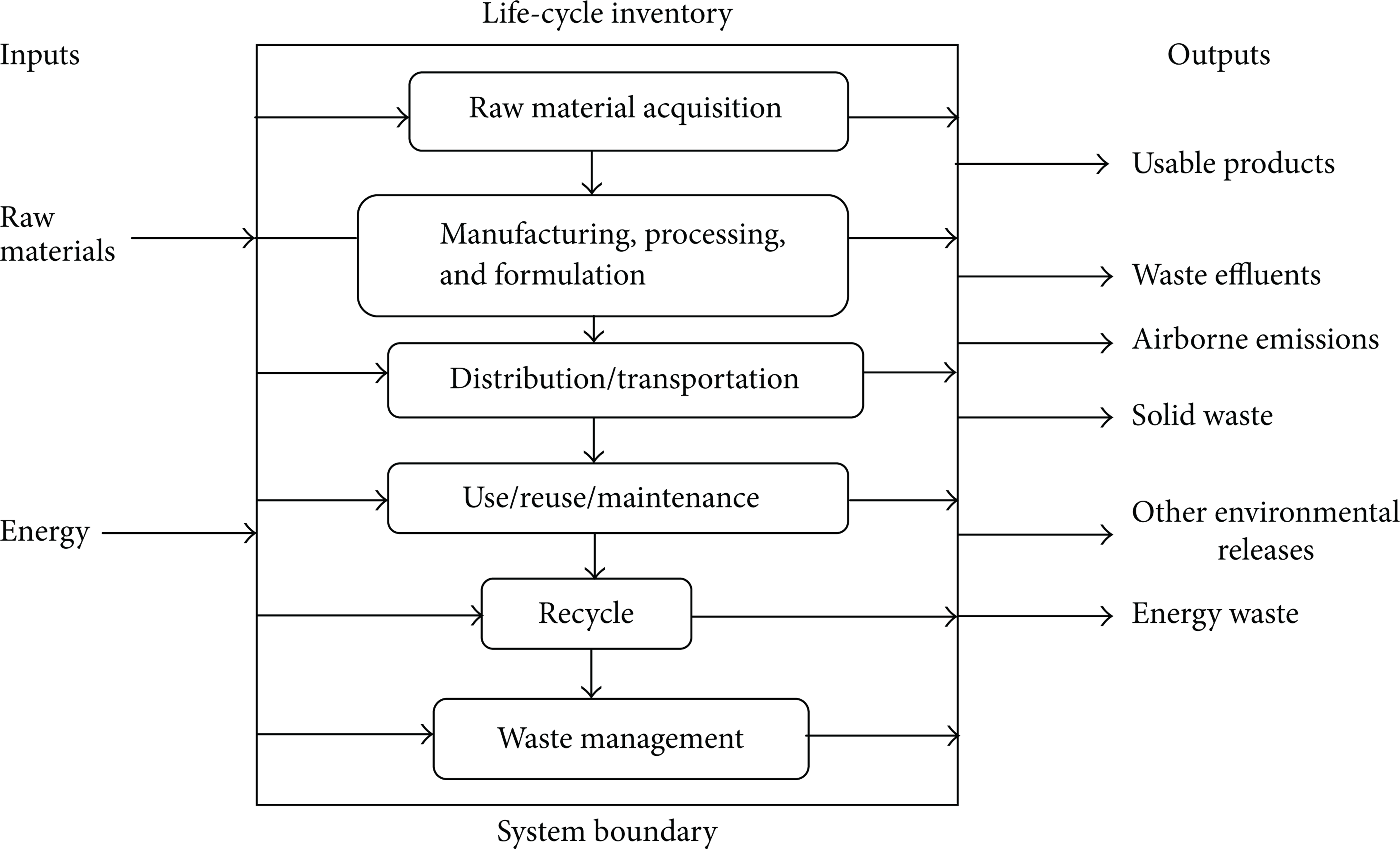
LCIA proposed framework by SETAC [18].
3.1.1. Methodologies Based on Features for CAD/LCA Integration
Data exchange is an important step in the integration. For this reason, data extraction, data transfer, and data exchange are initially the most important tasks resolved by research such as Otto et al. [16, 17]. Otto presents a framework, where a data transfer between the two systems is performed. The LCA required data is extracted from a geometric model based on features.
Within the approach taken, efficient access to the LCI-relevant data is realized by using a search index in order to extract the necessary features for practicing an LCA. FT supports data migration in order to identify input-output entities in the conceptual design phase [19] and in the detailed design phase [20].
The data provided by features can be divided into explicit information, which is related to part geometry, and implicit information, which is related to part process [16, 21, 22]. Success is obtained when data extraction and migration between two different types of software are carried out; thus for a digital tool, data exchange is necessary. Marosky [22] explores these works and presents a structure of an algorithm that allows mutual data transfer between CAD (SolidEdge) and LCA tool (SimaPro). This transfer is based on extracting data from a product CAD model which consists of assemblies, subassemblies, parts, and features. The objective is to evaluate the environmental impact of a component as well as the whole product. In a previous paper [23], we proposed a simple ecodesign tool by integrating CAD and LCA. Geometric characteristics of a CAD model were analyzed to estimate their environmental influences during all the phases of a product life cycle. The tool consists of a special geometric data base containing the impacts of all existing design technical solutions of a product; critical geometric features and forms concerning environmental impact are identified, after which designers can select the optimal solution in terms of feasibility and ecology. However, when it is a case of a new product, the designer may encounter problems using this tool (Chui and Chu [24]). The data extracted from CAD systems represents an LCA model; this model helps us to approximate the environmental impact of a virtual product. Although a model for a complete LCA has yet to be developed, we can cite Yangl who presents a new Rapid Life Cycle Assessment (RLCA) model based on features [25], in which corresponding design parameters of a product concept are indentified based on the mapping relationship between “green features” and conceptual design information. “Green features” is a group of green design information covering the entire lifecycle of products [12]. Green features are characterized by green attributes, and different green features have different attributes. For example, a material feature has such attributes as material type and material quantity; a manufacturing feature has such attributes as manufacturing energy consumption and manufacturing emissions.
The lack of common format between CAD and LCA systems has been resolved thanks to FT. However, all methods consider a CAD geometric representation as a collection of data to assess the environmental impact of one life cycle scenario. We note that presenting alternative scenarios and their impacts is still to be developed. However in reality, a part can be realized in different ways. Also, it is necessary to provide a digital real tool to be used in industries. For example, we found prototype tools for CAD-LCA integration where features, extracted from CAD systems, are the core of an LCA model. In the following section we present these prototypes.
3.1.2. Prototype Tools Based on Features for CAD/LCA Integration
Realizing a CAD/LCA integrated tool is an aim of researchers to help nonexpert designers to ecodesign products in terms of the environment. In the literature, we have identified prototypes of tools based on the extraction of CAD data from features in order to evaluate environmental impacts of products, such as the “DEMONSTRATOR” developed by Mathieux et al. [28]. This prototype tool binds CATIA (a CAD software) and EIME (an LCA software). CATIA is connected to a Product Life Management (PLM) system that extracts all data provided by different used features. The established system then selects necessary LCA data and transfers them to EIME to calculate and show the environmental impact. Following Jain [27], we deduce that the use of the integration between PLM and CAD systems is useful to develop our approach. Jain presents a plugin (Eco-fit) designed for 3DS-max using the Eco-indicator99 (EI99), an ecoassessment methodology and database designed to evaluate CAD-based products. A screenshot of this tool appears in Figure 3. There is also “EcoCAD” presented by Cappelli et al. [29], which is based on the analysis of the tree structure of a CAD project composed of assemblies, subassemblies, parts, and features. The lack of these prototypes is their dependence on tools used in the authentication of their proposed methodologies. Like the module implemented in SolidEge, Abad-Kelly et al. [30] also connected Solidworks (CAD) and SimaPro (LCA) using macros. Computer aided sustainable tool “CAST Tool” presented by Morbidoni et al. [26] tried to overcome this gap by providing a prototype with an open access database, allowing products to be evaluated regardless of the CAD or LCA systems used (cf. screenshot Figure 3). This work is compared essentially to the sustainability module of the commercial tool “Solidworks Sustainability” [1]. Benefits are essentially due to selecting more than one production process, introducing lifecycle scenarios and extracting the right amount of geometrical and nongeometrical data from the CAD data structure and PLM databases. “CAST Tool” overcomes many weaknesses such as the single scenario introduced where the evaluation of different possible scenarios is available. However, the evaluation is postmodeling that is realized on a final part where modifications are difficult to implement, especially when it is a complex part. This explains the need for a real-time evaluation tool. A real CAD-LCA integrated tool is also needed. In the following section, some of the existing commercial tools are presented.

3.1.3. Tools Based on Features for CAD/LCA Integration
Commercial CAD-LCA integrated tools are essentially based on data exchange between the two different systems (CAD and LCA). Output data from the CAD system represents the input data for the LCA system. This data is essentially information provided from different types of features attributed by the designer. “EcologiCAD” is one CAD-LCA integrated tool which aims at the environmental evaluation of virtual product prototypes. It is developed by Leibrecht [32]. It is based on a client-server concept, where the information model represents the server. The information model also provides functionality to further applications via an application programmable interface (API). “SolidWorks Sustainability 2010” [1], developed by Dassault Systems, allows environmental assessment in real time once a feature has been attributed. It evaluates the environmental impacts associated with the material and manufacturing selections chosen by the designer and is most applicable for detailed design, as complete dimensions and tolerances are required for the simulation. Hence, to estimate the potential ecological footprint for another product with the same design requirements, it is necessary to provide a new full-scale CAD model.
Sustainable minds provide a smooth Graphical User Interface (GUI). Its advantage relative to the other software is having the ability to see tradeoffs between different designs of a product. It can be used at all stages of Conceptual Design, based on the extracted information from attributed features. The outputs are in equivalent CO2 emission or the commonly used North American single-figure process values for impact assessment [31]. This may be incomprehensible for nonenvironmental expert designers. It is thus necessary to provide a translation of such outputs into the designer field knowledge. In Figure 4, we present screenshots of “Solidworks Sustainability” and “Sustainable Minds.”

3.2. Feature Technology for a Single Green Life Cycle Stage
Several studies have been undertaken to assist the designer in the CAD stage in predicting and reducing the environmental impact of a product life cycle stage (material or machining process selection; adopting an environmentally conscious process plan; or promoting disassembly to facilitate recycling or reuse).
3.2.1. Material Selection
The first stage of a product life cycle is material selection. Attention focuses on reducing extracted resources; using recyclable materials and many other precautions can be taken in this step. Abdalla and Ebeid divide material selection into two phases, material quantity and material type. Material quantity is dedicated to conserving environmental resources where designers try to minimize the amount of materials used in manufacturing the product [33]. The amount of material of a part is determined by summing different attributed geometric features. Taking into account environmental aspects till the design phase implies optimizing the volume of the designed shape, as well as selecting the most ecological and adequate material. Hence, the objects of this design phase are resources use reduction, for example, by choosing recyclable materials. For this, software tools such as “Eco-Audit” have been developed. This tool is mostly relevant for detailed design. The advantages of this software are that it is possible to explore alternative options relatively easily in the design stages, and it can apply to 19 material processes. Granta Design [34] and Autodesk Inventor CAD software are integrated. In the same way, Granta Design developed “Eco Materials Advisor” where it is possible to propose similar alternative materials. CES selector is also a software package developed by Granta Design and Cambridge University [35]. It is a material and process selection software using a systemic procedure based on design constrains (constraint features). A screenshot of this tool is presented in Figure 5.

Screenshot of granta design tool “CES selector.”
3.2.2. Environmentally Conscious Transport
The geometry of a product has an influence on its transport phase [36], because to calculate transport impacts it is necessary to introduce two essential parameters: a product weight and volume box. Weight and volume boxes are being reduced, especially when many products are being transported. For example, for an old geometric model a transported quantity is “X” and for an ecodesigned geometric model (box volume and weight reduced) the product quantity transported is “a*X” where (a > 1). Relating the environmental impact of this phase to part geometry is clearly an area for future research.
3.2.3. Environmentally Conscious Manufacturing Process
A feature is a local shape of a product directly related to the manufacturing process. It is used to reduce the environmental impact of the different parameters in the production phase. The majority of studies found in the literature takes into account the following three axes: evaluation of process EIs; selection of green process planning from different alternatives; and selection of green process parameters such as cutting fluid or machining tool. The integration of CAD and Computer Aided Process Planning (CAPP) is successful in generating different possible process plans in real time and their EIs. Moreover, it is possible to select the most appropriate machining tool with low EIs and also the optimum scenario. These benefits are possible thanks to features models that provide the necessary data for an LCI. We present below the most important works that guided us.
(1) Evaluation of EIs of a Process Plan and Selecting the Greenest One. The evaluation of manufacturing environmental impacts is present in much research. It is oriented to reducing or avoiding processes which have an impact on ecosystems, human health, and so forth. Sheng et al. [37], Munoz and Sheng [38], and Sheng and Srinivasan [39] analyze, in their respective work, the environmental impact of dissimilar waste streams. They apply a scoring system which evaluates factors such as toxicity, carcenogenesis, irritation, flammability, and reactivity, reducing complexity of processing alternatives through a feature-based approach. A hierarchical part planning strategy for environmentally conscious machining is developed [39], and it is shown that a feature can be machined with different scenarios. The purpose is to choose the least impact set of machining sequences. Figure 6 shows the example considered by Sheng to demonstrate the influence of changing the order of machining sequences on environmental impacts of a production process. However, machining a part can be realized feature by feature or by set of features. In [37] Sheng et al. decompose the environmental impact component into “micro” analyses of individual features [40] and “macro” analyses of feature interactions [41]. To evaluate the resources and environment attributes of a/manufacturing process, Zhang et al. [42] present an Input-Process-Output (IPO) model and an evaluation index system based on a scatter degree combination evaluation method to solve the inconsistency produced by different evaluation methods in order to select the greenest process plan. This task presents the core of several works.

Influence of machining sequences order on the EIs of a part consisting of three types of features: a pocket, a hole, and a finished planar face [39].
More than the evaluation of EIs, features are useful for selecting green process planning, such as the multiobjective optimization decision-making framework model of process planning for green manufacturing established by Cao et al. [43] to put forward a new process planning strategy for green manufacturing and to develop a process planning software tool. In 2006, Tan et al. [44] developed a new production process which determines a method focusing on sustainable manufacturing. It is based on case-based reasoning, expert systems, and FT for designing a new component's process flow. A sustainable development assessment is the basis of this process flow.
Cao and Tan methods developed for green CAPP selection have to be developed in order to be used as a numerical methods integrated in CAD systems. Zhao et al. [45] also propose a method for environmentally conscious process planning. The method begins with an existing process plan and then identifies impactful process steps and associated design features, in terms of manufacturing cost and environmental impact. Alternative processes that can achieve these features are then considered to generate alternative process plans. This might be useful to integrate into CAD-LCA integrated systems to help a designer compare different alternatives till features attribution. Nawata and Aoyama [46] propose a new life-cycle design system specifically applicable to machined parts. The system automatically generates life-cycle assessment (LCA) feedback for the design process through the effective linkage of life-cycle inventory data with computer-aided design/computer-aided manufacturing (CAD/CAM) data by feature-based modeling. Hence, the important deduction that can be retained from CAD/CAM/CAPP integration is allowing the generation of different possible alternative machining scenarios.
Each scenario has environmental impacts related to the parameters of the process plan attributed. FT, in CAD phase, can help the designer select, from possible alternatives, the greenest process.
(2) Selection of Green Process Parameters. Manufacturing process planning is based on a set of parameters such as cutting tool, cutting fluid, or machining tool. Tan et al. [47] used FT in selecting the most ecological cutting fluid and machining tool because they are important parameters in developing green products. In a similar vein, the selection of an ecological machine tool is the aim of Jiang and Zhang's study [48], where they develop the model called Vector Projection Method. This method, based on FT, creates a reference index system to justify machine tool selection, by considering resource consumption and environmental impact due to part features which needs an energy input/expenditure (electric mechanic, pneumatic, etc.) to be realized. Estimating the required energy and optimizing it presents a challenge for green manufacture. Possible production energy consumption scenarios in a feature level are studied by Deshpande et al. [49] and assessed through MTConnect standard methodology. Other process parameters, such as finish cut and feed rate, generate EIs due to their relation to the part quality. Helu et al. [50], using FT, develop a methodology showing that the impact of green machining strategies such as part quality on achieved surface quality is most influenced by the finish cut (s) and feed rate. Improving part quality can also reduce life cycle EIs.
CAD and CAPP integrations are able to provide more Life Cycle scenarios for the part in a real time. It is therefore necessary to integrate these benefits into CAD-LCA integrated tools to realize environmental evaluation in real time and also choose the greenest process plan from existing possible scenarios. These contributions can be accompanied by a green end of life with promotion of design phase disassembly and recyclability.
3.2.4. Design for Green End of Life
For many products, the End of Life (EoL) phase is the worst phase in terms of sustainability. In the last decade, much research has focused on minimizing the environmental impact of this phase till the design process. FT is used in the CAD phase to select an optimal product structure from the design alternatives corresponding to lower assembly/disassembly costs, while complying with specified recycling and recovering rates. It also chooses a small set of parts to be disassembled to meet with the green directives and suggests an economical disassembly process (Chu et al. [51]). Zhang and Kuo [52] develop a graph-based heuristic approach to generate a disassembly tree in order to undertake the disassembly analysis and study the product structure and disassembly, ensuring the recording of the physical properties of components such as weight and volume. Güngör [53] proposes a method which is applicable to the detail design phase. The importance of connectors between different geometric features attributed in Design for Disassembly (DfD) is indicated. These features are evaluated with an Analytic Network Process (ANP) method.
Optimizing the disassembly sequence of mechanical systems is very useful in order to improve maintenance and recycling activities (i.e., to reduce costs, times, and number of operations). A new virtual disassembly environment, based on two different algorithms, is presented by Cappelli et al. [54] by using features such as those shown in Figure 7. Takao and Niall [55] with their support system design consider the recycling from its start point. It reduces the amount of waste at the EoL over time reduction disassembly. Abu Bakar and Rahimifard present a Computer-Aided Recycling Process Planning for EoL Electrical and Electronic Equipment [56].

Possible scenarios of disassembly sequences [56].
4. Proposed Approach for Ecodesigning with CAD Features
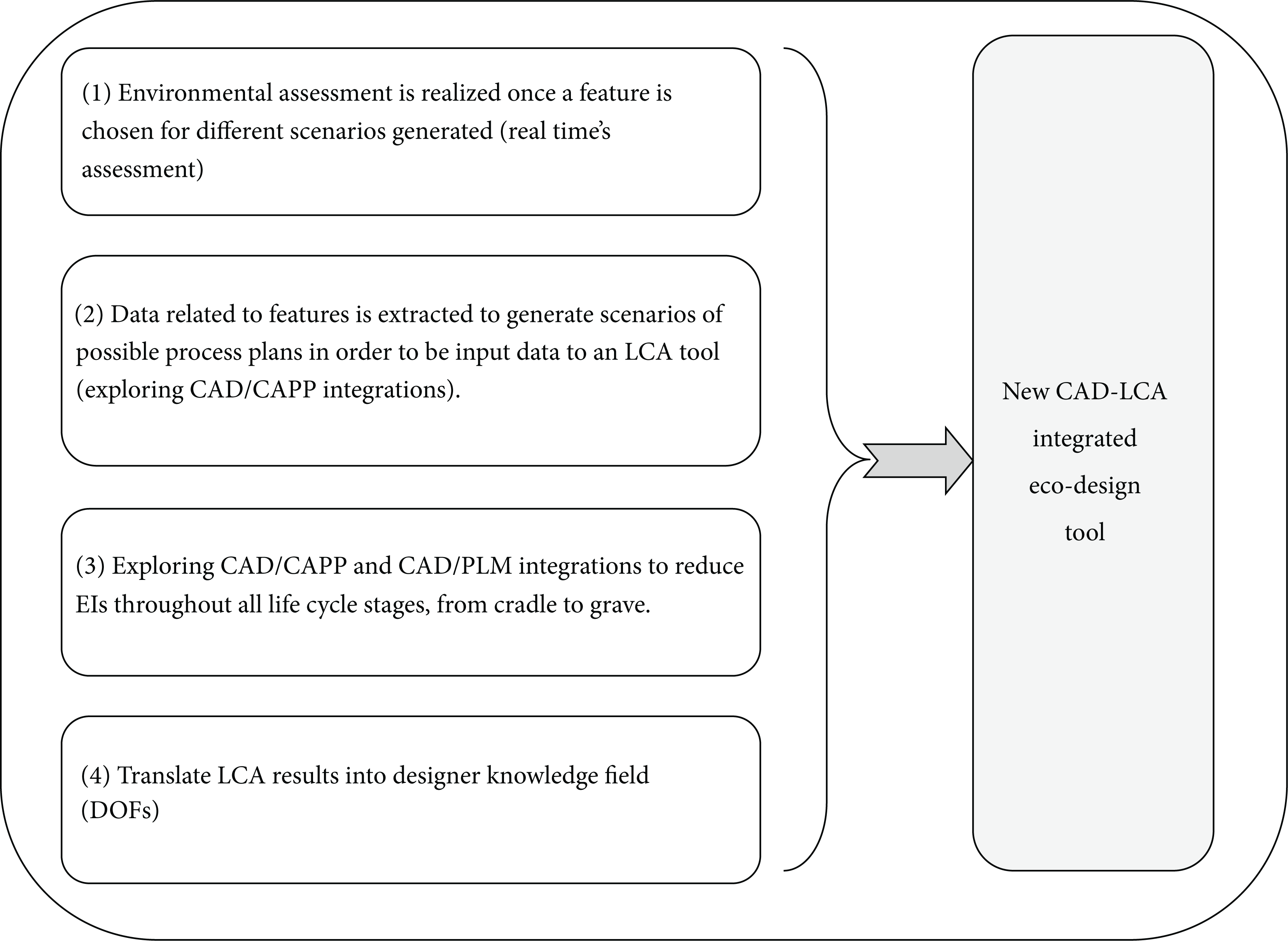
Resulting from this literature review, Figure 8 shows a summary of ecodesign works on CAD phase based on FT. Ecodesign could focus on one life cycle stage or take into account all life cycle stages. A framework of the four most important benefits found in the state of the art above based on FT is shown in Figure 8. This framework has served in our previous work to develop a new methodology based on FT to integrate CAD-LCA systems [57]. This methodology considers benefits extracted above from the literature review presented. However the methodology presented requires development. Figure 9 represents a model of a new Ecodesign tool applying the approach proposed above. It is composed of a connector which collects necessary data for an LCA tool from CAD, CAM, CAPP, and PLM systems. Once the environmental evaluation is completed, graphical representation is shown to the designer. The graphic allows, at the user interface, the optimal scenario to be selected from those proposed. The necessity of reducing products' EIs has led researchers to develop new ecodesign tools in order to help designers choose the ecological solutions in CAD phase where Degrees of Freedom (DoFs) in the acting zone are limited [58].
Benefits framework of FT in ecodesign.

Framework of a new ecodesign tool with CAD/CAPP/PLM integration.
The data transfer of the majority of CAD-LCA integrated tools and methodologies, found in the literature, is based on FT. This technology has been used in generating scenarios in CAPP and for the choice of optimal scenarios/solutions in terms of cost. Based on functionalities offered by FT and CAD/PLM integrations, we propose a new Ecodesign framework. Exploring this approach, a new Ecodesign tool, “Green-CAD,” with two interesting features will be developed. First, this tool can extract features data in order to generate scenarios of possible process plans. These scenarios represent input data to a tool (exploring CAD/CAPP integrations).
Second, an environmental assessment can be undertaken once a feature is chosen for different generated scenarios (real time EE which is based on exploring CAD/CAPP and CAD/PLM integrations to reduce EI throughout all life cycle stages from cradle to grave).
5. Conclusion
Despite the number of studies that explore CAD features for ecodesigning products at each stage of the product design process, industries do not yet efficiently integrate environmental aspects in design processes. Through our literature review and research observations, it appears that digital tools are needed to help nonexpert environmental designers. The latter needs to include environmental aspects of their virtual prototypes in the CAD phase by promoting the environmental impacts reduction in all product life cycle stages, from cradle-to-gate till the features attribution. We have presented a framework that might help resolve some difficulties that currently prevent product designers from systematically integrating environmental considerations in their activities. This framework links benefits acquired in different life cycle stages in reducing environmental impacts. It is based on FT and requires the development of more efficient CAD-LCA integrated tools (material selection, environmentally conscious process plan, energy consumption, disassembly, etc.).
In our future research work, a comprehensive model of the interactions and information flows between CAD systems and LCA software will be established, and the model will be developed into a prototype tool that will be tested through a case study.