
Abstract
The aim of this work is to analyze the stress and the strain fields in the brake caliper mounts of front motorbike suspensions produced by the braking action. First of all, some formulae useful to evaluate the maximum braking force in function of the vehicle features (e.g., total mass, centre of gravity position, tyre dimension, and brake disk diameter) have been developed. A mathematical model useful to calculate the axial, the bending, and the torque stresses on the braking caliper mounts has been then defined. The model has been developed by comparing the theoretical results with those obtained by some numerical analyses, based on the finite element method. An ad hoc test equipment has been, finally, designed and manufactured in order to define and analyze experimentally the strength of different types of brake caliper mounts and, at the same time, to verify the proposed model.
1. Introduction
The brake caliper mounts installed in front motorbike suspensions, basically, can be divided into two categories based on the layout of the caliper fastening screws: (i) standard traditional caliper mounts mainly used on low and medium powered motorbikes and (ii) radial caliper mounts used in high powered motorbikes which have been installed at axle brackets (terminal parts of suspensions) in the early 2000s. Figure 1 shows both types described above. As shown in Figure 1(c), in radial caliper mounts the fastening screws are aligned along the disk radius; this structural solution has the advantage to be stiffer than the traditional one and allows using brake discs with a different diameter by simply adding or removing some spacers between the mounts and the caliper. Finally, in radial mounts screws are mainly stressed by axial loads instead of tangential ones.

Type of brake caliper mounts:(a) and (b) traditional mounts and (c) radial mounts.
Since it is really difficult to relate the loads to the actual stresses acting on the front motorbike components by applying analytical methods, producers usually force fork manufacturers to perform a significant number of tests on those elements important for the user safety. For example, tests on joints between axle brackets and wheel pins have been extensively analysed in [1] as well as those between steering plates (forks) and legs (stanchions) produced by the braking phase [2]. The main results of the aforementioned papers are to provide some analytic models useful to calculate the stress and the strain on those components without performing any type of experiment. Furthermore, the initial force generated by the screws is essential in order to lock the joint through friction and to avoid any dangerous failure. For this reason some specific tests have been performed in order to relate the torque moment and the initial force generated on these types of coupling [3–5]. In the previous papers, the importance of friction coefficient definition is pointed out because the friction value may strongly influence the stress field of components. This paper aims at defining a model useful to predict the stress and strain produced in the caliper mounts. Motorbike producers normally provide the test specification and procedure regarding the brake caliper mounts: the test consists in applying a positive and negative static force on the mounts appropriately constrained. Usually this kind of tests represents the final validation of the product necessary to be performed before starting the production phase. Due to the complexity of these components, their final tests are, actually, the only method to validate the design activity. Two examples of test methods are shown in Figure 2. In the first one (left picture of Figure 2), the whole fork is fixed in its fully compressed position (namely, with its maximum diving) arranged on a horizontal axis and with a stated external force directly applied to the wheel; the whole braking components (caliper, disc, and pads) are installed on the fork in order to contrast the external force. The maximum diving position of the fork is applied to limit the maximum bending moment acting on the stanchions at the fixed-end support and to simulate the compression occurring when braking forces are applied. The second method (right picture of Figure 2) implies that a stated external force is applied to a plate, which is equivalent to the caliper disc system. In fact, this plate is connected to the mounts via bolts and also has a hole where the wheel pin is placed; such wheel pin must be constrained to both ends. Both types of tests have advantages and disadvantages. The first one definitely gives a better representation of the real behaviour of the structure but it is more complex in terms of test preparation: not only the fork but also the whole fore carriage must be available (wheel, disc, brake caliper, and braking system). This is not always possible. Moreover, in order to keep the fork fully compressed, without any additional external horizontal load, the internal springs of the sliders must be removed. The second example is easier to set up, but it requires the correct calculation of the external force to be applied to the plate.

Example of two different test methods.
In conclusion, as shown in Figure 2, the braking force can be applied to the wheel or directly to the ideal contact point between the disc and the pads after properly determining the magnitude and the direction of such force.
2. Methods and Results Achieved
2.1. Braking Force
As a general rule, the estimation of forces involved is obtained by considering the hardest braking condition, namely, the capsizing limit in a rectilinear motion [2, 6–8], where the load on the front wheel has the highest value whereas the load on the rear wheel decreases till zero when the rear axle starts rising from ground. With reference to Figure 3, the value of force F R can be obtained based on the dimensions of motorbikes by simply imposing the equilibrium equation (1) as
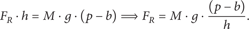
The lower this force, the easier to reach the capsizing condition which is favoured by a lower total mass and by the high and forward position of the barycentre. Deceleration d, expressed with g units (9.806 m/s2), which corresponds to imminent capsizing, is equal to the ratio between (p – b) and h and only depends on the barycentre position. However, the maximum theoretic deceleration force (F R = – M · d) must be compared with the tire/asphalt adhesion limit: according to the Coulomb friction law, the force tangential to the wheel F R equals the product between normal force x · g and friction coefficient μ (2). Typical values of the friction coefficient between the tire and the asphalt are included in the range [0.4–0.8] as

Therefore, the ratio between (p – b) and h can be considered as the minimum value of the friction coefficient required in order to reach the vehicle turnover condition.

Motorbike dimensions used for calculation.
Analysing the forces acting on the front suspension and induced by braking phase, the equilibrium must be, firstly, imposed on the wheel under the action of F R and F D . In fact, with reference to Figure 4, rotation equilibrium can be imposed around the wheel pin obtaining the value of force F D , which acts on the average disc radius R D , on the ideal contact point with the pads (3) as

All forces, which act on the fork stanchions and generate the maximum bending moment on the ideal fixed-end support caused by the presence of forks and of the motorbike chassis are schematically represented on the diagram of Figure 5. In fact, by knowing the total mass M of the vehicle and the pilot, the braking force applied to the wheel F R (1), (2), and the braking force applied to the disc F D (3), these forces can be referred to the wheel pin and they can be halved, as the pin is connected with the two legs. In the case of a fork with a single brake caliper, in addition to these forces we also have the whole F D force, which is shared between the disc and the mounts. This force is applied to the average radius R D perpendicularly to the connection with the wheel pin. As shown in Figure 5, by fixing the disc radius, the position of the brake caliper affects the value of the bending moment on the fixed-end support: this value depends on the angular coordinate φ theoretically included in the range [0 – π]. The component perpendicular to fork F D Y and the parallel one F D X depend on cos (φ) and on sin(φ), respectively.

Equilibrium around the wheel pin between forces F R and F D .

Diagram of the forces acting on the single-disc front suspension induced by braking.
2.2. Stresses on Brake Caliper Mounts
After having calculated the forces acting on the fork during the braking phase, and particularly the force F D which acts on the brake caliper mounts, the stress and strain field can be calculated and studied. In order to exactly determine the stresses involved, a simplified mount model was initially taken into consideration, namely, one without the presence of fillets and stiffening ribs, which locally alters the distribution of stresses. The original and the simplified geometries are shown in Figure 6, whereas the nomenclature required to describe the stress state is shown in Figure 7. The total braking force F D , inclined with respect to the axis stanchion, was split into two components F D X and F D Y , which are parallel to the coordinate system. Therefore, the actual stresses, with reference to Figure 7, can be separated into (i) the normal compressive stress induced by F D Y , (ii) the flexure acting in plane X-Y due to the application of F D X , at a distance y from the average plane of the mounts, (iii) the flexure acting in plane Y-Z due to the application of F D Y , at a distance z from the average plane of the mounts, and finally (iv) the torsion in plane X-Z due to the application of F D X at a distance z from the average plane of the mounts. The difficulties in defining the structural operation and calculation diagram of the stress state are mainly due to the shape of the components (De Saint Venant hypotheses are no longer valid) and to the hyperstaticity of the connection (external load must be subdivided depending on the stiffness). Due to these difficulties, the four types of stresses described above have been studied separately using the superposition effect. Moreover, in order to obtain a reliable calculation model, more than 700 numerical analyses based on the finite element method (FEM) were carried out in linear elastic field, in order to compare them with the theoretic results obtained by using the theoretic diagrams and formulae of De Saint Venant hypotheses. The force components F D X and F D Y have been applied to the holes of both mounts via the remote force command provided in Ansys R11 (software used for FEM analyses) with respect to the coordinates x, y, and z of the application point of the force shown in Figure 7. Since both mounts are actually connected with each other via the brake caliper, which may be considered as a rigid element that causes the connection hyperstaticity, it was decided to use a stiff behaviour for the connection of the remote force.

Original caliper mounts and simplified model used for the calculation.
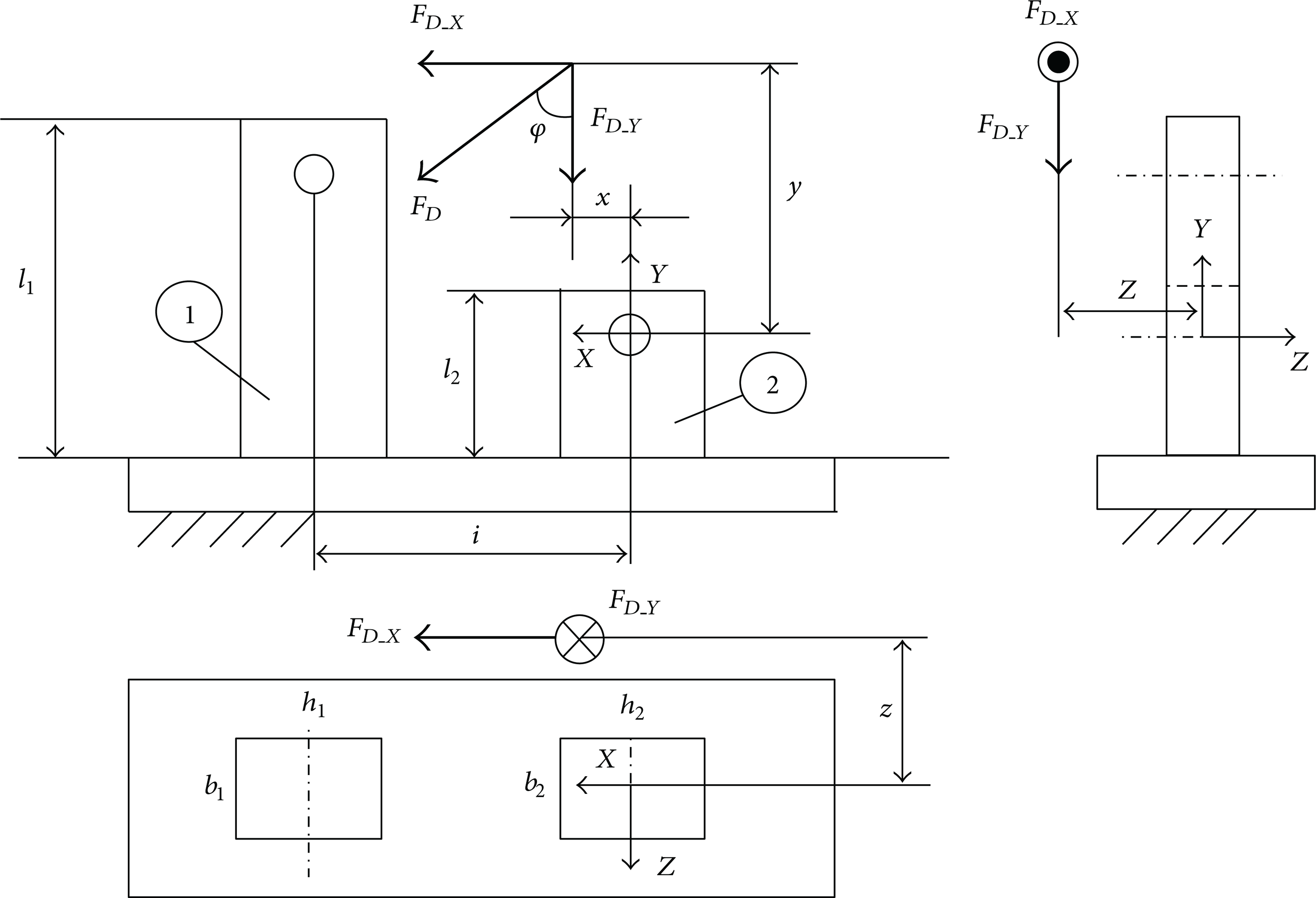
Simplified caliper mounts and nomenclature used for the calculation model.
Starting from a normal compressive stress, the fraction of F D Y acting on mount 1 and on mount 2 have been obtained using the diagram of a beam on two supports:compressive stresses are obtained from (4). The compression on both mounts, which does not depend on coordinate y, is uniformly distributed over the section of the mounts and its value is always quite low as

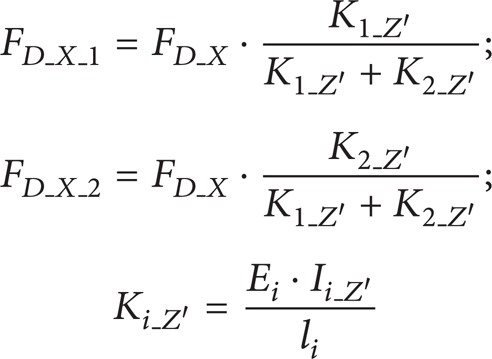
The study of flexure due to F D X acting on plane X-Y is based on the structural diagram proposed in Figure 8: total force F D X is divided on mount 1 (FD X 1) and on mount 2 (FD X 2), based on the flexure stiffness of both mounts (Ki Z′ = E i · Ii-Z′/l i being E the Young's Modulus, IZ′ the moment of inertia calculated with respect to barycentre axis Z′ and l the length) that are working in parallel as a mechanical stiffness system.

Structural diagram used for studying the deflection in the plane X-Y of the mounts.
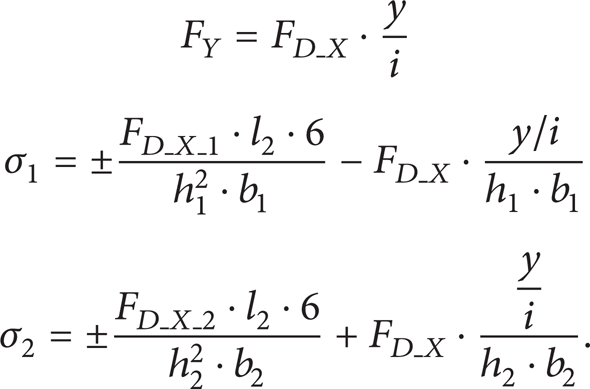
This simple calculation can be applied if both mounts are equally high: in the case of different heights, F D X must be moved to the application point of the lower mount (height l2) and then calculated depending on the stiffness and introducing the moment of transport via the action of two equal and opposite forces F Y , which induce a compression on the longer mount and a traction on the shorter one. The full calculation of the stresses on both mounts is defined by (5). The maximum stresses generated by deflection in plane X-Y are given by (6) as follows:
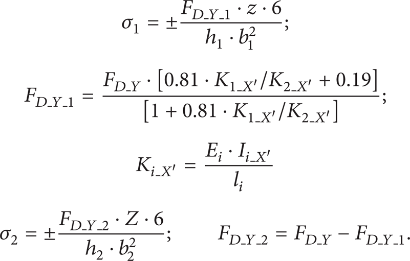
Analysing the deflection induced by F D Y and acting in the plane Y-Z of the mounts, the distribution of force on both mounts is the first element to be considered. The force and, consequently, the bending moment can still be subdivided depending on the bending stiffness. However, the traditional calculation of load distribution, based on parallel mechanical stiffness [9] previously used for flexure in plane X-Y, is no longer valid. In fact, the ratio between the forces acting on both elements (FD Y 1/FD Y 2) is not equal to the ratio between the bending stiffness (K1 X′/K2 X′) compared with the barycentre axis X′ of the elements but is proportional to that ratio as shown by numerical analyses whose results are reported in Figure 9. Thus it is necessary to introduce a linear relation that links the ratio of forces to the ratio of stiffness. Making a system with the linear relation shown in Figure 9 and with the equilibrium condition stating that FD Y 1 + FD Y 2 = F D Y , it is possible to calculate the load acting on the longer mount and that acting on the shorter one. Of course, if both mounts have the same stiffness (K1 X′/K2 X′ = 1) the force would be equally distributed on both of them. In this case the maximum stress is calculated by (7) as follows:
Therefore, the magnitude of the bending moments in plane Y-Z due to F D Y located at distance z from the average plane of the mounts is FD Y 1 · z and FD Y 2 · z, for mount 1 and 2, respectively. If the mounts have a different length, the bending moments generate deflection displacements on the two different ends, which are rigidly connected to each other by the brake caliper. This involves the presence of a secondary torsion applied in order to keep the external surfaces of mounts aligned on the same plane. The magnitude of the present torsion component is basically proportional to the difference in height of the two mounts. Moreover, the torsion on components having a rectangular section produces the deformation (buckling) of the sections so that they do not remain flat and smooth after the rotation but will tend to buckle as shown on the left of Figure 10. The presence of the stanchion at the base of the mount prevents the buckling [10] but generates a normal stress on the mounts. This buckling phenomenon is the reason because stresses, which should be theoretically constant on the sides of the mounts in absence of torsion, are not constant (right of Figure 10). Furthermore, the coupling produced between mechanical components, whatever the production process, generates a stress concentration factor [11–13]. The is stress value calculated via (7) is obtained in the middle of the side where the buckling of the section is permitted, whereas higher and lower values are obtained at the ends (the avoided and the stress concentration factor generate stresses with the same magnitude having equal and opposite direction compared with the bending directions): the trend of stresses along the side face is therefore linear. In order to take into account this linear distribution coefficient, α (8) was introduced, which allows correcting the stresses calculated via (7). The α coefficient is expressed depending on the difference in height of the mounts Δl = l1 – l2 (in the case of equal heights, α = 0 since there is no secondary torsion) and it has been determined by performing about 50 numerical analyses as

Comments and investigations which bring to (8) justify the nonconstant trend of stresses on the side of the mounts, even if the variation introduced by coefficient α is moderate considering the common differences in height (maximum ± 10% compared with the medium value).
Distribution of forces on both mounts for the deflection on the plane Y-Z of the mounts.

Buckling phenomenon on a rectangular beam section subjected to torsion and numerical analysis of the deflection acting on plane Y-Z of the mounts.
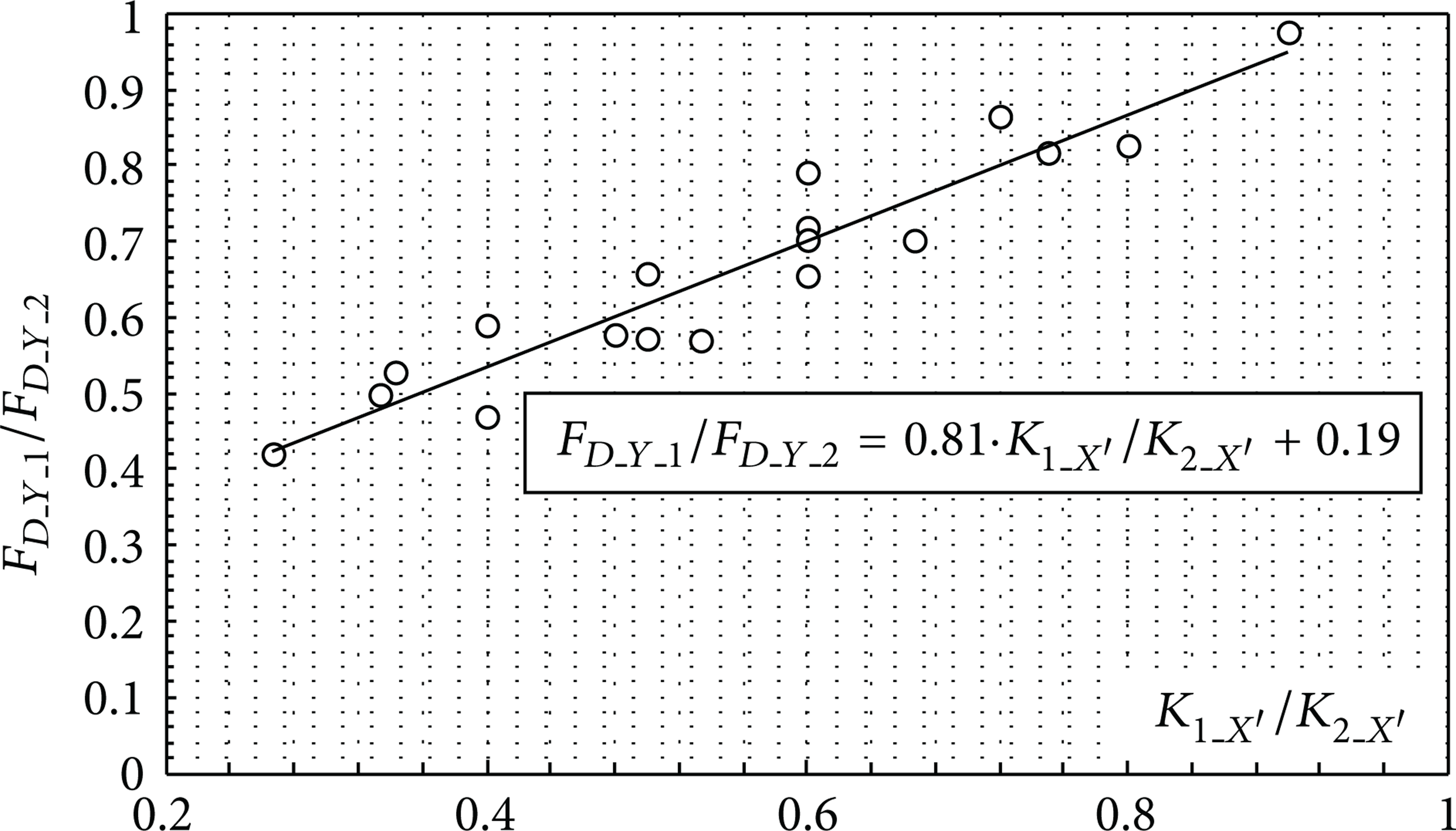
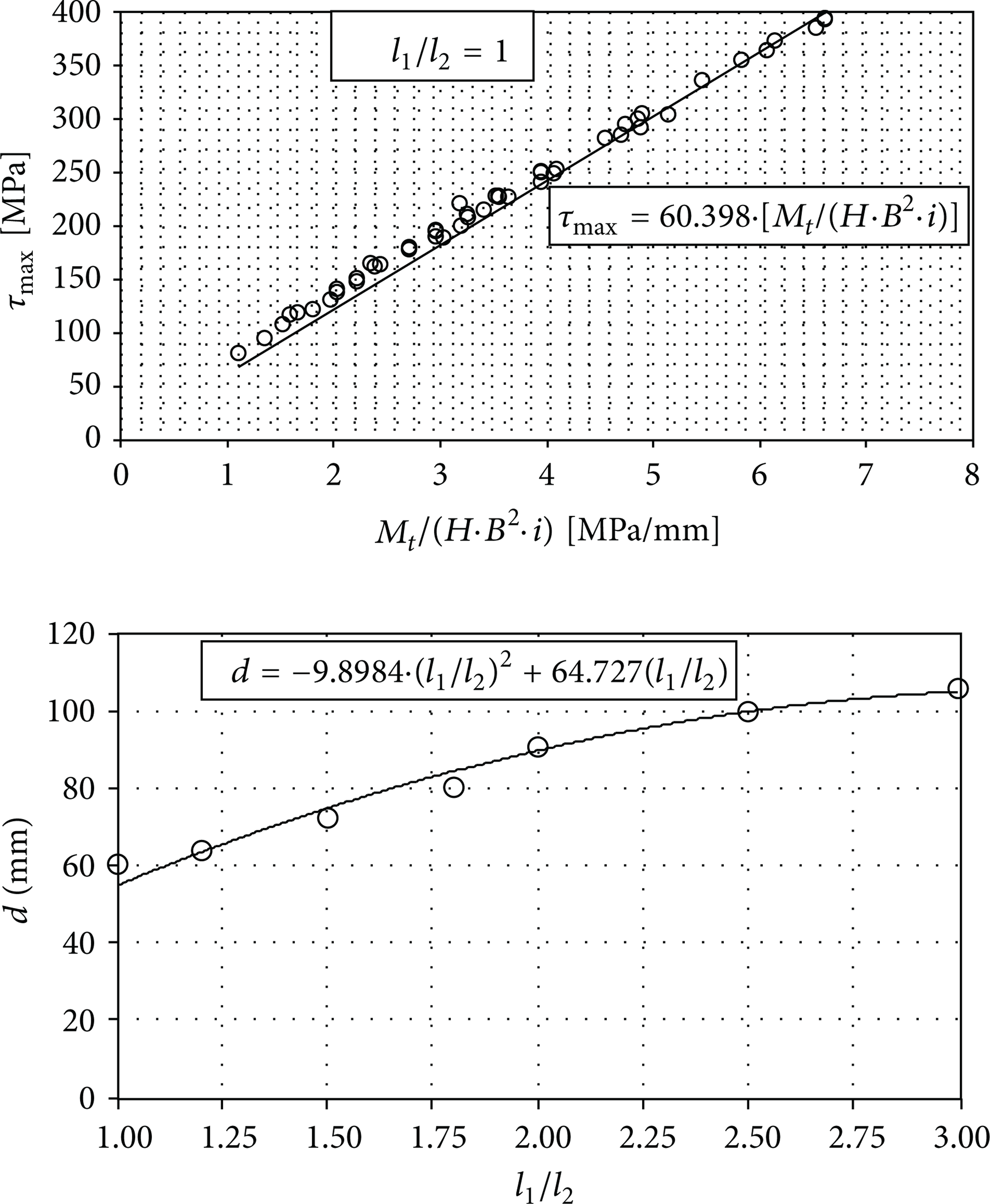
The last stress acting on the mounts is the torsion acting on the plane X-Z due to the application of F D X at a distance z from the average plane of the mounts. The calculation of the stresses produced by the present torsion brings to the highest discrepancies if calculated via theoretical De Saint Venant formulae and models mainly caused by the rectangular section and by the hyperstaticity of the connection applied to a short (stocky) beam. The numerical analyses have shown that the maximum tangential stress always occurs on the shorter mount (the stiffer one), on the longer side and located at the corner due to the avoided buckling. FEM analyses have been performed for different values of h1,2, of b1,2, of the distance i between the centres of the mounts and of the heights of the mounts. The nondimensional ratios have been kept as follows: h/b = [1; 2], i/h = [1; 3], and l1/l2 = [1; 3]. The ranges of the basic parameters have been chosen based on the most frequent dimension of caliper mounts produced by motorbike companies. The analysis of the results produced by the torsion effect led to the expression of the maximum torque stress τmax as a function of the applied moment, of the section properties, and of the distance between centres of the mounts, as indicated in (9). In this equation, the value of dimensionless coefficient η, which is the correction factor used in beams with a rectangular section subjected to torsional moment [9], depends on the distance between centres of mounts i and on parameter d. The parameter d can be expressed as a function of the difference in height of the mounts and can be determined once the angular coefficient of lines represented, for instance, by (9) for a given value of ratio l1/l2, are known. The first diagram of Figure 11 shows an example of such lines obtained in the case of equal length, whereas all values d obtained for different heights are shown in the second diagram.
Diagrams useful for τmax calculation in the case of mounts with the same height or with different heights.
The parameter d, necessary to calculate τmax, has been defined for each of the 7 different values of ratio l1/l2, through various combinations of about 50 geometries as follows:
Finally, by applying the principle of effect superposition, the maximum stress is obtained on the farthest corner of the shorter mount, with respect to the application point of the load, by summing all the contributions given by (4), (6), (8), and (9). The contributions of (4), (6), and (8) must be, of course, algebraically summed since they are normal stresses, whereas the contribution of (9), being a tangential stress, must be combined with the result of the previous sum in order to obtain the ideal stress, for example, according to Von Mises.
An example of the application of the proposed calculation method is shown in Table 1. The values refer to a geometry currently produced. Figure 12 contains the load and constraints scheme and the equivalent stress according to Von Mises criterion, obtained by the FEM analyses. The maximum stress calculated by applying the present model in the point highlighted in Figure 12, namely, on mount 2 (the shorter one), where the positive stresses induced by bending on the two planes have the same direction (positive) and only the normal stress has opposite direction (negative), is equal to 121 MPa. The stress resulting from the simulation is equal to 127 MPa; therefore, the error obtained is equal to 5%.
Example of the application of the proposed calculation method and comparison with FEM results.


Load, constraints, and equivalent stress according to Von Mises in traditional caliper mounts.
2.3. Experimental Test Equipment
The proposed model is able to effectively estimate the maximum stress acting on the caliper mounts and produced by the braking force, with errors always lower than 15% compared with the values provided by the numerical analysis. In order to validate the theoretical model and to carry out some experimental tests according to the test specifications, a standard experimental equipment, shown in Figure 13, has been specifically designed and manufactured by the authors in order to test different caliper mounts with one or both stanchions installed. The central plate, installed in the actual position in order to limit the bending moment on the fixed-end support, is directly connected to the load cell of the standing press, which supplies the force F R as indicated in Figure 4. The brake caliper mounts are connected via their own bolts, as shown in Figure 13, to an intermediate plate which is, itself, connected to the main plate via a spacer and two pins located at the ideal contact points between the disc and the pads, in order to simulate the transmission of force F D . Both the traditional and the radial mounts have been tested. Some strain gauges have been applied to them in order to obtain the local deformation and consequently the stress value. The numerical (FEM) analyses performed on the same structure as shown in Figure 14 returned results, which are perfectly aligned with the value measured by the strain gauges. In Figures 13, 14, and 15 some images are collected concerning the numerical and experimental analysis.

Test equipment for testing the brake caliper mounts.
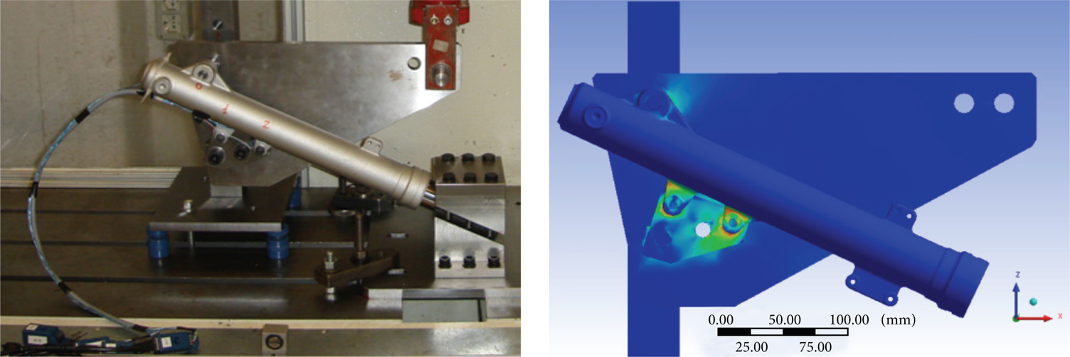
Picture of experimental tests and numerical simulations performed on standard brake caliper mounts.

Picture of experimental tests and numerical simulations performed on radial caliper mounts.
3. Conclusions
The present work analysed the forces, the stresses, and the deformations acting on brake caliper mounts of front motorbike suspensions and induced while motorbike is braking in a rectilinear motion at the vehicle's capsizing limit. Firstly, a useful theoretical model has been studied and proposed in order to evaluate the maximum braking force to be imposed to the caliper mounts based on the vehicle's characteristics (total mass, barycentre position, tire, and brake disc size). Some calculation formulae have been also defined and verified after having executed over 700 numerical (FEM) analyses made on the simplified sketch of the mounts, in order to overcome the problems of calculation related to the hyperstaticity of constraints and to the shape and geometry of components. Finally, standard equipment useful to carry out experimental tests on the brake caliper mounts has been specifically designed and manufactured by the authors. This kind of equipment can be easily and quickly used to perform tests that involve only the parts of suspension (stanchion or axle bracket) that are linked to the caliper mounts. The experimental tests were also used to validate the proposed theoretical model, which produces errors always lower than 15%.
Conflict of Interests
In the present paper, some structural analyses have been performed using the FEA modeller Ansys R11 software, which is regularly licensed to the University of Bologna. The use of Ansys R11 software must be regarded as an authorized academic use; therefore, the authors (Dario Croccolo, Massimiliano De Agostinis, Giorgio Olmi, and Alessio Tizzanini) declare that they have no conflict of interests with the ANSYS Inc. or any financial gain related to the publication of this paper.