
Abstract
A mesh regeneration method was put forward, and its application on the jig-shape optimization design of a high-aspect-ratio wing was carried out in the present study. In the mesh regeneration method, some control lines were selected based on configuration characters of the wing structure firstly. And then a new aerodynamic model was built according to the new control lines distribution which always keeps the same outline. Finally, mesh generation and quality optimization were carried out. Three different jig-shape optimizations based on mesh regeneration method were carried out on a high-aspect-ratio wing. All of them can obtain the designed jig-shapes which have excellent agreement with the expectant one under the impact of static aeroelasticity. Lift coefficients of all the three jig-shape optimization were larger than that of the original flat wing. The results of integrated jig-shape optimization which considered both flexure and torsion were not as well as those in their own independent optimization. An appropriate jig-shape optimization method needs to be selected according to the practical high-aspect-ratio wing design.
1. Introduction
Transonic range cruise capability needs to be considered in the design of large transport airplane, high-speed bomber, and civil aircraft. The high-aspect-ratio wing structures are always adopted in these aircrafts. Stiffness of the high-aspect-ratio wing structure is generally low, which seriously affects aeroelasticity characters. Flying quality will decline due to elastic deformation of the aircraft. So jig-shape optimization design, which is used to eliminating the influence of aeroelasticity on load distribution and configuration of the wing structure, is necessary in the preliminary aircraft design, especially for the high-aspect-ratio wing.
Many scholars dedicated to research in the field of aeroelasticity analysis and optimization design. A lot of design methods and basic theories were put forward. As early as in 1990s, Sherift et al. [1] had begun to research aircraft static aeroelasticity and jig-shape optimization design based on N-S equation. Hansen and Horst [2] regarded the choice of an appropriate design as an optimization problem and solved by the application of a multilevel optimization procedures based on detailed Finite Element models of certain structural parts. T.-L. Ma and D.-L. Ma [3] expatiated on the relationship between multidisciplinary design optimization for aircrafts and the large-scale system theory. Alonso et al. [4] described briefly a set of procedure for the optimization design of full mission aerospace systems which involves multiphysics simulations at various fidelity levels, surrogates, distributed computing, and multiobjective optimization. Chintapalli et al. [5] presented a methodology for the design optimization of a skin-stringer panel of an aircraft wing box. Oktay et al. [6] presented a set of structural optimization tools for topology optimization of aircraft wing structures coupled with Computational Fluid Dynamics analyses. At the same time, a series of configuration design tools was introduced, such as Generic Parameterized Aircraft Surface [7], RAGE [8] and RDS-Professional [9].
In solving Computational Fluid Dynamics (CFD)/Computational Structural Dynamics (CSD) coupling problem, computational zone changes over time and the corresponding regional grids need to be changed. There are two methods to change the mesh, they are mesh regeneration and dynamic mesh. Several methods in dynamic mesh were put forward and applied in the field of aeroelasticity analysis, such as Spring Analogy Method [10–12], Elastic Solid Method [13, 14], and Layered Elastic Solid Method [15]. A rather large deformation will be caused by the flexibility of high-aspect-ratio wing, which gives dynamic mesh a great challenge. Mesh regeneration method which rebuilds the mesh in computational zone is superior in dealing with the large deformation problem. A serious aeroelasticity problem will be caused due to the state of high-aspect-ratio design. It needs to be considered carefully in the preliminary aircraft design.
In the present study, mesh regeneration method and its application on aeroelasticity analysis of high-aspect-ratio wing were present. And then, three different jig-shape optimization methods, which consider flexure, torsion and both of them, respectively, were studied based on mesh regeneration method.
2. Mesh Regeneration Method
2.1. Mesh Regeneration
Usually, chordwise cross-section can be assumed to be rigid in aeroelasticity analysis of high-aspect-ratio wing. Flexure and torsion are the main influencing factors of aeroelasticity characteristics. So, geometric model, especially for some regular structures such as wing and blade, can be generated based on some special control lines of exterior surface. The selection of control lines has a direct influence on geometric model. So, control lines selected must have the capability of representing the geometric characteristics. A point-curve-surface order is used to build geometric model through stepwise, and the mesh is generated based on batch process automatically. Figure 1 shows the detailed mesh regeneration process. Structural nodes are adopted as the points used in control lines regeneration. The location of point is the sum of initial position and its displacement. So, structural deformation does not need to be transferred to aerodynamic analysis mesh as usual, which eliminates the error generated through conventional deformation information transfer.

Mesh regeneration process.
In the model regeneration of deformed wing structure, flexure and torsion of chordwise cross-section can be obtained through structural analysis. A new series of control lines is generated based on the new node coordinates, where the outlines remain unchanged. Computational zone selection and mesh regeneration are carried out on the deformed model automatically according to a certain process. It can be conveniently used in coupled solving problems which need mesh to be regenerated many times.
2.2. Mesh Quality Optimization
Batch processing treatment on mesh regeneration greatly facilitates the solving of some multistep coupling problems. But the batch processing mesh regeneration method cannot deal with local special parts well, especially for some sharp changed parts. Decline in mesh quality has a direct impact on computational precision. So, a mesh quality optimization treatment is necessary for the regenerated mesh.
Spring analogy method (SAM) can be well used in mesh quality optimization [16]. In SAM, the whole computational zone is regarded as a system composed of springs. Internal grids reach a new equilibrium according to the local condition when the boundary movement occurs. Vertex springs analogy method, in which the equilibrium length of spring is assumed to be zero, is one description of SAM. It can be better used in mesh quality optimization. In vertex spring analogy method, spring tension between internal grids of i and j can be expressed as

where K
ij
is the stiffness of spring between internal grids of i and j,

where N is the number of internal grids connected with i. The initial state of whole computational zone can be written as
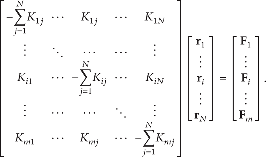
Some boundary constraints are added to (3), such as outer boundary maintains the initial position and inter-boundary changes to the new position. The iterative equation to be solved reads

Spring stiffness has an obvious influence on SAM [17]. The conventional spring stiffness can be expressed as

where l ij is the distance between internal grids of i and j. Collision between different internal grids can be well avoided through introducing l ij into the spring stiffness. However, the decline of mesh quality is still obvious when a large deformation occurs. Mesh quality control parameters, such as skewness and aspect ratio, are added to the conventional spring stiffness for optimizing some bad meshes. It can be found as

where q
s
= 1 – 3αmin/π and
2.3. Application on Aeroelasticity Analysis
Static aeroelasticity analysis is an iterative solving process. First of all, aerodynamic calculation of the initial wing model is carried out. The deformation under the function of aerodynamic load above is obtained through structural analysis. Then the mesh regeneration and optimization are adopted to build the new mesh for the next aerodynamic calculation. Under the function of message transfer, structural analysis is carried out again until both aerodynamic load distribution and deformation are convergent. Then static aeroelasticity parameters including aerodynamic and structural characteristics are obtained. Figure 2 shows computational process of coupled method based on mesh regeneration method. Flexure and torsion of the cross-section which is selected as one of the control lines can be obtained through structural analysis. The next aerodynamic model is regenerated based on the control lines after flexure and torsion processing.
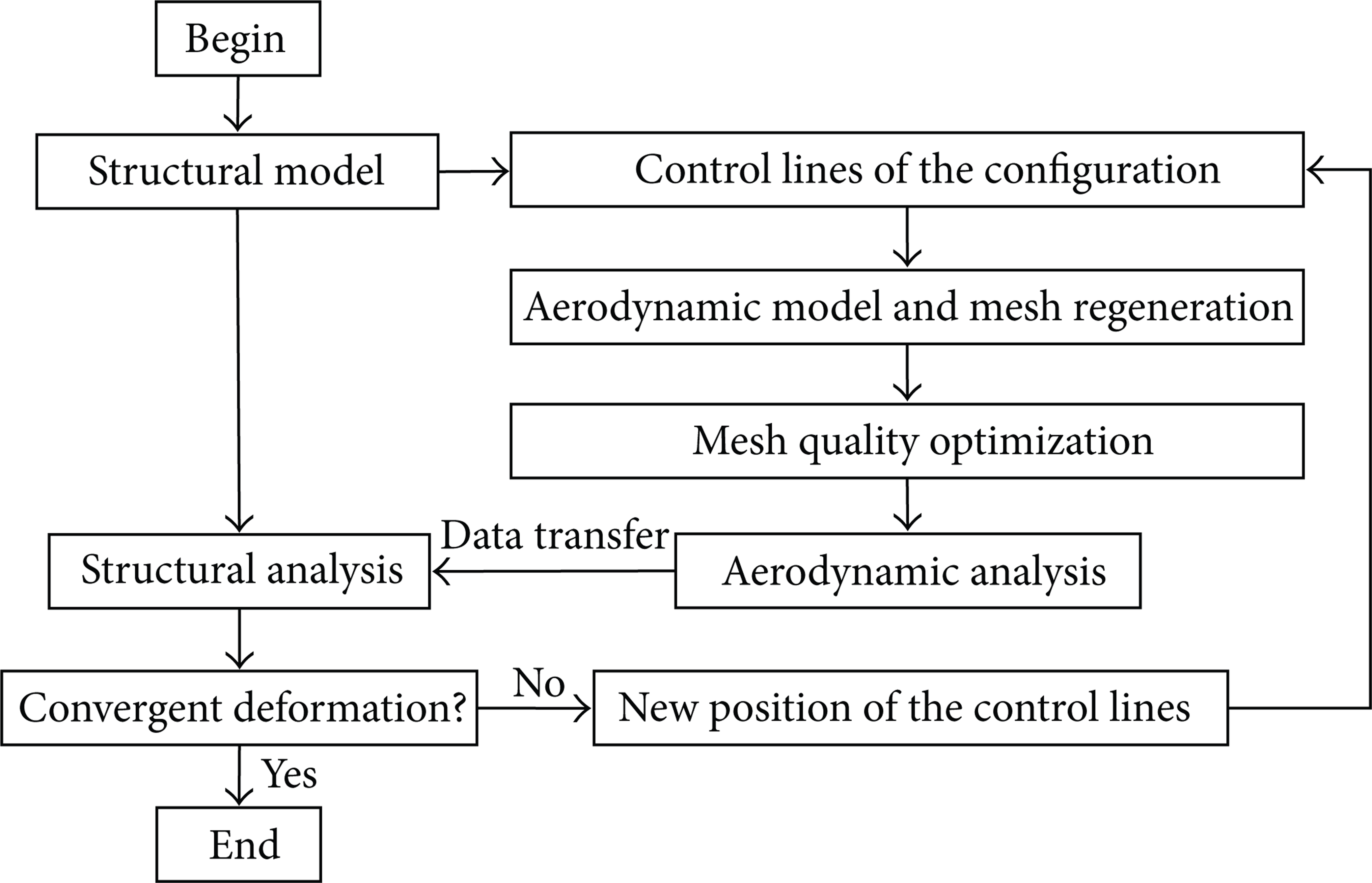
Computational process of coupled method.
Figure 3 shows finite element model of the high-aspect-ratio wing structure. The wing structure is mainly composed of skin, lengthwise and transverse components. Lengthwise components include spar and stringer while transverse components include rib and thin-walled jointed structure. All the components are made of aluminium alloy of LY12. Its Young's modulus is 66 GPa and Poisson's ratio is 0.33. The structural analysis is carried out through the software of NASTRAN which can consider the geometrical nonlinear well.
Finite element model of the high-aspect-ratio wing.
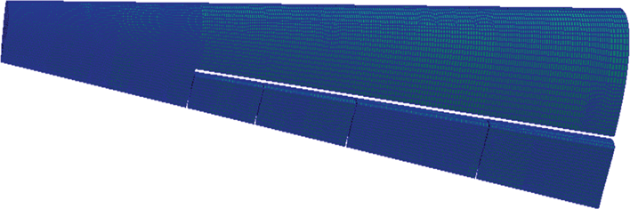
Figure 4 shows the aerodynamic model generated based on the control lines. As can be viewed from Figure 4, eleven cross-sections are selected to control the deformation of main wing structure, while five cross-sections are selected for the aileron. Control lines of the cross-section are adjusted based on the deformation of wing structure, and a new wing model is built based on them.

Aerodynamic model generated based on the control lines.
CFD software FLUENT is adopted for aerodynamic analysis while FEM software NASTRAN for structural analysis. Pressure distribution on the coupled surface can be obtained through aerodynamic analysis, but load for structural analysis often needs to be applied directly on structural nodes or elements. So load interpolation transfer is necessary. For every CFD node, three CSD nodes which can enclose it and have a minimal area are selected firstly. Load information of the CFD node is transferred to these three CSD nodes. It can be expressed as

where G x , G y , and G z are the three directions compression force obtained through CFD software FLUENT, Fx, i, Fy, i and Fz, i are load applied on structure. A i and A are area of two triangles, the former one is formed by one CFD node and two CSD nodes, while the latter one is formed by three CSD nodes. After the load interpolation transfer of all CFD nodes, the new load format for structural analysis can be obtained.
Static aeroelasticity is analyzed under the flight attitude of 15 Km altitude, Ma 0.5, and attack angle of 2°. After iterated twelve times, lift coefficient and deformation are convergent. Figures 5 and 6 show the iterative processes of lift coefficient and flexure, respectively. It can be seen that lift coefficient converges at 0.16 while flexure converges at 1700 mm. Both lift coefficient and flexure decreased under the impact of static aeroelasticity.

Iterative process of lift coefficient.

Iterative process of deformation.
Figures 7 and 8 present the flexure and torsion distribution of the cross-sections, respectively. As can be viewed from Figure 7, flexure of wing root which is restrained is 0 mm while wing tip has the maximum flexure of 1700 mm. Intermediate cross-sections deformed glossily. From Figure 8, it can be seen that torsion distribution of the cross-sections has the same trend, and the maximum torsion angle is 1.4°. Torsion of the cross-sections reduce practical attack angle, which leads to the decrease of lift.

Deformation distribution of the cross-section.
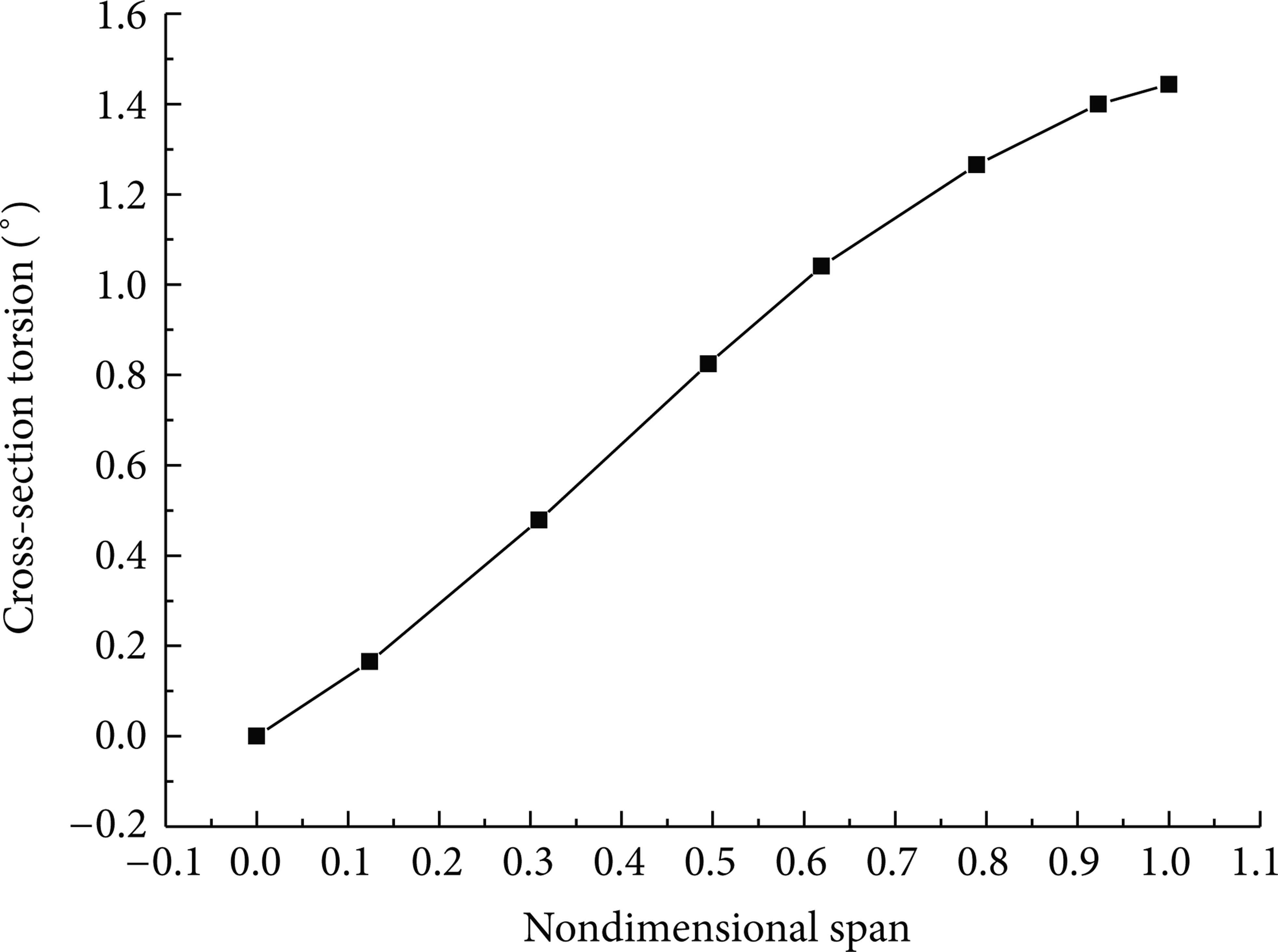
Torsion distribution of the cross-section.
3. Jig-Shape Optimization
Aerodynamic distribution and deformation are changed under the impact of static aeroelasticity. Along with them, jig-shape of the wing structure cannot keep its initial form. Jig shape optimization is a predesign. Its target is to obtain a designed jig-shape which will converge to the expectant one under the impact of static aeroelasticity. Figure 9 shows the jig-shape optimization process. As can be viewed from Figure 9, deformation of the wing structure can be divided into flexure and torsion distribution of the cross-sections. For one of the cross-sections of the high-aspect-ratio wing, which is denoted as the rth cross-section here, iterative deformation in jig-shape optimization can be expressed as

where X r n means the flexure or torsion of the rth cross-section before the n time iteration, Xe, r n expresses the change of flexure or torsion of the rth cross-section at the n time iteration, Xe, r is the expectant flexure or torsion of the rth cross-section, and ξ is a relaxation parameter placed between 0 and 1.0. After N times iteration, when the flexure or torsion meets (9), a jig-shape optimization result will be obtained.

Jig-shape optimization process.
Consider

where l is wingspan of the high-aspect-ratio wing ∊ is used to judge the convergence of the iteration and is 0.5% here.
The control lines always keep the same outline in the whole jig-shape optimization process, which is the basic assumption for every cross-section. According to the new flexure and torsion distribution, control line state of every cross-section is adjusted. And the new aerodynamic model is generated based on the new control lines. In the mesh regeneration method, the deformation of wing structure is seen as the control line state distribution. It is conducive to have an independent control of every cross-section in the whole jig-shape optimization process.
Three different optimization parameters are considered in the present study, they are flexure, torsion, and both of them. Static aeroelasticity results of the original wing, which can be seen in Figures 7 and 8, are set to initial values after a negative treatment.
3.1. Independent Flexure Optimization
In the independent flexure optimization, torsion of cross-section keeps the initial value during the whole optimization process. Figure 10 shows the results of independent flexure optimization. Only flexure distribution of cross-section is considered, and a flat wing is assumed to be the expectant jig-shape in the present study. Three different flexure distributions of the cross-section are present in Figure 10. They are expectant, designed, and convergent jig-shape, respectively. As can be viewed from Figure 10, excellent agreement between the convergent jig-shape and the expectant one is observed. The independent flexure optimization based on mesh regeneration method can be well used in jig-shape optimization when just flexure is considered. As can be viewed from designed jig-shape in Figure 10, a smoothly downward flexure distribution design can be convergent to a flat wing under the impact of static aeroelasticity.
Independent flexure optimization results.
3.2. Independent Torsion Optimization
In the independent torsion optimization, flexure of cross-section keeps the initial value during the whole optimization process. Figure 11 shows the results of independent torsion optimization. Only torsion distribution of cross-section is considered here, and the expectant jig-shape is assumed to be an attack angle of 2° in all of the cross-sections. Three different torsion distributions of the cross-section are present in Figure 11. They are expectant, designed, and convergent jig-shape, respectively. As can be viewed from Figure 11, excellent agreement between the convergent jig-shape and the expectant one is observed. The independent torsion optimization based on mesh regeneration method can be well used in jig-shape optimization when just torsion is considered. As can be viewed from designed jig-shape in Figure 11, a smoothly increased torsion distribution design can be convergent to the expectant jig-shape under the impact of static aeroelasticity.

Independent torsion optimization results.
3.3. The Integrated Jig-Shape Optimization
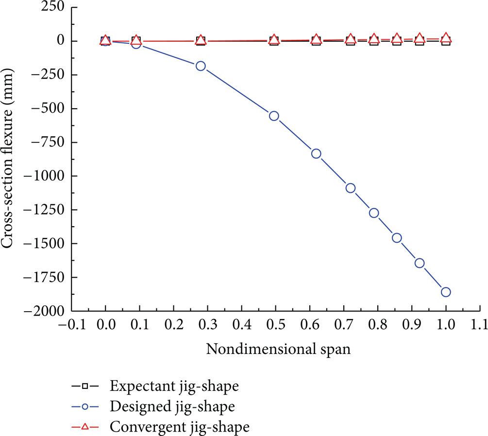
Both flexure and torsion distribution are considered in the integrated jig-shape optimization. Its expectant flexure and torsion distribution are assumed to be the same values as those in their own independent optimization above. Figures 12 and 13 show the integrated jig-shape optimization results, they are flexure and torsion distribution, respectively. Comparing the results in Figures 12 and 13 with those in Figures 10 and 11, it can be seen that both optimization results in integrated jig-shape optimization are similar with their own independent results. The slight difference is that the error between convergent jig-shape and expectant one are larger than those in their own independent optimization. But the errors are still in an acceptable range for a wing structure design. The integrated jig-shape optimization based on mesh regeneration method can be well used in jig-shape optimization when both flexure and torsion are considered.

Flexure results of the integrated jig-shape optimization.
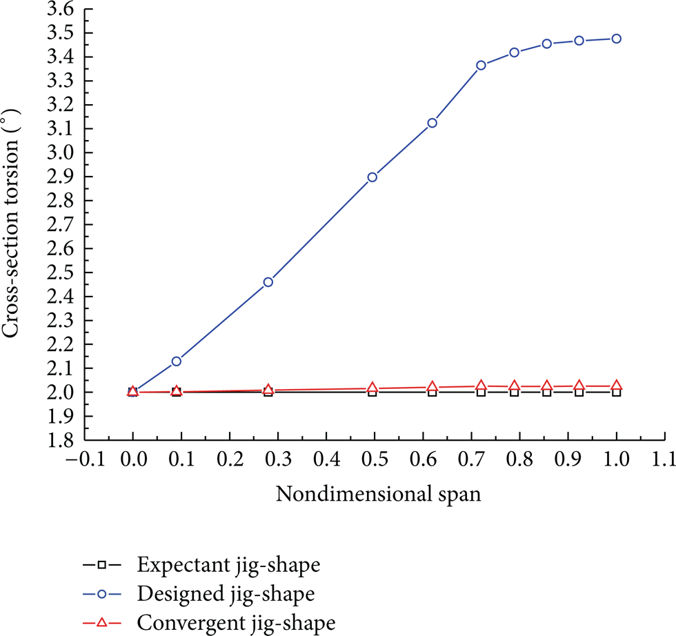
Torsion results of the integrated jig-shape optimization.
3.4. Comparison of Different Optimization Methods
Figure 14 shows lift coefficient iterative processes of different jig-shape wings in static aeroelasticity analysis. It can be seen that the convergent lift coefficients of torsion and integrated jig-shape optimization have the similar value and are larger than those of flexure jig-shape optimization and the original flat wing. Lift coefficient of the wing structure after flexure jig-shape optimization is larger than that of original flat wing too, but the incremental value is less than those of other two optimization methods. In the high-aspect-ratio wing design, the effect of torsion, which has an obvious influence on attack angle, on lift coefficient is still dominant. Flexure along with span also affects the lift coefficient, but it is not as obvious as torsion.

Lifts coefficient iterative processes of different jig-shape wings.
All the three jig-shape optimization methods can obtain the expectant jig-shape wing structure and their convergent lift coefficients are larger than that of original flat wing. The results of integrated jig-shape optimization method are not as well as those in their own independent optimization. But both flexure and torsion are considered and its convergent lift coefficient can obtain a larger value. So, it is needed to select one of the jig-shape optimization methods based on practical high-aspect-ratio wing design.
4. Conclusions
A mesh regeneration method and its application on static aeroelasticity analysis and jig-shape optimization design were put forward in the present study. Some useful conclusions can be drawn.
A mesh regeneration method which contains mesh regeneration and mesh quality optimization was put forward in the present study. An automatic mesh regeneration and mesh quality optimization based on control lines was carried out on a high-aspect-ratio wing.
Static aeroelasticity of a high-aspect-ratio wing was analyzed based on mesh regeneration method. It can be well used in dynamic mesh application, especially for a large deformation.
Three different jig-shape optimizations based on mesh regeneration method were carried out on a high-aspect-ratio wing. All of them can obtain the designed jig-shapes which have excellent agreement with the expectant ones under the impact of static aeroelasticity.
Lift coefficients of all the three jig-shape optimization were larger than that of original flat wing. The results of integrated jig-shape optimization which considered both flexure and torsion were not as well as those in their own independent optimization. An appropriate jig-shape optimization method needs to be selected according to the practical high-aspect-ratio wing design.
Footnotes
Acknowledgments
This study is supported by the National Natural Science Foundation of China (no. 51175424) and Shaanxi Provincial Natural Science Foundation (no. 2009JQ1006).