
Abstract
We propose an Underwater Wireless Sensor Network (UWSN) for near-shore applications using electromagnetic waves (EM). We also introduce a realistic path loss model for estimating the attenuation encountered by EM waves in underwater environments. The proposed model takes into account the variation of the seawater complex-valued relative permittivity with frequency in contrast to previous work that treats the permittivity as a real-valued constant parameter. Furthermore, the proposed model accounts for the impedance mismatch at the seawater-air boundary, which results in a more realistic estimate of the signal attenuation. Simulation results show the expected signal levels underwater for different scenarios. A prototype implementation to measure the path loss is also presented.
1. Introduction
There has been a great interest in developing underwater wireless communication systems using electromagnetic waves such as Underwater Wireless Sensor Networks (UWSNs). Such networks could be used for monitoring near-shore variations in seawater, coastal surveillance, autonomous underwater vehicle (AUV) operations, environmental research, and so forth [1]. The interest in EM underwater communications is motivated by several features such as the support of high data rates, and the low propagation delay. This will reduce the transmission duration, which will reduce the power consumption, and consequently it will prolong the lifetime of the nodes [2]. Also, EM waves are insensitive to the disturbances in the physical environment [1]. Moreover, the sensor nodes have become affordable in very large quantities as well as being self-operated. They can be randomly deployed over the region of interest (e.g., scattered by an airplane over a hostile environment). These advantages incur low installation and maintenance cost compared to the existing communication systems.
Acoustic waves, on the other hand, remain the prevalent existing underwater communication mechanism in deep aquatic environments since they can propagate for longer distances. However, for near-shore applications, significant human activities and ambient noise severely affect underwater acoustic communication systems (e.g., congested environments like harbours and ports). In addition, underwater acoustic channels are characterized by the harsh physical layer conditions, which result in low data rate capabilities, high propagation delay, and high bit error rate (BER). For instance, sound waves use very low frequencies for signal transmission, and thus have very limited bandwidth, which results in very low data rates. In addition, with a propagation speed of 1500 m/s, sound waves cause a significant delay in signal transmission. These aforementioned challenges limit the possible applications provided by acoustic systems. That is, it is impractical to implement acoustic systems for both near-shore applications and real-time applications [3].
To overcome the problems faced by acoustic wave based systems, cables are commonly deployed for reliable transmission near the shore. However, cable-based systems suffer from high cost of installation and frequent need of calibration and maintenance. Other solutions based on optical communications have also been proposed such as AquaOptical in [4] where several optical modems are developed for point-to-point communications underwater. However, the long-range modem is currently very expensive (it costs around US$1,200), and thus it is implausible to implement for large-scale networks. A cheaper short-range modem is also developed, but it covers few meters and as well it has worse performance in terms of signal detection. Finally, it is observed in [4] that the turbidity of seawater severely limits the achievable data rates. In general, optical communication systems suffer from the need for accurate alignment between the optical transmitter and receiver, they are susceptible to particles and marine fouling (i.e., turbidity of seawater), and optical waves do not smoothly cross seawater-air boundary [1].
EM waves outperform both acoustic and optical waves in shallow water applications as they tolerate ambient noise, turbidity, and temperature changes. Furthermore, EM waves allow for much lower propagation delay and higher data rates (Mbps range) as compared to acoustic waves. These features support real-time applications where different forms of data could be transmitted (text, images, and videos), and hence new horizons for underwater applications become possible. For instance, UWSN could be deployed for AUVs where robots could get faster commands from the base station. It could be used for coastal surveillance where cameras could be distributed all over the shore at certain depths to monitor human activities, marine life, or any physical phenomenon. Other applications include monitoring of coastal erosion; prediction of natural disasters; and many other real-time applications that require high data rates. In addition, these sensors could be implemented as body area networks for divers to monitor their health, oxygen level, equipment, and so forth. All these features motivate the use of EM waves for both near-shore applications and real-time applications. Table 1 provides a brief comparison of the different underwater wireless communication systems.
A Comparison between different underwater transmission media.

The idea of underwater EM wave communications was envisioned since the 1950s, where researchers were interested in using radio for submarine communications, but it was abandoned because of the limited communication range due to the very high conductivity in seawater [5]. Nevertheless, the recent advancements in electronics and the affordable cost of wireless sensor networks have triggered a new interest in using EM waves for underwater applications. Several experiments for UWSNs have recently been implemented in [6] to compare different topologies for underwater networks and to obtain experimental data for signal attenuation at different operating frequencies. In addition, Al-Shamma'a et al. present in [6] a very simple attenuation model as a function of frequency. In [7], a channel model for freshwater environment is proposed. We remark that the results in [7] are not applicable for the more practical scenario in seawater applications because of the relatively low salinity of freshwater compared to that of seawater. In [2], Uribe and Grote present a simple analytical model based on Maxwell's equations. However, the model is merely for the attenuation loss due to seawater conductivity (i.e., the reflection loss at the seawater-air boundary is not considered), and it assumes a fixed value of seawater permittivity. To the best of our knowledge, there has been no other path loss models developed for EM waves propagating in seawater and most of the channel models for underwater communications are developed for acoustic waves.
In this paper, we propose a UWSN for near-shore applications. We introduce a more realistic path loss model for EM waves propagating in seawater that considers both the variation of the seawater complex-valued relative permittivity with frequency and the impedance mismatch at the seawater-air boundary. The rest of this paper is organized as follows. Section 2 describes the proposed UWSN structure. Section 3 outlines the electric properties of seawater and their impact on the propagation of EM waves. The proposed underwater path loss model is developed in Section 4. Simulation and experimental results are presented in Section 5. Finally, conclusions are summarized in Section 6.
2. Proposed UWSN Description
The architecture of the proposed UWSN is shown in Figure 1. It is composed of different nodes that communicate using EM waves to send information from sensor nodes to a sink node through one or more intermediate nodes. The sensor nodes might be anchored at the seabed to collect application-specific data or could be moving, as the case for AUVs. The data is then transmitted to the intermediate nodes that are scattered in the coverage area of the UWSN. The intermediate nodes need to be anchored at different locations and heights within the area of interest. They receive the EM signal, amplify it, and then retransmit it again to other intermediate nodes. Finally, a buoy node receives the signal at the seawater surface and forwards it to the sink node. The block diagram of the system is shown in Figure 2.

The network structure of one of the proposed schemes (Scheme II).

A detailed block diagram for the overall system.
The number and distances between intermediate nodes depend on the attenuation faced by the EM waves as they propagate through seawater. To cover the same area of interest, more nodes are required when using EM waves compared to acoustic waves (i.e., higher node density). This is due to the signal attenuation, which depends on the electric properties of seawater. Another important factor that also affects signal attenuation is the implementation of the buoy node. We consider two schemes for the buoy node design.
Scheme I uses one antenna at the buoy node that is not immersed in seawater, and hence the signal needs to cross the seawater-air boundary to be received by the buoy node. This results in significant attenuation of the signal, and hence needs more amplification at the intermediate nodes. To alleviate such a problem, Scheme II uses a buoy node with two antennas. The first antenna is immersed in seawater, and thus it receives the signal underwater from the intermediate nodes. Then, the buoy node amplifies the signal and then retransmits it to the sink through the second antenna, which is implemented above seawater. Scheme II provides for less attenuation, and therefore it is preferred to implement. All of these observations are going to be discussed in details in the next sections.
3. Electric Properties of Seawater
The propagation of EM waves in seawater is significantly different from that on air because seawater has distinct electrical properties that severely impact the signal propagation. Thus, in order to develop a realistic path loss model for EM wave propagation in seawater, these properties need to be discussed.
3.1. Conductivity
The conductivity of a medium affects the transmission of an EM wave through that medium. Specifically, the transmitted signal will face more attenuation as the conductivity of the medium increases. Seawater has high conductivity that varies depending on the presence of ions in it. For instance, the conductivity of Red Sea is 8 S/m whereas it is only 2 S/m in the Arctic. For typical seawater, it is common standard to use a value of 4 S/m for seawater conductivity [5, 8, 9]. This is 400 times higher than the conductivity of freshwater, which is typically around 0.01 S/m [7].
3.2. Permeability and Permittivity
Permeability is the ability of the medium to store magnetic energy. Since seawater is a nonmagnetic medium, it has the same permeability as free space,

The real dielectric constant of seawater (salinity= 35 PSU).

The imaginary dielectric constant of seawater (salinity = 35 PSU).
3.3. The Intrinsic Impedance
The intrinsic impedance is a medium property that describes the ratio of the electric field strength 

Seawater intrinsic impedance with frequency variations.
The reflection coefficient is expressed as [8]


The reflection and transmission coefficients for seawater are demonstrated in Figure 6. Note that we have

Magnitude of transmission and reflection coefficients at seawater-air boundary.
4. Channel Model
For proper deployment of any wireless communication system, it is critical to have accurate channel characterization. Channel modeling provides important information about the received signal strength (i.e., path loss) and multipath structure. In terrestrial WSNs, with air as the propagation medium, numerous works have been done to develop realistic channel models. However, due to the aforementioned electric properties of seawater, direct relation between seawater and air cannot be established. Hence, we are motivated to propose a new model for the underwater channel.
Path loss is a fundamental parameter in characterizing the wireless channel. It represents the difference between the transmitted signal power and the received signal power [14]. Path loss represents a large-scale channel modeling because, in terrestrial wireless systems, it is observed for large distances (hundreds of wavelengths). However, in the proposed underwater network structure, the distances between the nodes are expected to be very small (few meters), but the path loss underwater would be comparable with the path loss of hundreds of meters in air as we will demonstrate in this section. The path loss considered in this work is expressed in dB as [7]

In order to realize the impact of the complex permittivity on the attenuation factor, the attenuation loss is derived from the propagation constant γ, which is expressed as [8]


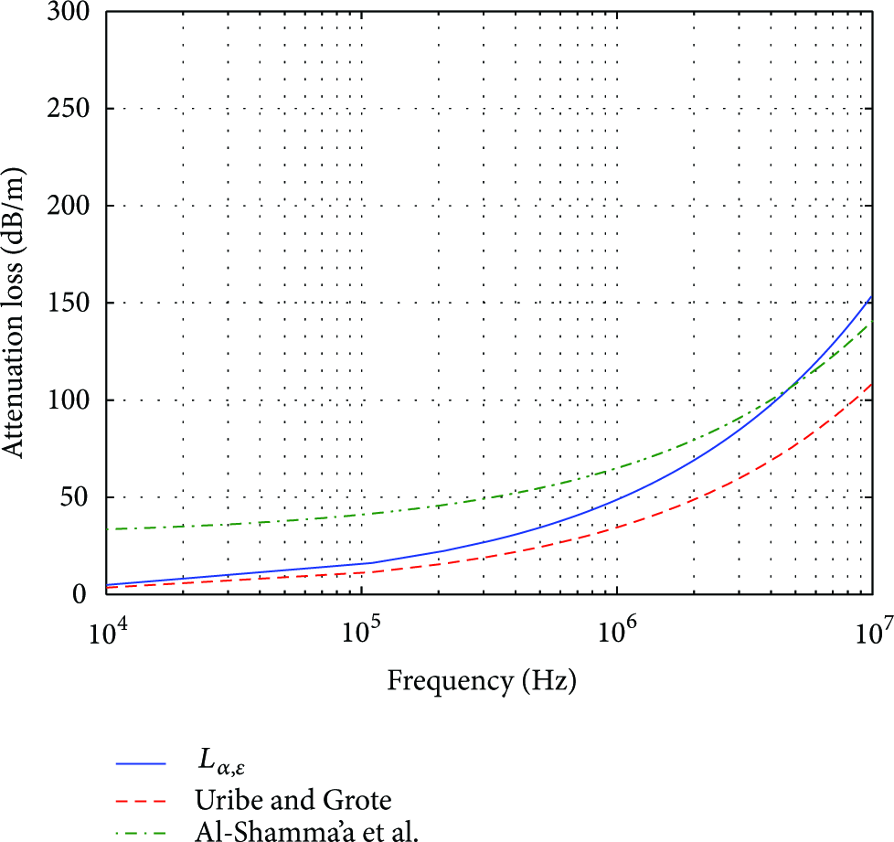
Attenuation loss with frequency variations.
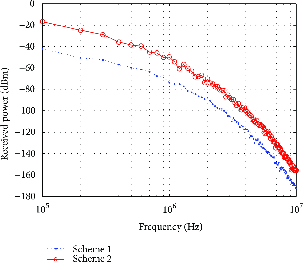
On the other hand, signal reflection due to impedance mismatch has a major impact on the EM wave propagation between different mediums. Impedance matching is very important to minimize the reflection at the boundary and maximize power transfer [8]. Since we have identified a mismatch in intrinsic impedance between seawater and air, a high-signal reflection at the boundary is expected. The transmitted power can be written as [7]


We remark that (9) assumes a direct link between the sensor node underwater and the buoy node at the surface. In case there is a relay (i.e., intermediate node) in between, then careful changes must be made. Figure 8 illustrates the high-signal attenuation at the seawater-air boundary. It shows that the reflection loss decreases dramatically as the frequency increases from 100 KHz to 1 GHz, and then it remains almost constant for frequencies higher than 2 GHz. This could be explained by noting that the magnitude of the intrinsic impedance of seawater is directly proportional to the carrier frequency; that is, as the frequency increases the impedance of seawater increases as shown in Figure 5, and hence the gap between the impedance of seawater and air decreases, which will ultimately reduce the reflection losses at the boundary. However, Figure 5 indicates that the impedance of seawater converges to a constant value for further increase in the operating frequency, and hence the reflection loss would be approximately constant at those frequencies (

Reflection loss with variations of frequency.
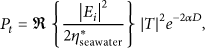
Total path loss with frequency variations at different depths.
Finally, a comparison between our model and the model presented in [7] is demonstrated in Figure 10. Both models implement Debye's models for seawater and freshwater, respectively. It is observed that the high conductivity of seawater drastically increases the path loss.

Total path loss comparison between seawater and freshwater.
5. Simulation and Experimental Results
In this section, MATLAB simulations are presented for the path loss and bit error rate (BER) for the proposed UWSN. We assume that the sensor node is located at the seabed, and the signal is sent directly to the buoy node located at the surface of the water. The buoy node detects the transmitted data and then retransmits it again to the sink node. Both cases for a buoy node with nonimmersed antenna (scheme I) and immersed antenna (scheme II) are simulated. Without loss of generality, Quadrature Phase Shift Keying (QPSK) is used as the modulation scheme with square root-raised cosine pulse shape. The QPSK signal is then transmitted through a channel with a path loss according to the model developed in (9). The signal is also assumed to undergo flat fading with Rician distribution since there are generally no obstacles between the transmitter and receiver. The channel is also assumed to have very slow variation with time (low Doppler) since the mobility of the nodes is limited. The movement of the nodes could be caused by the dynamic underwater environment such as the water current or the movement of surrounding objects. Using the data provided by Dubai Coastal Zone Monitoring, the maximum current speed is approximately equal to 0.2 m/s [13]. The Doppler shift is expressed as [14]


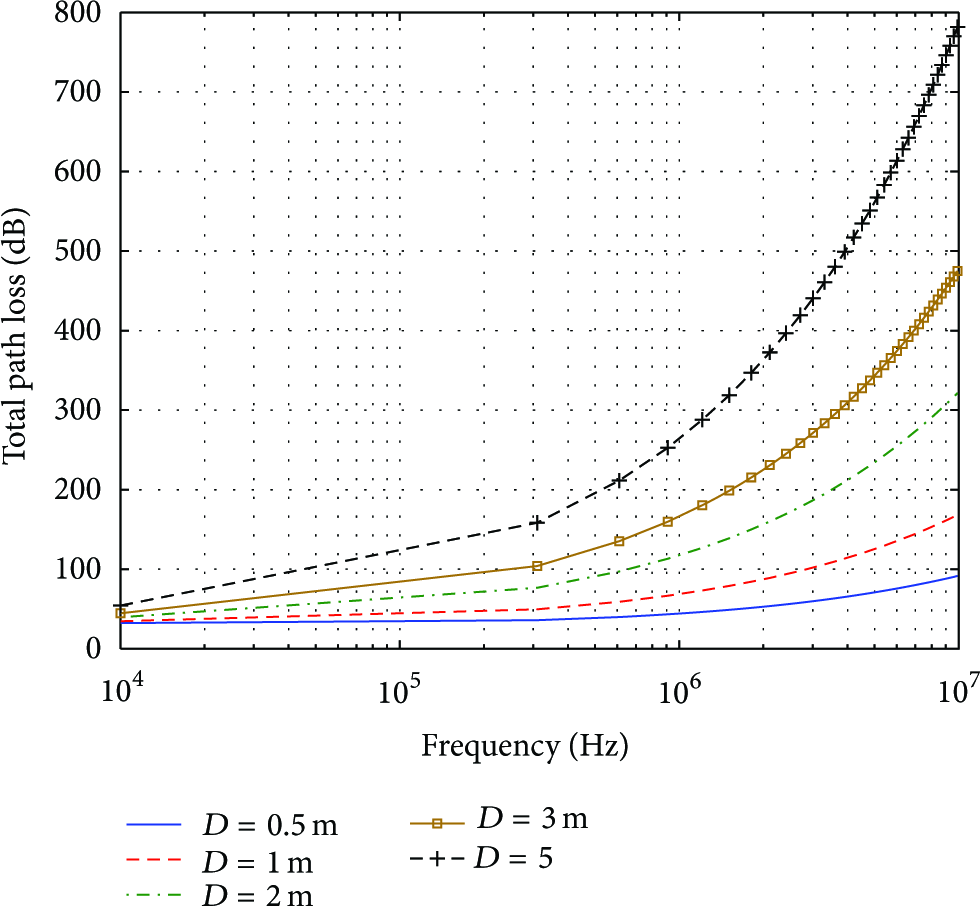
Figure 11 illustrates the received signal power for the two schemes for a transmitter at a depth of 1 meter, and a transmitted power of 0 dBm. It is clear that using an immersed antenna at the buoy node significantly reduces the signal power loss. This could be exploited either to increase the distance between nodes or use a higher operating frequency to achieve higher data rates. The improvement in the performance is mainly due to the elimination of the reflection losses at the seawater-air boundary. Table 2 compares the path loss of the two proposed schemes at different frequencies. The path loss gap between the two schemes decreases as the frequency increases because the reflection losses decrease at higher frequencies. Nonetheless, it is evident that at any given operating frequency, Scheme II is more power efficient. This is very crucial since power management is one of the major challenges in UWSN design, and hence by just making the receiver antenna of the buoy node immersed in seawater, we may prolong the battery life of the nodes, which in return, will reduce the regular maintenance and the battery replacement process. On the other hand, if we decide to send power at the same level, we can further increase the separation distance between the nodes (depending on the receiver sensitivity), which in return, will either expand the communication range, or reduce the number of nodes required to cover the same coverage area. Figure 12 shows the BER performance for the system with immersed antenna case. The result shows that the BER improves as the energy per bit-to-noise power ratio (
Path loss comparison between the two schemes.

The estimated received power of the proposed schemes.

The simulated BER of the underwater channel.
Finally, we have implemented a prototype to measure the path loss for the two schemes. A

The path loss of the two implemented schemes.
The results confirm that the path loss of the external receiver antenna is higher than the one with the immersed antenna. This is due to the reflection at the surface as suggested earlier. It is also clear that as the frequency increases, the path loss increases in agreement with the simulation results. We remark that our experimental results cannot be compared directly with the simulation results for the following reasons. First, the range of frequencies used is not precisely within the available antennas' operational range. Second, we have mixed a portion of freshwater with seawater, which in return will affect the salinity of the medium. Third, the temperature of the medium is different. We assumed a temperature of 25∘C in the simulations. Nevertheless, the experiment provides insights on the importance of implementing an immersed antenna at the buoy node. It is clear from the experimental results that immersing the antenna significantly reduces the path loss (up to 20 dB which is also demonstrated in the simulation results). Another insight is that at higher frequencies, the gap between Scheme I and Scheme II reduces because the reflection loss is also decreased. This reduction is due to the fact that the intrinsic impedance of seawater increases as the frequency increases. Thus, the mismatch of impedances between seawater and air decreases. This is what we have also demonstrated theoretically and in the simulations.
6. Conclusion
In this paper, an underwater wireless sensor network using electromagnetic waves is proposed. A realistic model for the path loss underwater has been developed. The effect of the signal reflection at the seawater-air boundary has also been considered. Two schemes are proposed for the buoy node located at the surface of the water; one based on nonimmersed antenna and the other with immersed antenna. The proposed schemes are simulated under slow fading channel conditions, and both the path loss and bit error rate performance are presented. Finally, a prototype to measure the path loss is implemented.