
Abstract
Most sensors for structural testing and health monitoring are “point” sensors which strongly limit the ability to correct damage detection and structural assessment. In this paper, long-gauge FBG sensor which can sense the whole area within the gauge length is introduced. Bridge assessment and health monitoring with the microstrain distribution acquired by the distributed long-gauge FBG sensor are also studied. Experiments were conducted and application to a real prestressed box bridge was also implemented. Static and dynamic testing results show that distributed long-gage FBG sensing technique can obtain not only the global information such as bridge deflection and natural frequency, but also the local parameters such as strain and modal macrostrain to detect damage of the bridge. It shows that structural assessment and health monitoring based on the proposed technique have great potential in maintenance of civil engineering infrastructures.
1. Introduction
Bridges are the most important facilities for many cities and countries. These infrastructures provide the necessary communication and transportation conditions for the residence. However, progressive deterioration of the civil infrastructure begins once they are built and subjected to normal continuous and occasional excessive loading, or adverse environmental conditions. For the purpose of protecting and maintaining these infrastructures, prompt and intensive monitoring of structural system becomes extremely important. Nowadays, most Structural Health Monitoring (SHM) research has focused either on global damage assessment techniques using structural dynamic responses or on limited local independent damage detection mechanisms. Vibration-based global SHM using typical acceleration measurements still faces some challenges for the reason that structural modal parameters seem too “global” to detect the damage that is an intrinsically local phenomenon in structures. On the other hand, although relatively reliable, local inspections are cost, labor-intensive, and too “local” to obtain the integrated information for the overall structure.
Under this background, the concept of distributed long-gage FBG sensing techniques, which is dedicated to catching and utilizing the strain distribution throughout the full or some partial areas of structures to detect damage, has been proposed to develop an integrated SHM strategy [1]. As a typical local measurement, strain has been verified to be very sensitive to damage. However, for the health monitoring of large-scale civil structures, strain measurement always serves as an auxiliary role partly due to the fact that it is so “local” that the influence of damage on strain measurement cannot be reflected effectively unless the area where strain sensor is installed happens to cover the damaged region. Therefore, to detect arbitrary and unforeseen damage in a complicated structure, strain sensors have to be installed in a distributed way, which is difficult and even infeasible for conventional foil strain gauges. For such “point” sensing system, how to optimize the limited number of sensors [2–4] to achieve the best performance still needs to be developed. For more comprehensive information, fully distributed sensing, such as Brillouin optical sensing [5–9], actually is desirable, yet its resolution is not enough for bridge assessment and dynamic analysis. However, distributed long-gage FBG sensing technique provides a compromise way to balance both sides and therefore becomes an effective method in structural health monitoring. In this paper, the long-gauge FBG sensor will be introduced. Bridge assessment and damage detection stratagem using the microstrain mode will be studied. Experiments are conducted to verify the effectiveness of the long-gauge sensing techniques. Then its application to a real prestressed box bridge is implemented and introduced.
2. Long-Gauge FBG Sensing Techniques
2.1. Long-Gage FBG Sensors
The long-gauge FBG sensor is designed and fabricated as shown in Figure 1. The gauge length can be lengthened as desired with a special tube and basalt fibers. The special tube ensures an even strain distribution among the gauge length. The package with basalt fiber reinforced polymer (BFRP) can provide the long-gauge FBG sensor with an exterior protection against harsh environment and improve its durability. The essential processes for the fabrication of long-gauge FBG sensors are the placement of the special tube and treatment of the fixation segments to prevent the possible slippage of optic fibers, inside which bare optic with FBG is fixed at two ends after a certain pretension. When the sensor is installed on the structure, the average strain within the gauge length can be measured.

Design of the long-gauge FBG sensor.
Experimental results of the sensing property of the sensors are demonstrated in Figure 2, wherein a sensing stability among different long-gauge FBG sensors is shown. From this figure, it is revealed that the package with BFRP has no influence on the sensitivity of FBG sensors.

Long-gage FBG sensor and its mechanical property.
2.2. Deflection Distribution from Distributed Macrostrain
In structural health monitoring, a useful physical quantity is the strain of the structure. Strain can directly indicate the stress and potential cracks of the structure in situ. In dynamic analysis, strain mode analysis was proved to be a very effective method for extracting structural dynamic characteristics and even for structural damage identification. As aforementioned, the macrostrain, that is, the average strain within the gage length can be obtained with the long-gauge FBG sensor. With the sensors being deployed distributedly, the strain distribution of the structure can be obtained, which can provide accurate and all-around strain status for the whole structure for the structural health evaluation.
In most cases, the deformation data are indices for damage accumulation and resistance reduction of engineering structures, such as bridges, tunnels, and pipeline systems until their final failure. The traditional methods for obtaining the structural deformation, such as Geodetic survey, Global Position System (GPS) survey, and direct survey using dial indicators, are characterized as “point” sensing. The main disadvantage of the traditional methods lies in the incomplete deformation data collection, which may result in ignorance of some unforeseen damages. On the contrary, distributed sensing will be very helpful for acquiring continuous structural deformation for damage identification and structural control as well. Shen et al. proposed the conjugated beam method to obtain the deformation distribution from strain distribution [10]. Figure 3 shows the conjugated beam of a joint supported beam. With the averaged strain in a distance
Simply-supported beam and its conjugated beam.
In case the gauge length designed to be the same for all long-gauge FBG sensors, with the conjugated beam method, displacement at the boundary point between the pth element and the

2.3. Damage Identification
Macrostrain is the average strain within the gauge length of the long-gauge FBG sensor and therefore is also a local quantity. However, with many sensors deployed throughout the structure as a sensor array, all-around examination of the structure can be fulfilled. Distributed long-gage FBG sensing techniques were developed by Li and Wu [11] and its effectiveness in structural health monitoring was also proved. In this paper, Modal Macrostrain-Vector (MMSV), a feature vector proposed by Wu and Li [12], will be briefly introduced.
For a beam structure with two local DOFs (one for vertical translation and another for rotation) at each node as Figure 4 shows, on a reasonable assumption that the distance from beam's neutral axis to sensor of each element (denoted as

Beam structure.
Therefore, the Macrostrain frequency response function between the measurement from the mth sensor and the excitation at the pth DOF can be achieved by


For a given mode,
For convenience, the MMSV can be further normalized by the MMS of a reference sensor as

3. Experiment Verification
In order to verify the structural health monitoring approach using the distributed long-gauge FBG sensors, related experiments were conducted. A steel cantilever beam is used as a simple structure. Five long-gauge sensors were deployed on the central line of the upper surface as a sensor array as shown in Figure 5.

A cantilevered beam and sensor deployment.
The damage of the cantilevered beam was introduced by cutting a part of the beam to reduce the flexural rigidity of the beam, as shown in Figure 6. In this figure, (a) shows a single damage case with a damage located in element 1 and was covered within the gauge length of FBG sensor F1, while (b) shows a multidamage case with two damages which occur in elements 1 and 3 and were covered within the sensors F1 and F3.

Experiment conditions with different damage cases: (a) single damage case and (b) multidamage case.
An impulsive hammer was used to make an impulsive force to the beam before and after the beam was damaged. FBG interrogator SM-130 was used to collect the optical signal, change to the electrical signal, and save the data. Figure 7 shows the experiment and the strain history in a certain period at the FBG sensor F3 at the moment when the beam was subjected to an impulsive force. It shows that the beam vibrated suddenly just after the impulsive force at the beginning and then attenuated gradually. For simplicity, signals after the selected period were omitted and not appeared in the figure.

Experiment and strain history at the FBG sensor F3.
Also the modal Macrostrain vectors can be obtained, which can be used for damage detection. By deriving the MMSV from time to time, damage can be determined on the judgment whether the fitting curve has remarkable change. Figure 8 shows some statistics of the MMS of each sensor with respect to that of a reference sensor. Reference sensor is usually selected by choosing the one which is deployed at the place where damage probably will not happen. In this experiment, sensor F5 was selected as the reference sensor. In the experiments, we made 4 tests with different damage scenarios which correspond to different damage extent, with no damage case S1 and increasing damage cases for S2, S3, and S4. From Figure 8, it can be found that the fitting line of the MMS of sensor F1 to MMS of sensor F5 shifted significantly, while the other fitting lines of MMS of other sensors to that of the reference sensor nearly have no change. This indicates that damage happens at element 1, while there is no damage at elements 2 to 4.
MMS of the long-gauge sensors with respected to that of a reference sensor for single damage case.
Figure 9 shows the MMS of the long-gauge sensors with respect to that of a reference sensor for multidamage case. It can be found that the fitting lines of the MMS of sensor F1 and F3 to MMS of sensor F5 shifted significantly, while the fitting lines of MMS of sensors F2 and F4 to MMS of reference sensor nearly have no change. This means that damage happens at elements 1 and 3, while no damage happens at elements 2 and 4. It shows that with this approach, damages can be accurately detected also for the multidamage case. At the same time, the damage location can also be determined.

MMS of the long-gauge sensors with respect to that of a reference sensor for multidamage case.
4. Real Bridge Application
In this paper, real bridge assessment and health monitoring were also conducted at the Hongxing Bridge which is a three-span continuous prestressed beam bridge located at Wuxi city of China. The main span of the bridge is 110 m and its side span is 65 m as shown in Figure 10. It is a non-uniform prestressed concrete and consecutive box beam bridge. Before the operation of the bridge but after finishing its construction, load testing was firstly conducted on the bridge.

Hongxing bridge.
4.1. Sensors Deployment and Structural Testing Case
Before loading and testing, twenty long-gauge FBG sensors, with a gauge length of 1.0 m, were deployed on the bottom of the bridge as shown in Figure 11. Figure 11(b) shows the detail of the sensor positions. It can be found that sensors were deployed densely around the midspan where damages are easy to happen. While Figure 11(c) shows the sensors were deployed right on the center of the bottom of the box girder. A bridge inspection vehicle was used to carry people to the bottom of the bridge girder and make the sensor deployment just as shown in Figure 11(d). Among the deployed sensors one was kept in slack state and was used for temperature compensation. Other FBG sensors are numbered and labeled as 1 to 19 from the left to the right. Three accelerometers A1, A2 and A3 were installed in the midspan and quarter-span of the bridge as well.

Long-gauge FBG sensor deployment.
Structural testing includes the static testing and dynamic testing. During the static testing, three load cases were applied. The bridge was loaded with ten 30-ton trucks at the middle of the main-span (load case 1), the quarter-span of the main-span (load case 2), and the middle of the side span (load case 3). Figure 12 shows the on-board load testing scene. Also, vehicle braking testing on the bridge was also conducted in order to study the impact resistance and dynamic coefficient. Dynamic testing was also implemented to study dynamic behavior and damage condition of the structure.

On-board load testing.
4.2. Static Testing
For load case 1, trucks were stopped at the middle of the main span of the bridge as shown in Figure 13. The corresponding measured strain distribution of the whole bridge (the one third part on the right was estimated via curve fitting) is shown in Figure 14. Maximum strain of the bridge is about 78

Load case 1.
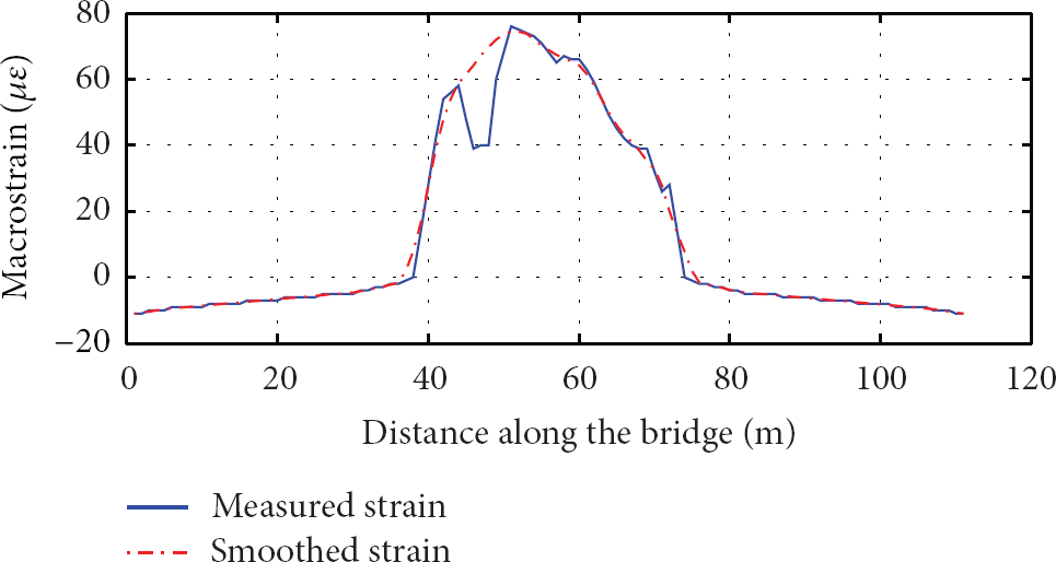
Strain distribution along the bridge for load case 1.
Based on the strain distribution and (1) and (2), the deformation distribution can be calculated as shown in Figure 15. It shows that the maximum deflection happens also at the middle of the main span and is approximately 28 mm. However, it should be noted that if the deflection is calculated directly using the measured strain without ruling out bad measurement value, then the maximum deflection value will be about 1.5 mm smaller than that calculated by the smoothed strain distribution

Deflection distribution for load case 1.
For load case 2, trucks were stopped at the quarter-span of the main span as shown in Figure 16. Figure 17 shows the corresponding strain distribution and Figure 18 shows the deformation distribution calculated based on strain distribution. The maximum strain is 38

Load case 2.

Strain distribution along the bridge for load case 2.

Deflection distribution for load case 2.
Figure 19 shows the load case 3 while Figures 20 and 21 demonstrate the corresponding strain distribution and deformation distribution, respectively. The minimum strain is about −18

Load case 3.

Strain distribution along the bridge for load case 3.

Deflection distribution along the bridge for load case 3.
4.3. Braking Testing
In order to study the impact resistance and dynamic characteristics of the bridge, vehicle brake testing was conducted. A 30-ton truck with the speed of 20 km/h suddenly braked at the midspan, and the response of the sensor which was at the midspan shows that the maximum strain is 7.7
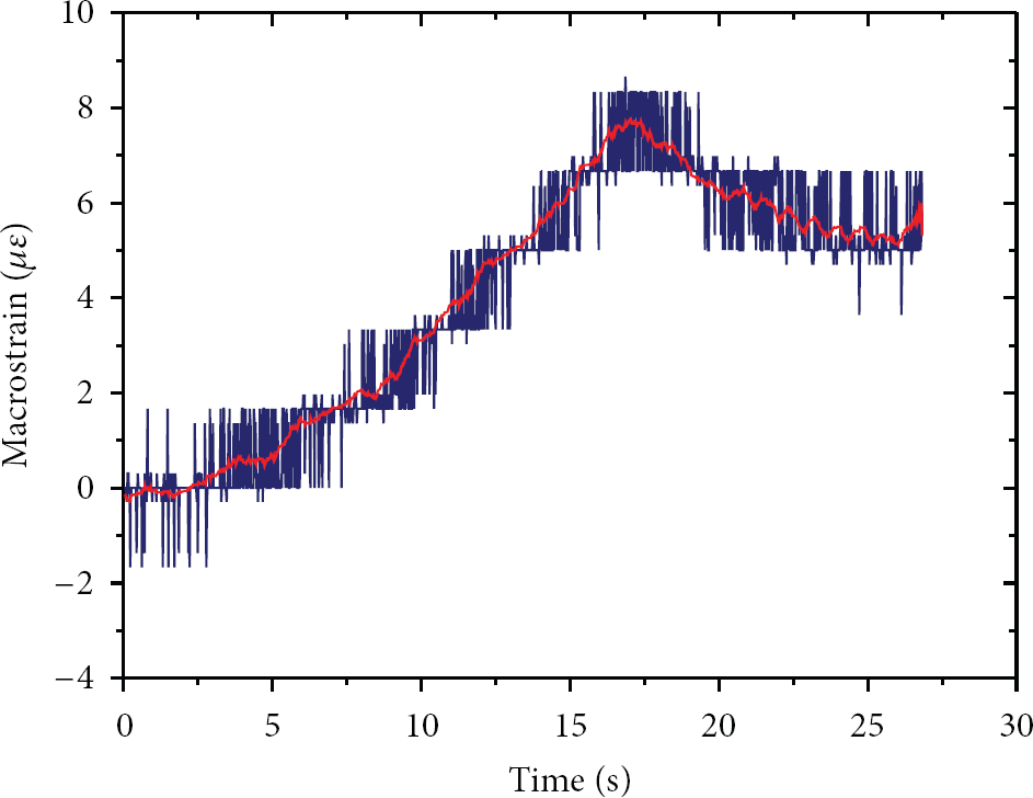
Macrostrain time history during brake testing.
4.4. Health Monitoring Using Dynamic Testing
Structural health monitoring of the Hongxing Bridge using distributed long-gage FBG sensor has also been performed via the dynamic testing. Dozens of macrostrain time serial samples with each lasting for about several minutes were collected under ambient vibration. The sampling frequency was adopted to be 500 Hz. The signals were analyzed in frequencydomain and their power spectral densities (PSDs) extracted from 3 randomly selected macrostrain signals and 3 acceleration signals from accelerometers are shown in Figures 23(a) and 23(b), respectively. It is evident that the first order natural frequency from FBG strain response is in accordance with the one from the accelerations, that is, about 2.37 Hz for all cases.
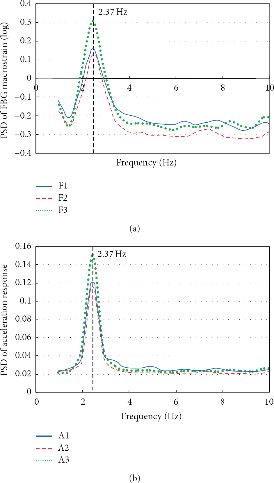
Power spectral densities for Macrostrain and acceleration responses.
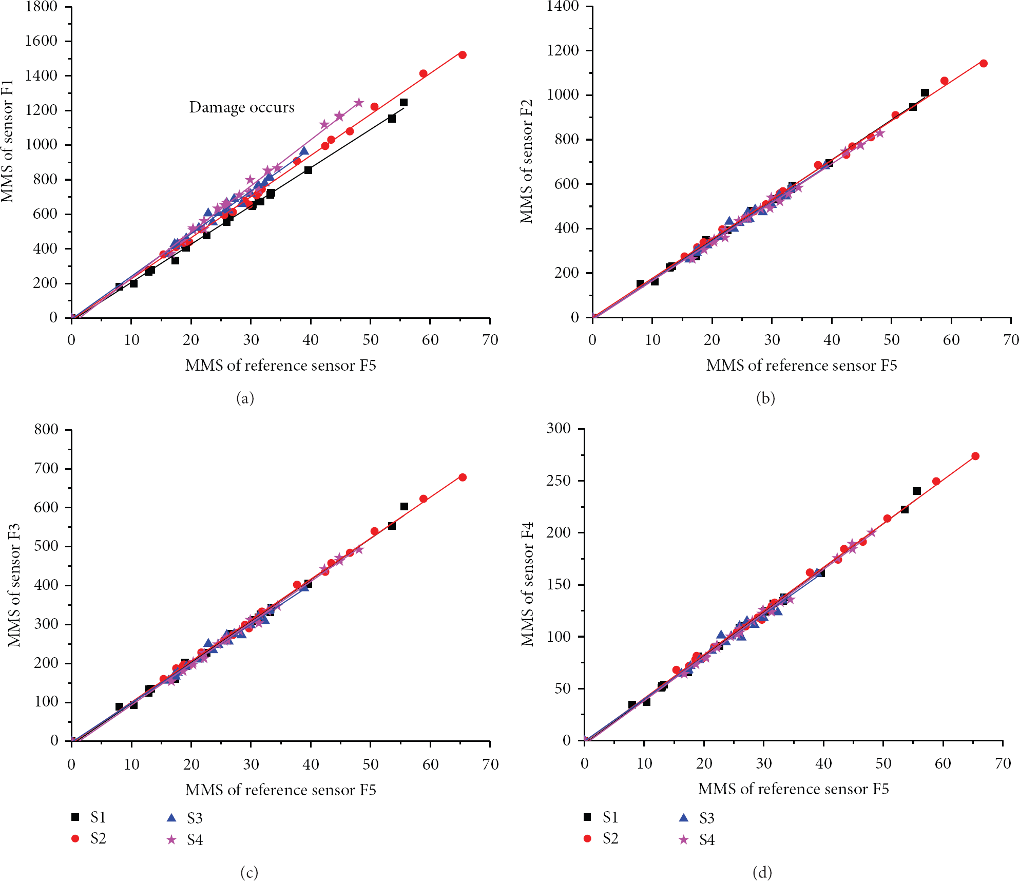
Figure 24 shows the statistical features of the MMS of the target sensor with respect to the reference sensors. Several tests were conducted within the period from June, 2010, to November, 2012. The MMS of other FBG strain response have the analogous results. After testing several times, the ratios of MMS at the target sensor to that of the reference sensor should be stable around at a constant value if no damage occurs within gauge length of the target sensor. In this case, the slope of fitting line from a group of data should keep constant, even though the ratio for every single sample may differ slightly from each other due to noise pollution. However, when damage occurs within the gauge length of the target sensor, the MMS of the structure will change and hence the ratio to the reference MMS will also change. Thus the fitting line will deviate from the one in undamaged case. Figure 24 shows two randomly selected samples of the testing. Results show that fitting line does not have much deviation and therefore indicates the healthy status of the corresponding part of the structure.

MMS of the long-gauge sensors with respect to a reference sensor.
5. Conclusions
In this paper, bridge assessment and structural health monitoring with distributed long-gage FBG sensors are introduced. Its application to the laboratory experiments and real bridge is also addressed. It shows the developed long-gauge FBG sensors can provide a satisfactory measurement and monitoring for actual large-scale infrastructures. With distributed long-gage FBG sensing technique, the global information of the bridge such as deflection and natural frequency can be obtained effectively. At the same time, the local information, strain distribution, can be also acquired. Using the normalized MMS together with the statistics analysis, structural damage identification can be realized, which may be a very useful method for civil engineering structures.
Footnotes
Acknowledgments
This work is supported by the National Key Technology Research and Development Program of the Ministry of Science and Technology of China (Grant no. 2011BAK02B03), the Jiangsu NSF (no. BK2010015), the Project Funded by the Priority Academic Program Development of Jiangsu Higher Education Institutions (PAPD), major project of Department of Communications of Jiangsu Province (2011Y03), and Graduate Research and Innovation Plan Project for the Regular Institution of Higher Learning in Jiangsu Province & Fundamental Research Funds for the Central Universities (no. CXZZ12_1208).