
Abstract
In recent years, some approaches have been presented for the seamless integration of WSNs with the existing, widely deployed SOA technologies such as XML, Web services, and the Business Process Execution Language (BPEL) to build a wireless sensor networks service application. However, there a great challenge on fault tolerant in WSNs. In this paper, we present our framework and approach to enhance the reliability of service composition applications in WSNs through modeling and analyzing a wireless sensor networks service application based on BPEL with exception handler and compensation mechanism. At first, we analyze all possible states during the execution of BPEL instance in WSNs. Then, we present a state framework for modeling execution context in BPEL instance in WSNs. Based on this framework, we analyze state transition and operational semantics in the case of both correct execution and exceptional execution of BPEL instance in WSNs. Furthermore, we propose the state transition models for three types of activities in BPEL instance. In the end, we present a formal approach to model the execution context in BPEL for WSNs. Using this formal model, one can describe and analyze the control flow result from the exception handler and compensation mechanism in BPEL instance for WSNs.
1. Introduction
Despite the amount of research targeted at middleware systems for wireless sensor networks (WSNs), they are still not widely used in industry. Certainly, one major issue is the different programming methodology. While WSNs are optimized for low-power, low-cost, and a small form factor, Enterprise-IT systems are typically equipped with more resource and are connected to the power grid. In Enterprise IT, it is significant to adapt business processes and the underlying software infrastructure quickly and flexibly to react to changes on the markets. To achieve this goal, organizations focus on modeling, analysis, and adaptation of business processes since the early 1990s. With the advent of service-oriented architecture (SOA) based on Internet standards, more and more businesses are transferred to this architecture.
Parallel to this development, WSNs are envisioned to become an integral part of the Future Internet where they extend the Internet to the physical world. Combined with each other, these two trends lay the groundwork for a new class of applications where all kinds of devices ranging from simple sensor nodes to large-scale application servers interact to drive business processes which were not possible before. That way, data stemming from a WSN may influence the control flow of a business process in real time or even trigger a business process. To achieve this level of integration, WSNs must seamlessly interoperate with the existing widely deployed SOA technologies such as XML, web Services, and the Business Process Execution Language (BPEL) to name only a few. In recent years, some approaches have been presented for the seamless integration WSNs with these SOA technologies to build a wireless sensor networks service application successfully. In these approaches, WSNs are packaged as some standard Web services which can be published, located, and invoked across the Web. Therefore, based on BPEL, these WSNs services can be combined into a workflow to fulfill some certain tasks in a web services composition (WSC) way.
As standard Web services, the capsulated WSNs are of all characters of Web services. Web services provide the basis for the development and execution of business processes that are distributed over the Internet and are available via standard interfaces and protocols [1–3]. Web services have the characters of interoperation, platform independent, self-described, and loose coupling [4]. Web service composition (WSC) is one of the most promising ideas underlying Web services: new functionalities can be defined and implemented by combing and interacting with the preexisting Web services. WSC refers to the process of composing multiple stateless atomic Web services into statefull complex applications [5–8].
Under satisfying the precondition of functional demands, the fault tolerant is the key for a wireless sensor networks service application. However, deploying a test-bed system to evaluate WSNs application system is very expensive and time consuming. Therefore, the performance modeling and analysis of WSC in WSNs is the important research direction of business process reengineering [9–17].
In our previous work [18, 19], we studied the performance modeling and analysis methods for the basic control flow of WSC under the circumstance that BPEL instance is executed correctly. We presented a novel performance simulation model for WSC, called STPM+. The STPM+ model can support modeling and simulating the time and nontime QoS metrics of WSC. Based on the stochastic timed colored Petri net, the STPM+ model can simulate and predict multiple QoS metrics such as cost, reliability, and credibility. We designed and realized a visual performance simulation tool, called VisualWSCPE. One can simulate and analyze the execution of BPEL instance, assess its performance, and find out the potential performance bottlenecks with VisualWSCPE. However the transaction property of WSC in WSNs is not considered during we fulfilled the above modeling and analysis. This means that the execution context in BPEL cannot be modeled and analyzed based on the above model. So, the modeling and analysis for the transaction and exception handling of BPEL instance in WSNs should be studied further.
Transaction is a very important concept related to exception handling and compensation [18, 19]. Transaction constitutes a single set of the logical operation unit. All operations should be completed successfully, or fail totally and roll back to the previous state before the transaction is executed [20, 21]. In order to ensure its integrity, transaction should have four properties: atomicity, consistency, isolation, and durability, which are called ACID [22, 23].
Business processes often need to use the concept of transaction to handle exception and compensation. The use of ACID transactions is usually limited to local updates because of trust issues in a business process. Because the invocation of Web service cannot usually lock the resources across different enterprises, the common transaction mechanism, for example, two-phase commit, cannot be used to handle this circumstance. Besides, the locks and isolation cannot be maintained for a long period during occurrence of the technical and business errors. Consequently, the demand of long-running transactions (LRT) is put forward [20]. LRT refers to a longer duration transaction, which cannot achieve the restoration of data and state through the common rollback mechanism. Because the cross-organizational resources cannot be locked, even if the invoked atomic Web services under LRT all meet the requirements of ACID, the overall LRT cannot still satisfy the requirements of ACID [24, 25]. Generally, when an LRT fails, the simply rollback will be used to undo the effects resulted from these executed operations. A reverse process is used to perform these rollback operations, which is called “compensation” [26, 27]. Compensation is a particular approach to the business data management. So, it is always a part of business logics. The roll of compensation in LRT is different from that of atomic rollback operations provided by database management system for ACID of transaction. The roll of compensation in LRT is reflected in the improved security. For example, in the Internet, one may lock a company's data by performing an invocation operation to a certain Web service. The invocation operation in LRT might result in the denial of service attacks in the case of traditional transaction handling. Compensation in LRT can avoid this problem. The use of compensation means that data will not be locked in a long duration. So, the business data cannot be locked in a long period time and the denial of service will never happen. However, the use of compensation also causes a new problem simultaneously. It results in the fact that the LRT loses ACID prosperities and the isolation cannot be at least satisfied. It is because the business data is visible in the whole transition duration from the initial update operation to compensation.
BPEL provides some compensation mechanisms by providing the ability for flexible control of the reverse operation. In BPEL, the fault handling and compensation can be defined to support LRT in an application-specific manner [28, 29]. Compensation operations are triggered by the occurrence of exception event in BPEL specification [30].
To verify the availability of exception handling and compensation mechanism of BPEL instance in WSNs, we validate the modeling and analysis methods for the execution context of BPEL in this paper. Our contributions are threefold.
We present a state framework of WSC for WSNs that is based on BPEL. Based on this framework, we can analyze and construct state transition model for all kinds of BPEL activities in WSNs. For three kinds of activities in BPEL: basic activity, structural activity, and scope activity, we analyze various state transitions in terms of respective mechanisms of exception handling and compensation in WSNs. And we present the state transition models for each activity in BPEL. Based on our state transition models, one can build the state transition system of WSC for WSNs. We present an approach to model the state transition process with state transition system for WSNs. Using the approach mentioned above, one can describe and verify the control flows resulted from exception handler and compensation mechanism of BPEL instance for WSNs.
This paper is organized as follows. The next section introduces the related works on modeling and analysis of execution context in BPEL instance for WSNs. In Section 3, we analyze all possible states in BPEL instance for WSNs at first. Then we present a state framework for the execution context in BPEL by which we can analyze exception states and compensation states of BPEL activities. In Section 4, we analyze the state transitions of three types of activities of BPEL based on the state framework for WSNs at first. Then we present their state transition models, respectively. In the end, we present a formal approach to model the execution context of BPEL for WSNs based on the state transition model in Section 5.
2. Related Works
This paper focuses on the modeling and analysis of the execution context of BPEL. There have been several formal models presented in the literature. Kazhamiakin et al. [31] made researches on the communication behaviors of different participants in BPEL and presented an approach to model such behaviors. It describes the different states in course of execution of BPEL activity and the process by which the system evolves to a new state resulting from executing some actions. In addition, Kovács et al. [23] proposed a formalism method for capturing the behaviors of business process implemented in BPEL.
It uses transition system as the formal model of workflow and presents the state transition models of different activities. Furthermore, Nakajima [32] presented a model based on the extended finite automation to analyze the instance of BPEL, which maps every control flow into individual extended finite automation, so every activity can be modeled into different extended finite automation.
However, there are some limitations in the above researches. Because the above studies mainly concentrate on the verification of the static model of the instance of BPEL, the temporal behaviors are not considered during the execution of BPEL instance. Besides, the state transition model presented in [18] only describes the communication behavior of business process. The restriction condition of state transition is not considered. So, it is not sufficiently complex to model and simulate the dynamic execution of the instance of BPEL. In addition, the state transition system proposed in [31] presents the state transition model of basic activity and structural activity, but these models are too simple to cover all states in the course of execution of structural activity. And these models do not consider the restriction condition of state transition. So, they are unable to describe the behaviors and states during the execution of the instance of BPEL. In the end, the model proposed in [23] does not consider event, fault handling and compensation, so it cannot obtain all states and behaviors during the execution of the instance of BPEL.
To overcome the above shortcomings, we analyze all possible states in the execution of the instance of BPEL at first. Then, we present a sufficient state frame model to capture the communication behavior and all states of BPEL instance. Based on our state frame model, we construct a state transition system for modeling the execution context of BPEL instance. And we analyze the operational semantics of state transitions.
3. State Analysis of the Activities in BPEL
Web services that are modeled by WSDL are stateless. It means that the states of Web services cannot be captured and maintained. BPEL can describe the invocation relationships among Web services components within a business process. So, it can be used for modeling a WSC instance. Moreover, BPEL provides the context of behaviors of each activity including fault handlers, event handlers, compensation handlers, data variables, and correlation sets. When an activity instance is finished, the next activity instance to be executed is selected and its state is changed to Ready. After this, the instance of activity may go through a number of internal states. Finally, if all the associated processing has been performed successfully, its state is changed to Completed. These two states are crucial to control flow. And any formal semantics of control flow constructs has to take at least these two states into account explicitly.
In BPEL, the LRT mechanism is supported by an essential concept scope. We can regard scope as a kind of special activity which can include other activities. All the activities in a scope have three running modes.
Mode 1. When a <scope> activity starts running, it will execute in a normal way. So, all the activities and event handlings within the <scope> will be executed normally.
Mode 2. During the execution of <scope> activity, once a certain activity instance has a fault, the running mode of <scope> activity will change from normal to fault handling. In consequence, all the activities and event handlings will receive the termination message to be stopped.
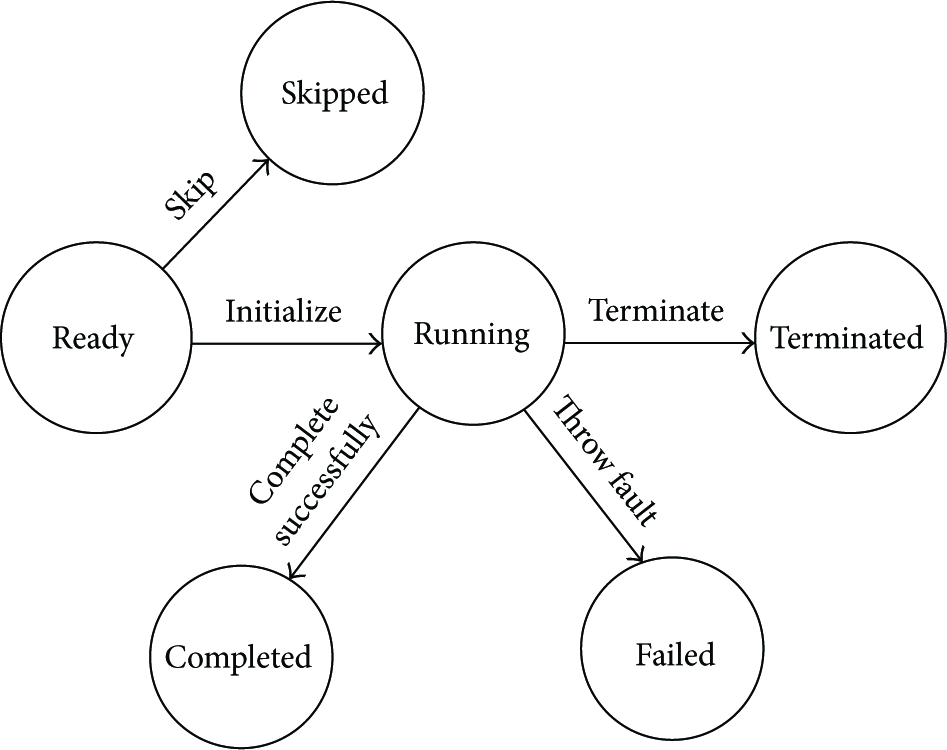
Mode 3. After all the activities and event handlings are stopped successfully, the <scope> activity will execute compensation handling. In this case, the compensation handling will remove the effects of fulfilled activities within the <scope> activity and restore them to the former state. Figure 1 shows the compensation mechanism.

The compensation mechanism in long-running transition.
Besides the <scope> activity, BPEL also provides a structure, called control link, and two kinds of labels related to activity, called join condition and transition condition, which are used for the definition of priority level, synchronization, and conditional dependency. BPEL provides a mechanism, called dead path elimination, to prevent the emergence of death lock. Suppose that there is a control link between activity A and activity B. Then, it indicates that B cannot start running before A has fulfilled or has skipped. B can start running only when the join condition is true. Otherwise, B would be skipped. Thus, activity should have a skipped state to support the dead path elimination mechanism.
A composite Web services must go through several internal states from ready state to completed state. It is obvious that the running state hides in the internal states of composite web service. Due to the conditional dependency, the composite Web services must wait for the end of execution of other services and then it can be instanced and executed. Thus, the parent service of the composite Web services is blocked which indicates that the state of the parent service is a blocked state.
Based on the above analysis, we consider that a composite Web services owns seven states as follows.
Skipped. BPEL provides a construct known as control links which, together with the associated notions of join condition and transition condition, supports the definition of precedence, synchronization, and conditional dependencies. A control link between activities A and B indicates that B cannot start before A has either completed or has been “skipped.” Moreover, B can only be executed if its associated join condition evaluates to true; otherwise, B is skipped. Ready. Composite Web service is initializing. Running. Composite Web service has finished initialization and is running. Blocked. Due to synchronization, a composite Web service needs to wait for the completion of other composite Web services. Failed. Composite Web service has the fault during its running. Terminated. Composite Web service completes unsuccessfully or is terminated by context. Completed. Composite Web service performs successfully.
Figure 2 shows our state framework for a composite web service. Based on this state framework, we can build state transition model for all kinds of BPEL activities.
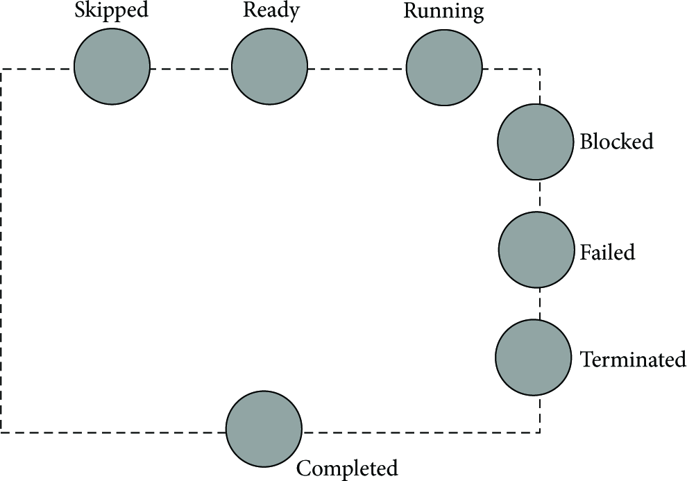
The state framework.
4. State Transition Model of Activities in BPEL
There are three kinds of activities in BPEL: basic activity, structural activity, and scope activity. We analyze the state transitions in terms of their respective mechanisms of exception handling and compensation handling.
4.1. State Transition Model of Basic Activity
Given that the initial state of a basic activity x is Ready, which indicates that its initialization has not completed. If x has a synchronization dependency on y and its join condition is false through evaluating this condition, and suppress join failure prosperity of BPEL instance is set to true, x will be skipped and will not be performed. Therefore, its state will be changed to Skipped from Ready, or x will complete initialization and its state will be also changed from Ready to Running. Because the main role of basic activity is the data processing and communications between other activities, Failed state of the basic activity is related to itself, for example, the failure of network communication or database operation. If the fault has occurred, basic activity x will capture and throw this exception, and its state will be also changed from Running to Failed. Moreover, these exceptions always register their immediate scope activity as fault event, the corresponding scope activity will execute the fault handler, and it can forward termination event to the executing inner activities. Therefore, its state will be also changed from Running to Terminated. If x has completed successfully, its state will be also changed from Running to Completed. In consequence, Figure 3 describes the state transition model of common basic activity.
The state transition model of common basic.
However, there are several special basic activities, for example, <empty> activity, <wait> activity, <throw> activity, and <exit> activity. Their state transition models are different from others. <empty> activity cannot be terminated or skipped. It cannot also own failed state because it does not perform any operators. Therefore, <empty> activity owns Ready, Running, and Completed as shown in Figure 4(a).

The state transition models of special basic activities.
According to BPEL specification, <wait> activity cannot be skipped, because it does not own Failed state as shown in Figure 4(b).
The <throw> activity will explicitly throw exceptional event to its immediate <scope> activity. Generally speaking, this type of activity does not have a Completed state. And after throwing fault, it directly sets its state as Failed.
Similarly, according to BPEL specification, <throw> activity cannot be skipped and terminated. Therefore, it does not own Skipped and Terminated states. Its state transition model is described in Figure 4(c).
The <exit> activity will cancel the whole process instance. Its execution will trigger a termination event to Process. So when it has completed, its state will be changed to Terminated. Its state transition model is described in Figure 4(d).
The state transition of basic activity is triggered by the message events sent to its execution context, such as termination event or fault event. In general, the execution context of basic activity will receive the messages from its ancestor activities. Consequently, these messages will trigger the change of its state.
4.2. State Transition Model of Structural Activity
There are several structural activities in BPEL such as <flow> activity, <sequence> activity, <if> activity, <while> activity, <repeatuntil> activity, serial <foreach> activity, and <foreach> activity.
In this subsection, we mainly analyze the state transitions of these structural activities.
The <flow> activity provides concurrency and synchronization. Given a <flow> activity x, its initial state is Ready, which indicates that it has not finished initialization. If any branch of x has finished initialization; that is, the state of an inner activity within x is Running, the state of x is also changed from Ready to Running. If the state of x is Running, only when the states of all inner activities are changed to Completed, the state of x is changed from Running to Completed. If any inner activity of x throws the exception; that is, its state is Failed, the state of x is also changed to Failed, and x will send termination event for other inner activities, and if x receives termination event, it will also forward this event for its inner activities, only when all inner activities of x are Terminated successfully, and the state of x is changed to Terminated. If the state of x is Ready before finishing the initialization, and x has the synchronization dependencies on other activities, and its <joinCondition> is evaluated to false, its state is changed from Ready to Skipped. If the state of x is Running, and when the state of its all inner activities is Blocked, the state of x will also be changed to Blocked from Running as shown in Figure 5.

The state transition model of <flow> activity.
The <sequence> activity contains one or more activities that are performed sequentially. Given a <sequence> activity x, its initial state is Ready, and if the first inner activity has finished initialization and its state is Running, the state of x is changed from Ready to Running. Only if the last inner activity has completed successfully; that is, its state is Completed, the state of x is changed from Running to Completed. If an inner activity in activity x throws fault, the state of x is also changed to Failed. If x receives termination event, it will also forward this event for its inner activities, when only one inner activity of x is terminated successfully, and the state of x is changed to Terminated. In the course of the execution of x, if an inner activity z in activity x has the synchronization dependence on activity y (y is not the inner activity of x), z needs to wait for the successful completion of y. Therefore, activity x can be blocked because of the execution of y. In consequence, the state of x is changed from Running to Blocked. The transition process of its Skipped state is similar to <flow> activity. So the sate transition model of <sequence> activity is the same as <flow> activity, but the operational semantics of its state transition is only different from <flow> activity.
The <if> activity provides conditional behavior. The activity consist of an ordered list of one or more conditional branches defined by the <if> and optional <else if> elements. So the sate transition model of <if> activity is the same as <sequence> activity, but only the operational semantics of its state transition is different from <sequence> activity. When it selects one branch to execute, its state is changed from Ready to Running, and the state of the inner activities in other branches will be set to Skipped. Only when the state of the inner activity in any one branch is Blocked, its state will also be changed to Blocked.
The <while> activity, <repeatuntil> activity, and serial <foreach> activity provide iterative behavior. In BPEL specification, they cannot have the synchronization dependencies on other activities, so there is no the transition from Ready to Skipped in their state transition models.
And when their state transition semantic from Running to Completed is different from <sequence> activity, such transition must be satisfied with the completion condition and the successful completion of only one inner activity.
Parallel <foreach> activity will dynamically create and execute N+1 instances of the <foreach>'s enclosed <scope> activity as children in parallel until completion condition is satisfied. When completion condition is satisfied, if there are still the executing instances in the context, these instances will be forced to terminate. Because parallel <foreach> activity executes in parallel, its state transition model is the same as <flow> activity, but only its state transition semantic from Running to Completed is different from <if> activity, its transition must be satisfied with the completion condition or all instances' successful completion.
4.3. State Transition Model of Scope Activity
The <scope> activity provides the context of execution for its inner activities. Its difference from other structural activities is its special state transition model. The initial state of <scope> activity is Ready. When the main activity of <scope> activity has finished initialization and its event handler is also activated, its state is changed to Running from Ready. If in the course of execution the inner activities throw the exception, the fault handler will be triggered, and the state of <scope> activity will be changed to fault handling. In the course of such process, compensation handler is prohibited. When the fault handler has completed, its state is changed from fault handling to Failed. If <scope> activity has completed successfully, it means that this <scope> activity may be allowed to execute the compensation handler, once the compensation handler is triggered, its state is changed to under compensation from Completed. Until the compensation handler has completed, its state is also changed to compensated. Figure 6 shows the sate transition model of <scope> activity.

The state transition model of <scope> activity.
5. Modeling the Context of BPEL with State Transition System
In the above section, we discuss the temporal behavior of state transition and the transition conditions in BPEL activity. In general, the discussed state transition models correspond to state transition system, and such system may describe the dynamic process of the execution of BPEL, and the emerging states in the context can be evolved into new states after executing an action. The state transition of whole system is related to the following factors. The first factor is action. Action decides the state change of system, and the state transitions vary from the actions. Generally speaking, the system is related to input action and output action. Secondly, restriction also plays an important role in the state transition. If and only if the restriction conditions are satisfied, action can trigger the state transition of system, for example, in term with <flow> activity, the restriction of its successful completion is that its all inbuilt activities have completed successfully. Finally, the current state of system decides on the direction of state transition. Therefore, in this section, we present a state transition system which is used for modeling the context of BPEL activity.
Definition 1.
The execution context of BPEL activity is a state transition system, which is defined as in the following seven tuples:
𝒮 represents the finite state set of activity. If the type of activity is basic activity, then ℛ is a finite restriction set of state transition, δ is a function of state transition: θ is a mapping function:

According to the above definition, the state transition semantic discussed in Section 4 may be formally described. And this section also presents the approaches to construct such state transition system.
5.1. Constructing the State Transition System of Basic Activity
Figure 3 represents the state transition model of the most basic activities. Their state transition results from fault event, compensation event, termination event, message event, and alarm event in BPEL activity. Therefore, it is necessary to define the message and action related to these events.
Action may be classified to two types: input action and output action, which correspond to send and receive operations. In terms of state transition system discussed in this paper, we need to do a research on the relations of state transition in the same activity or different activities. In general, input and output action will send the notifications or command of state transition, so action in Definition 1 may be defined as follows:
ℳ is a message or event, 𝒪 is a composite Web service, namely, activity. 𝒪 is the source object of the sent message for input action, while it is the target object of the sent message for output action.

According to the above definition, we are able to formally describe the construction process of state transition system of basic activity. Let
Ready → Running
where
parents(x) is a set of immediate ancestor of x. Running → Completed
Running → Terminated
<exit > activity
Other basic activities
Running → Failed
<throw > activity
where parentscope(x) represents its immediate father <scope > activity. Other basic activities

5.2. Constructing the State Transition System of Structural Activity
Section 4.2 represents the state transition model of structural activities. The state transition of structural activities results from the state of their inner activities, input action and output action. The state of inner activities restricts the state transition of structural activity and partly decides the input action of structural activity. In consequence, we will discuss the restriction condition of state transition of structural activity, and input actions result in state transition and output actions. Because <scope> activity is special structural activity, so we will discuss how to construct its state transition system in the next subsection.
Ready → Running (
where
Running → Completed
<sequence > activity
<flow > activity (
Iterative activity (
<if > activity (
Running → Terminated
<flow > activity (
where <sequence > activity and <if> activity (
Iterative activity (
Running → Failed
Running → Blocked
<sequence > activity (
Other structural activities (
Blocked→Running
<sequence > activity (
Other structural activities (
5.3. Constructing the State Transition System of Scope Activity
Section 4.3 presents the state transition model of <scope> activity. The <scope> activity is equivalent to the scope of program language. It provides long-running transaction for process fragment in its scope. Because <scope> activity is also belonging to structural activity, its state depends on the states of its inner activities. According to Figure 6, the state transition system of <scope> activity is generated by the following approach.
Ready → Running (
where
Running → Faulthandling (
Faulthandling → Failed (
Running → Completed (
Completed → Under compensation (
where
childrenscope(x) are <scope > activities immediately enclosed by x. Under compensation → Compensated (
6. Conclusion and Future Work
In order to enhance the reliability of service composition applications in WSNs, we study the modeling approach of the execution context in the instance of BPEL for verifying the availability and operational semantics of exception handling and compensation mechanisms in BPEL instance for WSNs in this paper. At first, we discuss the possible states of a BPEL activity during the execution of the instance of BPEL. Secondly, we propose the respective state transition models for three types of BPEL activities and analyze the operational semantics for the state transitions. Finally, we present an approach to model state transition process by state transition system in order to describe and analyze the control flow resulted from exception handler and compensation mechanism for WSNs.
In the future, we plan to study how to evaluate the availability, operational semantics, and the efficiency of exception handling and compensation in BPEL instance for WSNs based on a rule system. So, a set of rules based on operational semantics for finding out the problems in exception handling and compensation are the key content in our future work. Simultaneously, we also plan to transform a state transition system of the instance of BPEL to a Petri net model. Thus, we can use Petri net theory and method to analyze and evaluate the availability, operational semantics, and efficiency of the state transition system easily.
Footnotes
Acknowledgments
This work was supported by the National Natural Science Funds Fund of China (61172084), the National High-tech R&D Program of China (2007AA01Z138), Natural Science Foundation of Hubei Province of China (2010CDB5201), Education Commission of Hubei Province, China (Q200625001), Xiangfan Municipal Science and Technique Foundation (2008GG1C41).