
Abstract
The debris detection system is simulated and analyzed with the software of Maxwell 14 in this paper. The magnetic induction intensity and the magnetic density of the detection system with metal debris are simulated. The static experimental system is designed to measure the inductance caused by different metal debris. The simulation and experimental result indicate that the nonferromagnetic metal debris reduces the inductance of microplane inductance sensor and that ferromagnetic metal debris increases the inductance of microplane sensor. The detection of metal debris with microplane sensor is feasibly proved by the research. This paper provides a model for detecting the debris with a plane eddy current sensor and a case for the 3D simulation of the eddy current. This work may have some significance for improving the efficiency of the plane eddy current sensor.
1. Introduction
Metal debris will be produced by the friction of the mechanical equipment during the running and manufacturing. It will suspend in oil of the equipment system and then do harm to the equipment. Therefore, the detection of the debris is important for predicting the failure of the wear, reducing major accidents and economic losses [1]. There are many methods that can be selected to detect the debris in the oil. The detection with microinductance has been studied by many scholars because of the high sensitivity, easy integration, and modularization. It has been applied to the measurement of displacement, speed and nondestructive testing [2]. Feng et al. [3] researched the inductance, and quality factor of the plane inductor, and concluded that the inductor had a good inductance and quality factor while the frequency was 1 MHz. Wang et al. [4] studied the plane inductance with the software of Maxwell. Gao et al. [5] and Sadler et al. [6] calculated the inductance of the microplane inductance. Fan et al. [7] researched the metal debris detection with solenoid inductance sensor. Du et al. designed an experiment for detecting the debris in a microchannel with a microplane sensor, which could distinguish the different sizes of the debris by the change of the sensor inductance [8, 9]. He also studied the double microplane inductance sensor [10]. However, most of these researches did not deal with the quantitative influence of the magnetic field and the change of the inductance in calculation affected by the metal debris. The model of debris detecting system is built with the software of Maxwell 14 in this paper in order to simulate the changes of inductance and the changes of magnetic field of the coil. Experimental detection of metal debris is also carried on. The results of simulation and experimental are compared.
2. Detection Principle and the Design of Detection System
2.1. Detection Principle
The principle is that different metal debris has different influence on the inductance of the microcoil. The ferromagnetic debris and nonferromagnetic metal debris can be distinguished according to the influence on the inductance of the microcoil. The size of debris can also be recognized according to the quantity of changes on the inductance. The inductance of microcoil can be calculated with formula (1):
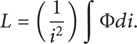
Here Φ is the magnetic flux and i is the current element.
The magnetic flux Φ can be calculated by formula (2)
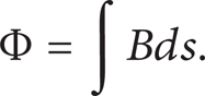
Here B is the magnetic induction, s is the area element.
There will be an alternating magnetic field around microcoil while the alternating current passes the microinduction coil. The relation between the magnetic field and the current is shown in Figure 1(a). The magnetic field will be affected while nonferromagnetic metal debris is near to the microcoil as shown in Figure 1(b). The eddy current will be generated in the metal debris because of the alternating magnetic field [11]. The direction of the magnetic field that generated by eddy current is opposite to the magnetic field that generated by the microcoil. So the result is that the magnetic field of the microcoil decreases. It can be indicated that the inductance of microcoil will decrease while the magnetic field reduces with formulas (1) and (2). Therefore, the inductance will decrease while the nonferromagnetic metal debris nears the sensor. The magnetic field of the microcoil with ferromagnetic metal debris is shown in Figure 1(c). The ferromagnetic metal has large permeability. So the magnetic induction will increase due to the magnetization effect. The magnetization effect is greater than eddy current effect. The inductance of microcoil will increase because of the large permeability [12]. Therefore, the material of the metal debris can be recognized according to the increase or decrease of inductance. The debris's size can be identified with the quantity of inductance change.
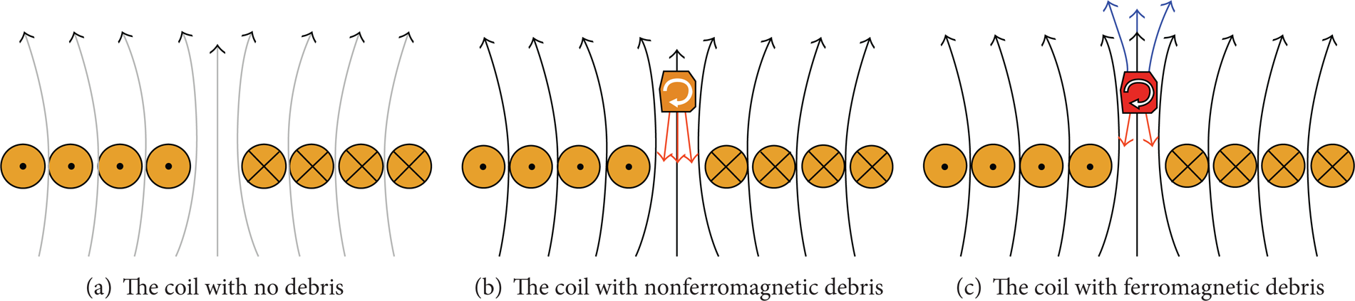
The schematic drawing of the microinductance sensor. The black arrow lines indicate the magnetic lines generated by the coil, the orange arrow lines indicate the magnetic lines of force generated by eddy current, the blue arrow lines indicate the increasing magnetic lines by the ferromagnetic debris, and the white arrow lines indicate the direction of the eddy current, the irregular geometry indicates the metal debris, and the circular arrangement indicates the coil.
2.2. Static Detection System Design
The static detection system designed for detecting the metal debris is shown in Figure 2. The system is consisting of probe, metal debris, sensor, impedance analyzer, computer, and 3 axes platform. The metal debris is fixed on the tip of the nonmetal probe. Then the probe is installed on the 3 axes platform. The location of the metal debris relative to the microcoil can be controlled by adjusting the 3 axes platform.

The schematic drawing of static detection system. 1 is the 3 axes platform, 2 is the probe, 3 is the metal debris, 4 is the sensor, 5 is the lug boss, 6 is the impedance analyzer, and 7 is the computer.
The microinductance coil with 14 turns is fabricated with PCB fabricate process. The width of coil line is 100 μm, and the space between lines is 100 μm also. The photograph of the coil is shown in Figure 3.

The photograph of microinductance coil.
The metal debris is fixed on the tip of the nonmetal probe. Then the probe is installed on the 3 axes platform. The location of the metal debris relative to the microcoil can be controlled by adjusting the 3 axes platform.
The metal debris is adjusted on the top of the microcoil, and the distance between the debris and the coil is 200 μm while detecting the inductance of the microcoil. The inductance of coil will be detected while the distance increases by adjusting the 3 axes platform. The detection current frequency is 1 MHz while measuring the inductance of the microcoil.
3. Finite Element Simulation
3.1. Calculation Theory of Eddy Current Field
Alternating magnetic field will appear while alternating current passing through the microcoil. Then the alternating magnetic field will generate an eddy current in the metal debris. The calculation of the eddy current field is to solve the Maxwell equations in the given boundary conditions. The differential form of the Maxwell equations can be expressed as (3) for general time-varying field:

Here H is the magnetic field intensity, J is the current density vector, D is the electric field vector flux density, E is the electric field intensity, B is the magnetic induction, and ρ is the volume density of charge.
The homogeneous wave equations satisfied the needs of 3D-eddy current field are shown in (4):

Here ∊ is the dielectric constant of medium, μ is the differential permeability, σ is the conductivity of medium, and j is the unit of imaginary.
The magnetic field intensity H is described as (5) in the simulation of Maxwell 3D-eddy current field:

Here T is the potential electric vector, φ is the potential electric scalar, and H p is the magnetic field intensity at the edge.
The value of T is zero while the area is insulated. Only φ and H p should be calculated. T still should be calculated while the area is conductive.
The boundary conditions and solving precision are set after the model is built. Then the software starts to calculate, generate the initial split of the model and analyze the error. If the result satisfies the terminal conditions, it will be output the result, or else, the mesh will be refined and the field will be recalculated. The computational flow diagram is shown in Figure 4.

The computational flow diagram.
3.2. Model Establishment and Parameters Selection
The software of Maxwell is adopted to build and analyze the metal debris detection system. The simulation model is built with the software of Maxwell as shown in Figure 5. The coil is set on the PCB board. The thickness of the PCB board is 0.4 mm. The width of the coil line is 100 μm with 100 μm line space and the thickness is 35 μm. The debris is over the sensor. The debris is gathered in the oil and can be calculated as a metal ball [13]. So the shape of the debris is set as a ball whoes diameter is 150 μm. The coil is covered with medium and its size is 9000 μm × 9000 μm × 9350 μm (length × width × height). The whole boundary condition is set as radiation boundary.

The simulation model of the system.
The material of the coil is set as copper, the medium is set as air, and the metal debris is set as iron or copper. The magnetic permeability and the electrical conductivity of the material are set as isotropic. The specific parameters of material in the detection model are shown in Table 1.
Parameters of material adopted in the model.

3.3. Definition the Specification of Solution
The inspirator alternating voltage is 0.5 V and the resistance of the microcoil is 1.088 Ω in the experimental measure of the inductance of the microcoil. So, the peak value of current is set as 0.65 A and the solving frequency is set at 1 MHz. The auto adaptive analysis is selected and the number of the iterations is set as 20 times. The percentage of new mesh will be added after each adaptive loop is set as 30%. The shape of mesh is tetrahedron and the number of mesh is set as 50000. The model is solved and the mesh is refined according to the parameters. The mesh result of the microplane coil is shown in Figure 6 and the mesh result of metal debris is shown in Figure 7.

The mesh of the microplane coil.

The mesh of metal debris.
4. Comparison of Simulation and Experimental
4.1. The Influence on the Magnetic Field
The magnetic field of microcoil is simulated with the model being set up in the software of Maxwell. The debris of iron is set as 150 μm in diameter. The distance between the coil and the iron debris is 200 μm. The debris of copper is set as 150 μm in diameter. The distance between the coil and the copper debris is 50 μm. The magnetic field of microcoil without debris is shown in Figure 8. The magnetic field intensity of microcoil with iron debris is shown in Figure 9. The interior magnetic field of the iron debris is reduced according to Figure 9. The direction of magnetic field generated by the eddy current in the iron debris is opposite to the magnetic field of the microcoil. So, the total magnetic field is decreased in and near the iron debris. The magnetic induction of the microcoil is shown in Figure 10. However, the inner magnetic induction of the iron debris increases from 3 × 10⁻³ T to 7 × 10⁻³ T. Figure 11 is the enlarged drawing of the magnetic induction of the iron debris. The magnetic induction in the debris is not uniform because of the education current of the microcoil. The education current is not helix as the coil. The part of the debris far from the coil has a larger magnetic induction than the side near the coil. The magnetic induction field is also asymmetric due to the asymmetry structure of the coil.

The magnetic field with no debris.

The magnetic field with iron debris.
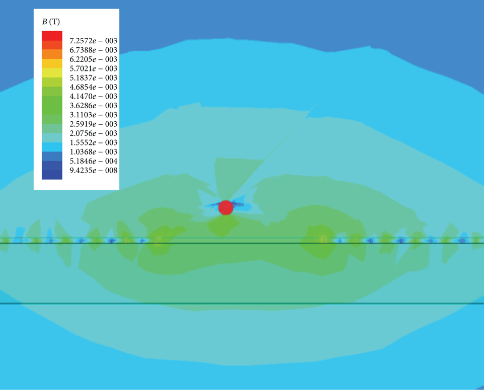
The magnetic inductance with iron debris.

The magnetic inductance of iron debris.
The magnetic inductance field of microcoil with copper debris is shown in Figure 12. The magnetic induction field around and in the debris becomes lower by comparing with no debris. The magnetic inductance near the copper debris decreases from 3 × 10⁻³ T to 3 × 10⁻⁴ T. This is because of the direction that occurred by the eddy current is opposite to the magnetic field of coil. The magnetic field of microcoil with copper debris is shown in Figure 13. The value of magnetic field (H) is similar to magnetic induction field (B) because the relative permeability of copper is approximate to 1.

The magnetic inductance field with copper debris.

The magnetic field with copper debris.
4.2. The Influence on the Inductance of the Metal Debris
The influence on the inductance of the microdetection coil is simulated with the software of Maxwell. The simulation result of the inductance is 736.783 nH while there is no debris near the coil. The experiment testing value is 705.48 nH while there is no debris near the coil. Copper and iron debris are fabricated for the experimental testing. The micrograph of copper debris is shown in Figure 14, and the micrograph of iron debris is shown in Figure 15. All the debris is about 150 μm in diameter. The experiment is carried on with debris and the static detection system.

The micrograph of copper debris.
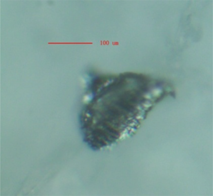
The micrograph of iron debris.
The simulation inductance and experimental inductance of microcoil with iron debris are shown in Figure 16. The inductance of the experiment is 706.48 nH and the simulation value is about 737.6615 nH, while the distance between the coil and debris is 200 μm. The inductance is simulated and measured while every 200 μm increased in distance between the microcoil and the debris. Both the simulation and experiment inductance decrease while the distance increases. The relation between the change rate of inductance (ΔL/L) and the distance is shown in Figure 17. The change rate of inductance also decreases while the distance increases. The change rate of inductance in simulation and experimental is consistent.

The change of inductance caused by iron debris.

The change rate of inductance caused by iron debris.
The simulation inductance and experimental inductance of microcoil with copper debris are shown in Figure 18. The inductance of the experiment is 705.08 nH and the simulation value is about 736.308 nH while the distance between the coil and copper debris is 200 μm. Both the simulation and experiment inductance decrease while the distance increases. The relation between the change rate of inductance value (ΔL/L) and the distance is shown in Figure 19. The change rate of inductance in simulation and experimental tests is consistent. The change rate of inductance caused by copper debris is smaller than that caused by iron debris when debris is at the same size.

The change of inductance caused by copper debris.

The change rate of inductance caused by copper debris.
5. Conclusion and Discussion
The coil of the microinductive sensor is made of copper and its size is very small. The education wire of the sensor and the copper in the sensor will affect the inductance during experimental detection of the metal debris. The excess wires will increase the inductance value of the sensor. Several methods are adopted in order to decrease the measuring errors. The inductance of sensor connected with wires and the inductance of wires are measured, respectively. Then inductance of sensor is obtained with the total inductance subtract the inductance of the wire.
The accurate size of the debris is difficult to be ensured in the production process. Therefore, the debris is observed and selected repeatedly with microscope to ensure that the size is near 150 μm in diameter. The test is carried on in the cleaning room in order to reduce the impact of environment.
The error also comes from the following conditions. The magnetic loss is not considered in the simulation. The material property in the simulation and the actually measuring material property are not entirely consistent. Besides, there is a class of errors coming from the division of the grid and the setting of the error rate in simulation. These may cause the difference between the simulation inductance and the experimental inductance of the microcoil in the detection of the metal debris.
The debris detection system is simulated and analyzed with the software of Maxwell 14 in this paper. The magnetic induction intensity and the magnetic density of the detection system are simulated. This simulation information indicated that the nonferromagnetic debris reduces the inductance of microplane inductance sensor and ferromagnetic debris increases the inductance of microplane sensor. The detection of metal debris with microplane sensor is feasibly proved by the simulation and the experimental test in this paper. This paper provides a model for detecting the debris with a plane eddy current sensor and a case for the 3D simulation of the eddy current. This work may have some significance for improving the efficiency of the plane eddy current sensor.
Conflict of Interests
The authors declare that they have no conflict of interests.
Footnotes
Acknowledgments
Project of the National Natural Science Foundation of China no. 51105011 supported this research. This work was supported by the Specialized Research Fund for the Doctoral Program of Higher Education (no. 20101103120002). Project of Beijing Board of education no. KM201210005015 supported this research. This work is done with some help of Beijing key laboratory of Advanced Manufacturing Technology. Thanks are due to Professor Jingpin Jiao for the help in the experimental test.