
Abstract
This paper presents an approach that allows optimizing gear ratio and vehicle dimension to achieve optimum gear transmission. Therefore, augmented Lagrangian multiplier method, defined as classical method, is utilized to find the optimum gear ratios and the corresponding number of gear teeth applied to all epicyclical gears. The new method is able to calculate and also to optimize the gear ratio based on dynamics of 4WD vehicles. Therefore, 4WD vehicles dynamic equations are employed assuming that the rear wheels or the front wheels are at the point of slip. In addition, a genetic algorithm is modified to preserve feasibility of the encountered solutions. The basic dimension of a sample commercial vehicle (2009 hummer H3 4dr AWD SUV) and its gearbox are optimized, and then the effects of changing slip angle, wheel base, and engine torque on optimum vehicle dimension are analyzed.
1. Introduction
The gear ratio of a gear train is the ratio of the angular velocity of the input gear to the angular velocity of the output gear, also known as the speed ratio of the gear train [1]. The gear ratio can be computed directly from the number of teeth of the various gears that engage to form the gear train [2]. To achieve a specific set of speed ratios, the designer has to choose a gear train with specific internal-external gear pair combinations, a set of clutches that are to be operated in a chosen sequence, and a set of gear ratios. (In the automotive industry the reciprocal of the reduction ratio is often specified.) The term of gear ratio refers to the ratio of the number of teeth on two mating gears. The classical approach of finding the proper gear ratios has been to choose a gear train and a corresponding clutching sequence and then to vary the gear ratios by trial and error until the best possible reduction ratios have been obtained [3, 4]. Gears are among the most common elements of machine, and therefore, there have been many studies on optimum gear design. Gear optimization can be divided into two categories, namely, single gear pair and gear train optimization [5]. The analysis of these two gears is conventionally done based on classical method which utilizes tooth gears. This method facilitates the design although it does not consider dynamic behaviour of the vehicle.
This paper describes a practical approach to gear train design and optimization. The presented novel algorithm is based on a two-stage optimization process. The first part of the process employs a mathematical optimization method based on dynamic behaviour of vehicle, and the second uses the ratio between gear teeth. This approach concentrates on the following issues related to automotive automatic transmissions:
application of optimization techniques to find the gear ratios in automotive gear trains for a given set of reduction ratios,
optimizing gear ratio of a commercial car based on genetic algorithm,
development of a user-friendly method for optimizing basic dimensions of a vehicle based on dynamic equations.
2. Classical Design of Gear Train
In order to find the required overall gear ratio, the compound gear train contains two pairs of gears, d-a and b-f (Figure 1). The desired gear ratio, itot, between the input and output gears is displayed as

where w o and w i are the angular velocities ofthe output andinput gears, respectively, and n expresses the number of teeth on each gear wheel.

Compound gear train.
2.1. Classical Gear Ratio Optimization
In the augmented Lagrangian multiplier method, the objective function is computing the number of teeth for gears d, a, b, and f in order to find a gear ratio, itot. The minimum number of teeth for each gear is assumed between 12 and 60. The target ratio, itrg, is assumed to be 1/6.93, and the function is expressed as follows:

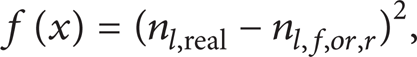
In other words, the process is going to compute the optimum values of four variables that will minimize the squared difference between the target ratio, itrg, and available gear ratio, itot. The objective function is expressed as the squared error between the actual and the desired gear ratios.
An alternative solution for the gear train problem is founded by the differential evolution strategy. These solutions have been found to be globally optimal by applying explicit enumeration as mentioned in Tables 1 and 2 [12–14]. In this paper this problem has been resolved with genetic algorithm for 2009 hummer H3 4dr SUV.
Alternative solution for gear ratio problem [3].

Optimal solution for the gear train problem.

3. 4WD Vehicle Dynamic Gear Ratio
The dynamic gear ratio is obtained with applying dynamic equations as follows [15, 16]:

F f and F r are front and rear traction forces, respectively. m, vehicle mass, a′ is the acceleration, FRR is the rolling resistance force, w is the vehicle weight, θ is the road slope, F A is the aerodynamic force, N f is the front reaction force, N r is the rear reaction force, h A is the height of aerodynamic force, h is the centre of gravity height force, l is the wheel base, and a and b are distances from c.g. to front and rear wheels, respectively. Consider

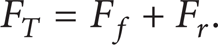
According to Figure 2, the total traction force F T , which is the combination of rear and front traction forces, is defined as

Also


f r is the rolling resistance coefficient. Solving the previous equations gives (4)–(9) as


In a 4WD vehicle, the wheel torques at front and rear axles are distributed such that the ratio of front to rear axle torques is given by r. Assuming that the rear wheels are at the point of slip, an expression is driven for gear ratio of a 4WD vehicle. According to Figure 2, the total traction force is
The equal front and rear gear ratios are obtained by dividing the ratio of traction force of the front and rear axes, which is followed as

Substitution of (5) into (13) will result in

When the rear tyres are at the point of slip, (14) can be written as
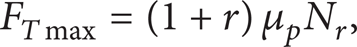
where μ p is the road friction coefficient.
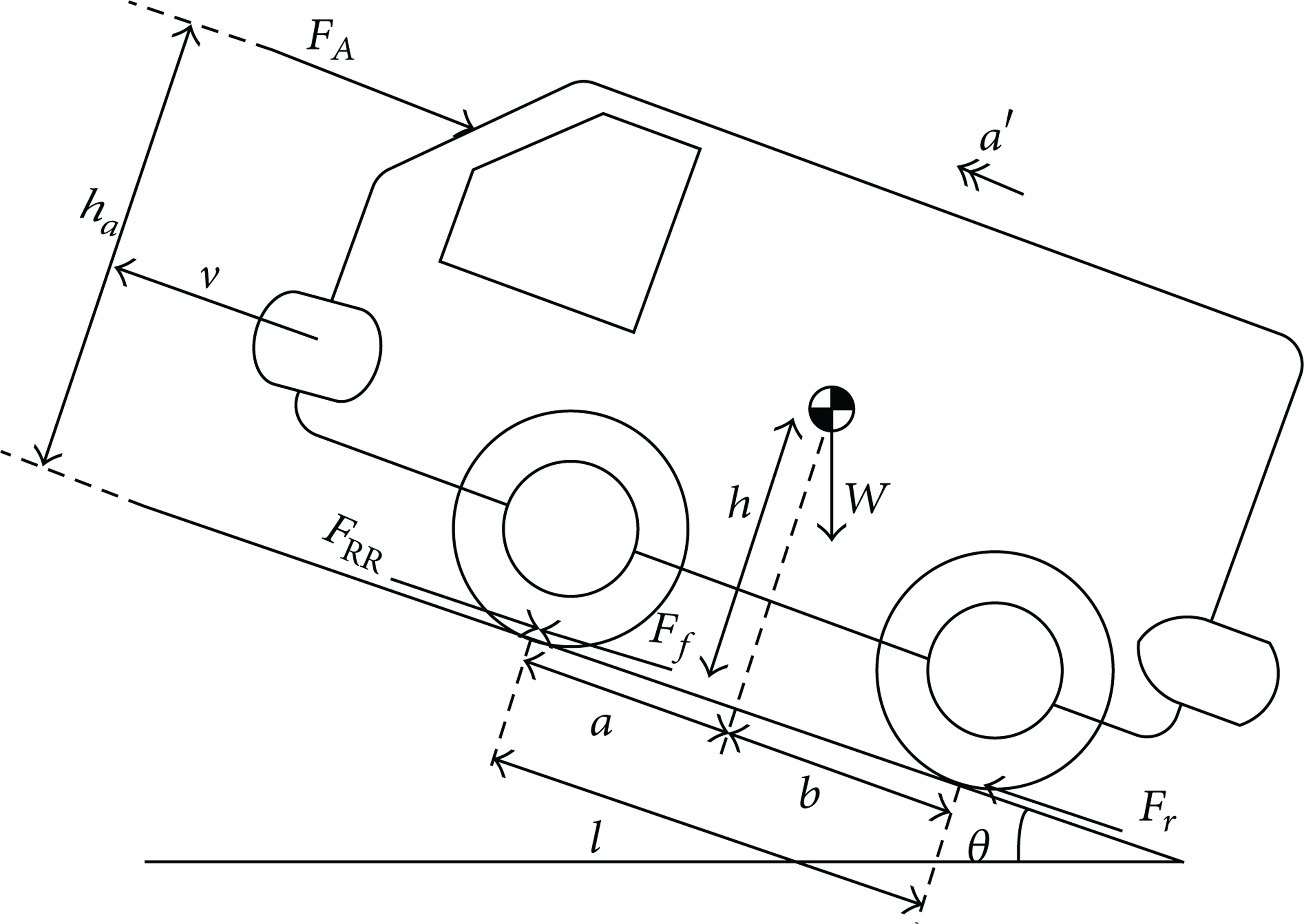
Presentation of a 2D vehicle model.
In this paper, the vehicle velocity is considered equals to zero which happens in the maximum road slope and tyre slip point. Neglecting the term of ΔhF A in (10) and its substitution in (12) leads to
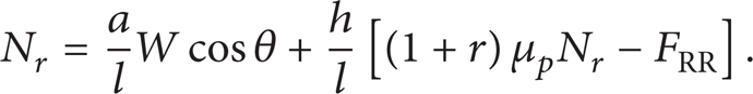
Substituting (8) into (16) and considering
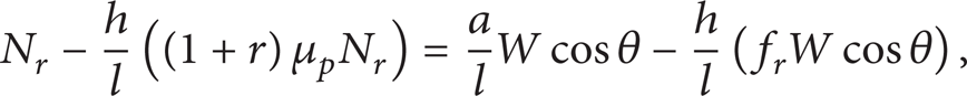

Substituting (16) into (15), the maximum traction force is computed as

The equation of gear ratio (n l ) is presented as
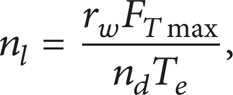
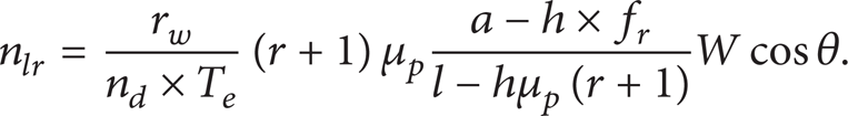
Where n d is the differential ratio, T e is the motor torque, and r w is the tyre radius. Also with substituting (12) into (13) the rear gear ratio (nlr) is obtained as follows:
On the other hand, assuming that the front wheels are at the slip point, an expression for gear ratio of a 4WD vehicle can be obtained. According to (5) and (13) the total traction force can be written as

When the front tyres are at the slip point, the maximum traction force can be computed as

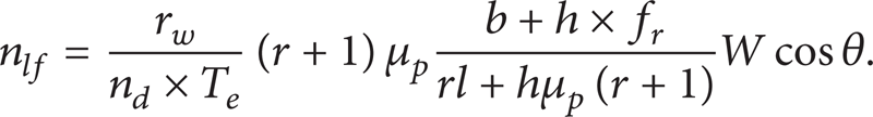
Therefore with substituting the maximum traction force, it can be expressed as

Finally, the front gear ratio is expressed as
The dynamic gear ratio results are compared in two ways. Firstly, a vehicle population including 20 sample cars is compared in such parameters as gear ratio. Secondly, the method was performed to evaluate dynamic gear ratio. The differences between methods are compared with each other. The idea is to show that even the dynamic form, for let us say 70%, is still performing better than the classical form in the case where both of them are used in commercial car.
The values of 1st dynamic gear ratio are compared with those of the 1st classical gear ratio (nl, real) for 20 sample cars that are used by the car factories. This comparison is illustrated in Figure 3. the conventional method does not consider tire slip and the fact that the front or rear tire slip presents different behaviour and makes the calculation more similar to reality. So the dynamic gear ratio is considerably better than the classical gear ratio. Moreover the difference between classical gear ratio and dynamic gear ratio is illustrated in Figure 3. The first gear ratio should be around 4 to 6 to produce more torque in tires. The gear ratios that are proposed in Table 2 are not vehicle ratios and they are used for presenting the classical gear ratio calculation method. The second vehicle gear ratio and other gear ratios reduce to decrease engine torque. The gear ratios of Figure 3 are different from the ratios presented in Table 2 although the same method is utilized in computing vehicle classical gear ratio.
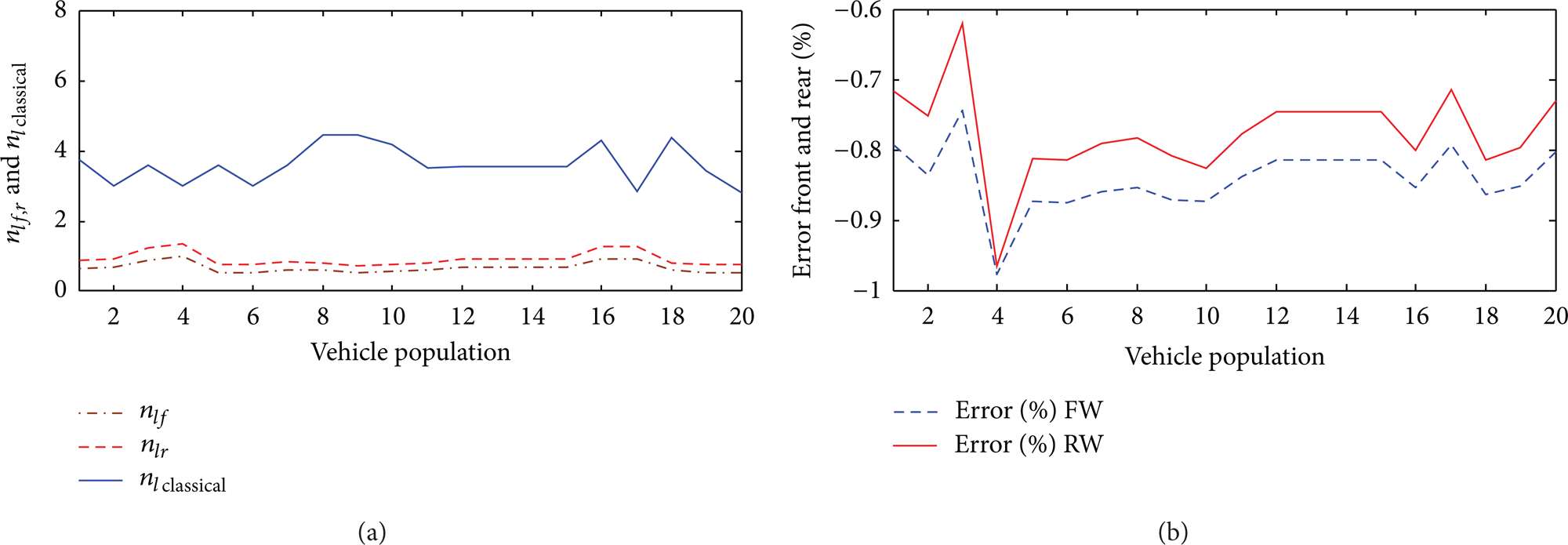
Gear ratio and its error when the front or rear tyres are at slips points.
To optimize the gear ratio in different road slope and for obtaining the optimum basic dimension of 2009 hummer H3 4dr SUV, the effects of gear ratio parameters should be analysed. The effects of basic vehicle dimension variation such as friction coefficient, rolling resistance coefficient, and weight distribution evaluation are studied in Figures 4–6. These figures are utilized for determining the bounds of optimization parameters in the case that the gear ratio error is approximately around zero in each parameter. Moreover, Figures 4–6 indicate the effects of changing parameters such c.g. height of vehicle, μ p , and f r on gear ratio. In addition it would indicate how changing these parameters will change the gear ratios and presents the optimum gear ratio which refers to the point where the errors of parameters are around zero to increase the efficiency of gearbox.
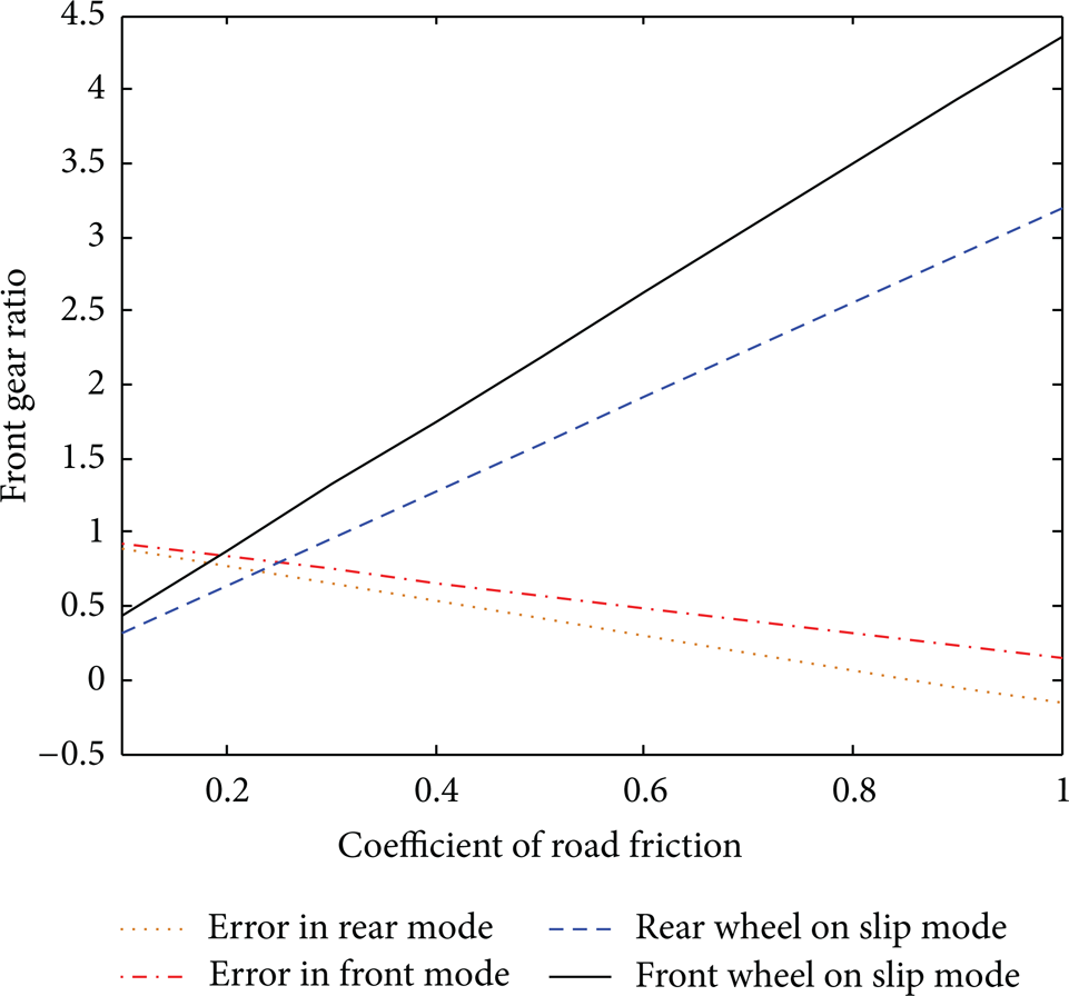
Rear/front gear ratio versus displaying coefficient of road friction.

Relationship between error of rear/front gear ratio and height of vehicle c.g.

Relationship between error of rear/front gear ratio and rolling resistance.
3.1. Coefficient of Road Friction
Coefficient of road friction variation has an effect on the dynamic gear ratio. Its error with classical gear ratio has been shown in Figure 4. As presented in Figure 4, increasing the coefficient of road friction will decrease the difference between classical gear ratio and dynamic gear ratio. In other words, there is a direct relationship between front and rear gear ratios and coefficient of road friction.
3.2. Height of Vehicle c.g
The vehicle c.g. height variation has an effect on the dynamic gear ratio. The error that occurred with classical gear ratio has been shown in Figure 5. As shown, enhancing the c.g. height increases the difference between classic and dynamic gear ratios for frontal mode. On the contrary, this discrepancy will be decreased for rear mode. As a result, front and rear gear ratios have contrariwise effects.
3.3. Rolling Resistance Friction
Rolling resistance, sometimes named rolling friction or rolling drag, is the force resisting the motion when the tire rolls on a surface. It is mainly caused by nonelastic effects; that is, not all of the energy that is needed for deformation of the object is recovered when the pressure is removed. The rolling resistance is presented as a function of velocity, followed as

Figure 6 shows that enhancing the rolling resistance coefficient decreases the difference between classical gear ratio and dynamic gear ratio. Moreover, increasing the rolling resistance enhances front gear ratio.
4. Genetic Algorithm Optimization
Nowadays using evolution methods to solve optimization problems has a growing trend. Genetic algorithms as the most popular evolution algorithms have an extensive application in esearch studies [17–19]. The 1st dynamic gear ratio in the case that front or rear wheels are at the point of slip uses 9 design variables in order to propose an appropriate model of a gear ratio design. The result of the optimization is specifying basic dimensions of vehicle, optimum road slope, 1st gear ratio, and gear train, which minimize the squared difference between the available classical gear ratio, nl, real, and dynamic gear ratio, nl, f, or, r. Genetic algorithm begins with a number of solutions called population. These solutions are represented by strings of gene chromosomes [20, 21]. They are taken from a population of solutions and are used to create new populations, with the thought that the new population is better than the original population. Another term in genetic algorithm is mutation rate. Mutation operator changes the integer parts of strings. Mutation of each string is proportional to the initial objective function (the squared difference between the available classical gear ratio, nl, real, and dynamic gear ratio, nl, f, or, r), which is chosen to fit the mutation rate (Figure 7). This operator can provide a solution that does not exist in the population to compensate loss of valuable information resulting from inadequate intersection. In this paper, the mutation rate, which determines accuracy and speed of convergence response in the GA program, is investigated. The code developed here includes a large number of explorations for different items such as population number, iteration number, value of cost function, and mutation rate. Thus, the minimum value of iteration and speed of convergence are very important. To explore the effect of mutation rate, classical gear ratio of 3.7 is taken. The mutation rates take the values 0, 1%, 4%, 6%, and 15%. An early convergence occurs without any mutation rate, and GA algorithm cannot satisfy all of the possible values of constraints. For the case of 1% mutation the individual bit changes and the chance of achieving better fitness functions increases. While the mutation equals zero, the best fitness function is obtained at 45 generations. However, while the value of mutation rate takes 1%, proper fitness function is obtained at 100 generations. As mentioned, enhancement of the mutation rate value increases the probability of various individuals in the population. Based on this explanation, the mutation rate should be selected between 4% and 6%, which is obtained with trial and error.

Genetic algorithm operator.
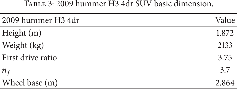
In this paper dynamic gear ratio equation is optimized with genetic algorithm through a diagram that is presented in Figure 8. The objective function is indicated in (27), and it is the squared difference between the available classical gear ratio, nl, real, and dynamic gear ratio, nl, f, or, r. This optimization leads to the benefit of vehicle's parameters such as wheel base and inclination angle as listed before, in Table 3. The best cases of gear ratios for a 4WD vehicle are provided. It is also necessary to introduce randomly chosen variables constrained within specific boundaries. These variables and their band are indicated through (28):

2009 hummer H3 4dr SUV basic dimension.

Genetic algorithm diagram.
4.1. Applying the Genetic Algorithm (GA)
The population size in the gear ratio optimization represents the number of individuals in the population. Usually larger population size increases the amount of variation present in the initial population, and it requires more fitness evaluations. In this case, with a population size of 20, an excellent solution was easily attained. Naturally, a smaller population size will introduce less generations, and the calculation time will be reduced. As presented in Figures 9 and 10, it can be seen that after a sufficient number of generations (around 50 generations), the track for a good (best) solution as well as the track of the average of the population converges to the final solution. Applying genetic algorithm for optimizing basic dimensions of 2009 hummer H3 4dr concludes into optimum data to achieve the most suitable gear ratios. Optimum dimensions of 2009 hummer H3 4dr, noted in Table 4, are suggested in designing the car in order to attain the best dynamic performance.
Optimum dimensions of 2009 hummer H3 4dr.

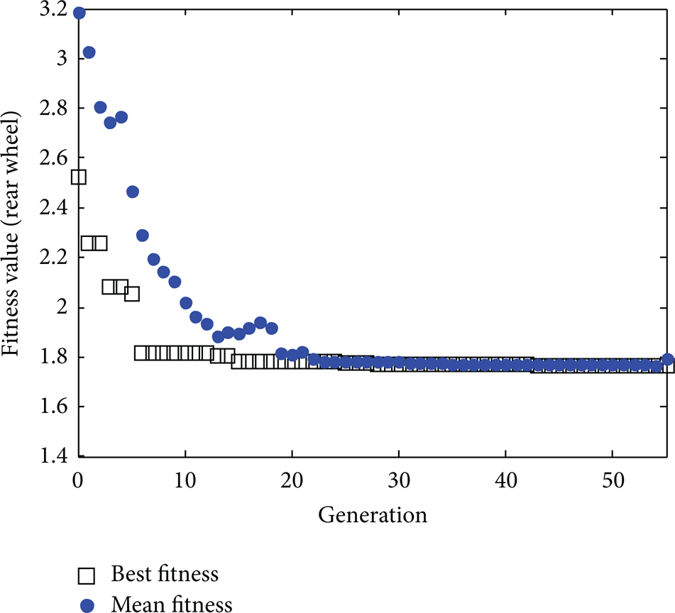
Evolution of the performance for a population = 20 when rear wheel is in slip mode.

Evolution of the performance for a population = 20 when front wheel is in slip mode.
5. Results and Discussion
The results of gear ratio obtained from genetic algorithm are compared with those of conventional methods reported for hummer H3 4dr. This study confirms the results obtained by Godfrey and Babu. The program is capable of finding excellent results for different constraints that are optional and can consider many parameters. In classical form, in order to find the required overall gear ratio, the compound gear train contains two pairs of gears. The second objective function is expressed as the squared error between actual and desired gear ratios. This optimization introduces a gearbox which is obtained from dynamic gear ratio and presents a proper gear ratio. The Godfrey model is based on conventional gear ratio computation which utilizes the classical gear ratio for determining gear tooth. This model is compared with the dynamic model for precise gear tooth. Table 5 expresses number of teeth which is confirmed with results obtained by Godfrey and Babu [3].
Optimal solution for the gear train of 2009 hummer H3 4dr.

The road slope angle is studied in optimized design to introduce the best ratio compatible with environment particularly to make the vehicle perform in a suitable condition. Figure 11 presents an optimum gear ratio in both front and rear slip modes through different road slopes which means that different cities with average road slope need specific gearbox and gear ratios.

Optimum front and rear gear ratios for different road slope angles.
6. Conclusion
In this paper two issues related to automotive gear ratio have been considered. Firstly, the traditional trial and error approach is presented to calculate the gear ratio based on discovering combination of gear teeth numbers which satisfy the geometric constraints.
Secondly, the dynamic gear ratios are computed with the aid of dynamic parameters of a vehicle. Then, comparing the presented results with those of traditional gear ratio design shows the superiority of this research for a commercial car.
Then, a new method is developed to calculate the first gear ratio which has a tendency to minimize the difference between dynamic gear ratio and classical gear ratio. Therefore, dynamic equations for calculating gear ratio have been overstated to study the first gear ratio for optimizing basic dimensions of a sample car (2009 hummer H3 4dr). The presented method was also used to evaluate the optimum dimensions of a vehicle to achieve the minimum differences of classical and dynamic gear ratios. It is also concluded that more road slope yields low first gear ratio due to the effect of c.g. height. The results are also compared with those reported by Godfrey and Babu [3]. Comparing the results shows the reliability of the presented research. The presented algorithm has the high flexibility in comparison with the conventional one. It is more adaptive to get the best gear ratios where dynamic constraints are of high importance. Moreover, this paper indicates the effects of changing parameters such as c.g. height of vehicle, μ p , and f r on gear ratio. The presented diagrams are used for determining the bounds of optimization parameters in the case that the gear ratio error is approximately around zero in each parameter. Moreover, the equations of front and rear gear ratios indicate that two parameters of wheel base length and engine torque play an important role to achieve the suitable performance.