
Abstract
As consumers increase the level of quality requirements for foods due to the spread of well-being culture, the demands for safe cold chain have been continuously increased. However, as we can see from the food poisoning incidents that have recently occurred, important issues are how to keep the items (foods) and manage them. Although many people are aware that these issues are important, development and investment for keeping and managing foods are not enough at present. In the existing cold chain system, it is seen that the technologies of ubiquitous sensor networks (USNs), GPS, and CDMA have been used. However, this is only applied to a particular area, and the refrigeration/freezing level is the same as the existing one. In this paper, in order to increase the utilization of the cold chain system, we use both the commercial technologies of sensors and ZigBee for environmental measurements and cellular phone or smart phone with GPS for real-time localization and date transmissions. It is expected that our implementation system that is instantly ready to use leads to the expansion of cold chain system to various fields and the development of USN technologies.
1. Introduction
Recently, as the quality of requirements for consumer increases due to the well-being culture, the demand for safety in cold chain system has been increased. In the case of foods, how to deliver from the producer to the consumer's home influences the price of the products. Consequently, the manufacturers or distributors of the products prefer high quality of logistics services that can be passed to the consumer in the optimal condition to the existing one.
Due to the fact that foods are directly related to the health of consumers, keeping the products (foods) and managing them in the appropriate environmental conditions are very important in logistics system. Therefore, the logistics companies use 3rd Party Logistics (3PL) for efficient and reliable logistics. Although some of companies use the technologies of RFID, USN, and GPS in 3PL, because of the setup costs and the limitation of technology, most companies cannot apply the location based information monitoring system [1–3].
In this paper, we propose the method which is efficiently applied to cold chain system by using the technologies of USN, ZigBee, GPS, and mobile communications (CDMA or LTE). In Section 2, we briefly introduce the technologies related to USN. Then, we introduce our proposed system in Section 3. Performance evaluation is followed in Section 4. Finally, we conclude this paper in Section 5.
2. Related Technology
In the cold chain system, real-time monitoring gathers the location and status (e.g., temperature and humidity) of moving object by using sensors ZigBee, localization, and information transfer technology. Also, we need a control system for tracking the status in order to monitor the information gathered at anytime and anywhere. Several localization algorithms and monitoring methods protocols have been proposed in USN [4–17]. In this section, we briefly overview USN, ZigBee, and existing cold chain systems.
2.1. Sensor Network
2.1.1. USN
A sensor network consists of spatially distributed nodes to monitor physical or environmental conditions. Basically, sensor nodes are distributed in dense, and they configure the network topology by themselves. Due to the limitation of battery life of sensors, the sensor network usually uses the energy-dependent routing method. In general, sensor network has the system structure [1, 18, 19] as shown in Figure 1.

A sensor network system.
In a sensor network, a sink node is connected to the Internet through wireless or wired medium. A user generally requests sensing information in the sensing environment to the sink node such that it gathers environmental information from the sensors distributed in a sensor network. USN sensor nodes are mainly tiny, with low consumed power and low cost. However, based on the purpose, sensor nodes have different characteristics compared to the usual sensors. In a sensor network, it uses IEEE 802.15.4/ZigBee protocol for wireless communications. Note that this standard supports low-power system and 250 kbps transmission rate at maximum. In recent, IP-USN based on IPv6 has been used.
2.1.2. ZigBee
ZigBee is based on IEEE 802.15.4 to support low power consumption and low cost. IEEE 802.15.4 is the international standard for short-range wireless personal communications. ZigBee specifies the physical layer, Medium Access Control (MAC), Network application layers (NWK), application service layer, security, and application layer, respectively. It is emphasized here that this ZigBee is suitable for remote control, remote management, and remote monitoring so that it is widely applied to home automation, factory automation, and industrial automation. Also, ZigBee supports the mesh network, which is suitable in sensor network. In other words, this ZigBee is suitable in complex systems. Figure 2 depicts the network layers for ZigBee.

Network hierarchy at ZigBee system.
ZigBee uses the frequency bands usually at 2.4 GHz, 915 MHz, and 868 MHz with 16 channels at 2.4 GHz, 10 channels at 915 MHz, and only 1 channel at 868 MHz. Figure 3 shows the channels with respect to the frequency bands [20].

2.2. Cold Chain System
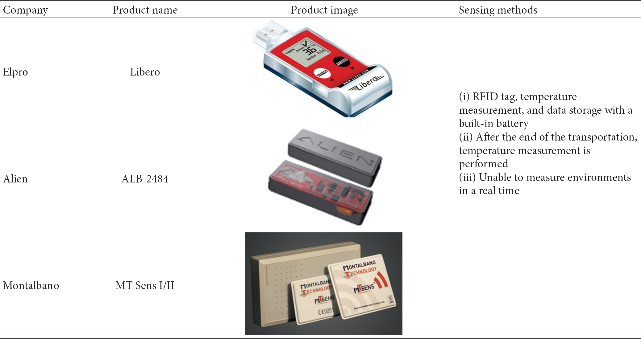
In a cold chain system, there are differences in the retention methods for the stability of the products according to the temperature changes and the refrigerated and frozen products. In order to increase the product reliability, there are two types of monitoring methods. (1) The first one is the way to monitor the real-time temperature in the moving environment. In this case, when the products are arrived at the destination, wireless network technology is usually used to transfer the information to the server. (2) The second method is to transfer the environmental sensing information to the server through the mobile network in real time. Table 1 shows the products related to the cold chain system.
Major research and development for cold chain system.
3. Real-Time Localization and Environmental Monitoring
Our proposed system is composed of two parts: (i) environmental monitoring and (ii) real-time communication for transferring sensing data and localization information to remote area. In order to monitor the environments, we use the ZigBee-based sensor module for temperature and humidity. For real-time data communication and localization, a mobile communication network and GPS module of smart devices are used. Figure 4 shows the basic system structure of our proposed system.
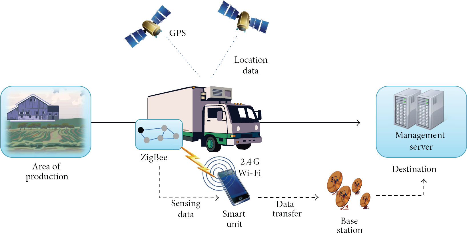
Overall system structure of our proposed system.
In the proposed system, ZigBee-based sensor module attached to the delivery vehicles and the set-top box that is used as a sink node collect the status of products in the vehicle and the temperature and humidity condition in the interior of the vehicle. Then, this information is transmitted to the smart devices through wireless networks. At the smart devices, it transmits both the location information obtained by GPS and sensing information to the administrative server through mobile communication networks. All information collected at each basement is being gathered through the middleware of the management system, and it is viewed and managed through the applications. In addition, the administrator can pass the control command through the mobile communication network to the delivery vehicle when needed. By using the control commands, it is possible to adaptively change the transmission rate between the set-top box and the administrator. Also, we can instantly obtain the status of the products and GPS location information at the request of the administrator.
When the delivery vehicle arrives at the destination, the set-top box transmits all information gathered during the delivery to the management system through the wireless network.
3.1. ZigBee-Based Sensor Module and Set-Top Box
ZigBee-based sensor module and set-top box mainly performs gathering temperature, humidity, and the other sensing information of the delivery vehicles. In general, both ZigBee in the set-top box and RF communication by using the sensor module are used for gathering the information. Sensor modules are distributed inside and outside of product box according to the environment of the vehicles or the characteristics of the products such that all sensing data gathered are transferred to the set-top box through RF communication in ZigBee. Figure 5 depicts the block diagram for ZigBee-based sensor module.
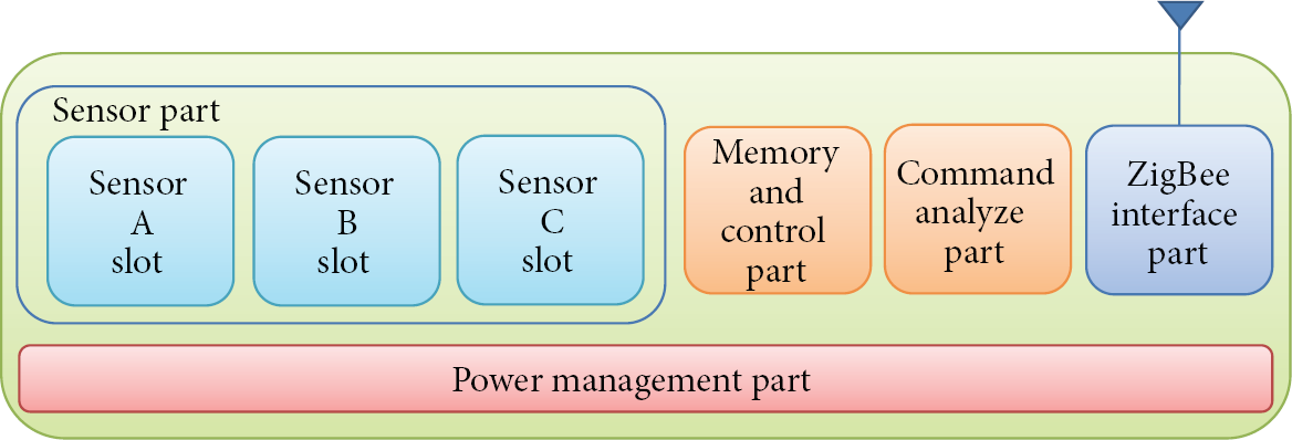
Block diagram for ZigBee-based sensor module.
Sensor module has many parts for power management, environment sensors (temperature, humidity, and lighting), transmission for sensing data through RF communication of ZigBee, receiving the control command from the set-top box, and the control part for flow control.
Figure 6 shows the block diagram for the set-top box. The set-top box as a sink node among the sensor modules is similar to the sensor module while it extends the size of the memory to save all sensing data gathered during the delivery and the wireless networking part to communicate with the smart devices.

Block diagram for the set-top box.
3.2. Protocol for RF and Wireless Network
We use RF communication between ZigBee-based sensor module and set-top box while we use a wireless networking between set-top box and smart devices to transfer data and control command. For these two types of communications, we need to define the packet format for handling the data and the control command. Table 2 shows the packet format for RF and wireless networking communications.
RF and wireless network protocol.

Each information of the packet is as follows:
(i) STX: start of text (start 0x02);
(ii) Length: the data length for Command 1 to Check-Sum;
(iii) Cmd1: sender unit
→M: management server,
→S: smart unit,
→B: set-top box,
→Z: ZigBee sensor module,
(iv) Cmd2: receive unit (same Cmd1's text);
(v) Cmd3: T→request, R→response;
(vi) Cmd4: function;
(vii) S_ID: sender ID;
(viii) R_ID: receiver ID;
(ix) Data: sensing data and command data fields;
(x) Status: RF channel (0–127) and battery check fields;
(xi) Check-Sum: error checking;
(xii) ETX: end of text (end 0x03).
3.3. Location Information and Data Communication
We can obtain the location information of the delivery vehicle such as the latitude, the longitude, and the speed of the vehicle by using the GPS module in the smart devices. Figure 7 indicates the process of obtaining location information through GPS and Wi-Fi in the Android platform.
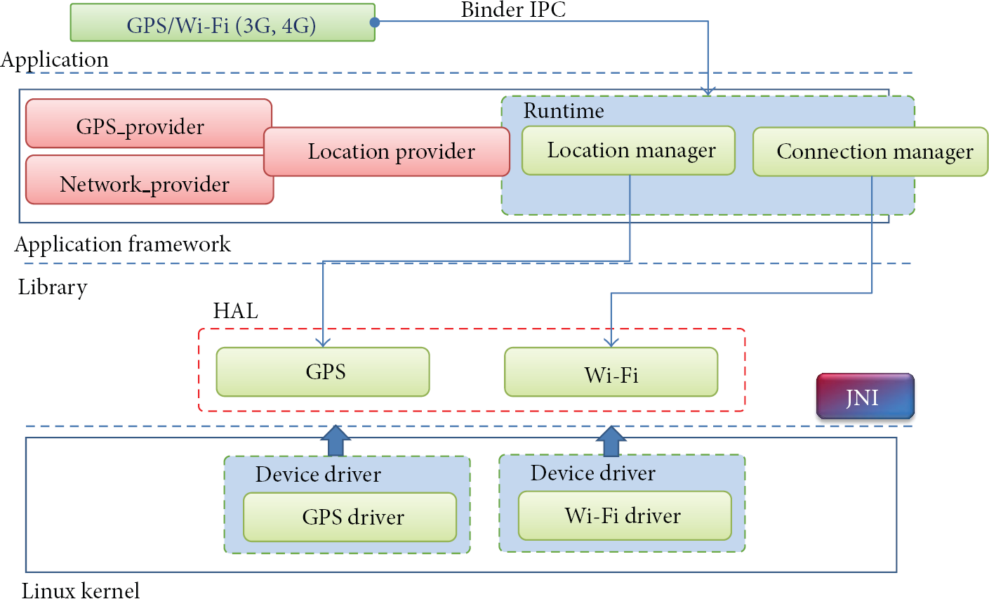
Process for obtaining location information in Android platform.
Note that the collected information can be transmitted through mobile communications and Wi-Fi. Also, when the vehicle arrives at the destination, all collected data at the delivery vehicle can be verified by comparing real-time data stored in the server. For example, in the Android platform, GPS_provider and Network_provider are used for obtaining the location information. For the communication between the set-top box and administrative server, wireless network and/or mobile communication networks are used.
4. Performance Evaluation
In order to verify the performance of the proposed system, we first measure the communication sensitivity of temperature and humidity from ZigBee-based sensor modules. We also check the RF communication sensitivity between the set-top box and sensor modules. Figure 8 shows the RSSI value when the RF coaxial cable of signal generator is directly connected while the sensor module and the antenna of the set-top box are removed. In the measurement of RSSI value, as the signal power of RF input power increases, the corresponding RSSI values relatively increase, we can increase the communication range for the high RF output power. Consequently, and we can cover all the area of the vehicle.

RSSI value with respect to RF input power.
In order to measure the performance of the sensor modules for temperature and humidity, we first measure the change of temperature and humidity in enclosed area. Also, we check whether the sensing data has been accurately transferred by comparing the data transmitted over wireless networks from the smart devices. Figure 8 shows the results of the comparison between the sensing data measured at sensor modules and the data transferred at smart devices on an hourly basis.
Figure 9 shows the comparative results for the data obtained at the sensor module and the data saved at the smart devices through the set-top box. In this experiment, if these two values are the same, 0 is showed up. In contrast, if there are some errors, we can see the measurement value. At 16 seconds, we can see the difference between the data saved by smart devices and by the set-top box. This is due to the fact that the measurement of the data length is wrong so that some parts are ignored during the data analysis process.

The data comparison for temperature and humidity at sensor modules and smart devices.
5. Conclusion
In this paper, we proposed the method for gathering environmental information such as temperature and humidity by using the sensors and transferring the data to the administrative server in the remote area. We believe that the proposed method can improve the utilization of the cold chain system and its applications. For the measurements of environmental data, we use commercial temperature and humidity sensors and ZigBee technology. We also use the GPS technology of the smart devices for obtaining the location information, and mobile communication technology for data communication. Through the various experiments, we verify the overall effectiveness for RF communication between ZigBee based sensor module and set-top box. With the combination of the technologies, we can improve the applicable areas of the cold chain system.
Footnotes
Acknowledgment
This work was supported by an Academic Research Fund of Chungwoon University in 2013.