
Abstract
The design theory and method of formed milling cutter for double-helix screw of progressing cavity pump are presented. Through analyzing the shape and characteristic parameters of double-helix screw, the helicoids equation and axial curve equation of double-helix screw were established. According to the relative position relations between formed milling cutter and double-helix screw in the machining process, the geometric mapping relationship of screw coordinate system and formed milling cutter coordinate system was established by using the coordinate transformation theory. Based on noninstantaneous envelope method and the meshing conditions between formed milling cutter and double-helix screw, the contact line equations were established by minimum value method. By analyzing the machining errors caused by resharpening the formed milling cutter, the tooth back curve equation was established based on spiral of Archimedes, and the profile equation of formed milling cutter with constant back angle was got. On this basis, the formed milling cutter of processing double-helix screw was designed, and the cutter head and tool post were manufactured, respectively. The measuring results have shown that this method can satisfy the requirements of machining accuracy for double-helix screw. So this is an effective method to get formed milling cutter profile for double-helix screw.
1. Introduction
With the difficulties increasing in oil exploitation, the traditional oil extraction equipment cannot satisfy the requirements of oil production. As one of the rising oil extraction equipment, the progressing cavity pump has been gradually applied in the oilfield exploitation with its superior performance. At present, the single-head progressing cavity pump is used in most oil field. However, theoretical calculation and experimental study show that the double-helix progressing cavity pump has more superior performance than the single-head progressing cavity pump. The output capacity of double-helix progressing cavity pump is greatly increased under the same structural parameters. Under the condition of same output capacity, its structure parameters correspondingly decreased. It is advantageous for improving the stress of rubber stator and prolonging the service life of progressing cavity pump. Therefore, the double-helix progressing cavity pump is the main development trend and research direction of progressing cavity pump [1, 2].
Double-helix screw is a key part of the double-helix progressing cavity pump. Its curved shape and machining quality decide the technical performance indicators of progressing cavity pump, such as the meshing condition of the screw and spiral cavity, working pressure, rated flow, volumetric efficiency, and vibration noise. Therefore, the performance of progressing cavity pump depends on the design and manufacture of double-helix screw. There are many kinds of processing methods of screw, and they mainly include milling, hobbing, and grinding. The milling machining is most widely used, because of its high efficiency and good stability [3–7]. In screw milling processing, the precise calculation of cutter profile for formed milling cutter is the key to realize high precision machining, and it is also the foundation of manufacturing formed milling cutter [8–11]. According to the characteristic parameters of progressing cavity pump, Mimmi and Pennacchi had established the screw model and determined the contact line between cutter and screw to get the cutter profile [12]. And they analyzed the screw processing error which was caused by cutter wear [13]. Using the analytic method of coordinate transformation to design the cutter profile of rotary milling, Mohan and Shunmugam solved the over cutting problem of the screw [14]. Using multiple inserted cutter blades in roughing screw, Chiang and Fong established multiple insertion models to process screw, so that each blade of milling cutter has the same wear rate [15]. According to the envelop principle of milling cutter rolling surface and the spiral surface, Wu et al. had achieved the design on the contour of milling cutter in machining complex spiral surface [16]. According to the discrete point data on spiral surface work piece, Zhang had calculated mathematical model of formed milling cutter profile and analyzed the calculation error of formed milling cutter [17]. With the characteristics that the space position of contact line is unchanged, Peng et al. had deduced the geometry condition of helicoids space contact, and it had been applied to the design of screw hob blade [18].
Based on the above issues, a design method of formed milling cutter for double-helix screw of progressing cavity pump is proposed. Firstly, the helicoids equation and the axial curve equation of double-helix screw were established. Secondly, based on the noninstantaneous envelope method and minimum value method, the basic profile equation of formed milling cutter was established. By analyzing of machining error caused by resharpening formed milling cutter, the tooth back curve equation of formed milling cutter was established, and formed milling cutter profile equation with constant back angle was got. Finally, the design and manufacture of formed milling cutter are done to verify the design correctness.
2. Parametric Modeling of Double-Helix Screw
2.1. Helicoids Equation of Double-Helix Screw
Two semicircles and two straight lines form a long circle, and it spirally rises to form a spiral surface which is the surface of double-helix screw. The fixed coordinate system oxyz and the dynamic coordinate system ox1y1z1 of double-helix screw are shown in Figure 1. The initial position of two coordinate systems is shown in Figure 1 (a), and they are superposition. In Figure 1 (a), the coordinate axes x and x1 are along the end face short axis direction of double-helix screw, the coordinate axes y and y1 are along the end face long axis direction of double-helix screw, and the coordinate axes z and z1 are along the center axis direction of double-helix screw which is perpendicular to the plane xoy. Figure 1 (b) is the position of dynamic coordinate system ox1y1z1 which is formed by rotating around the coordinate system axis z1 clockwise with angle φ.

Coordinate systems of double-helix screw. (a) Initial position of two coordinate systems. (b) Position of dynamic coordinate system rotated clockwise angle φ.
In order to find the helicoids equation of double-helix screw, the end face equation of double-helix screw must be established at first. Then the end face equation spiral rotates around the axis z with lead T to get helicoids equation [19, 20]. It can be seen that the end face of double-helix screw is symmetric for axes x and y in Figure 1. So we need to find the equation of curve BCD. The curve BCD is composed of circular arc BC and straight line CD. So the end face equation of double-helix screw can be got as long as we establish equations of circular arc BC and straight line CD.
On the end face of double-helix screw, the lengths of lines AG and CE are 2b, the lengths of lines AC and GE are 2a, the radii of circular arcs ABC and EFG are a, and the included angle of line oC and axis y is
Take any point N1(x, y, z) on circular arc BC. From the position relations in Figure 1, the surface equation of double-helix screw which is formed by circular arc BC can be got as follows:
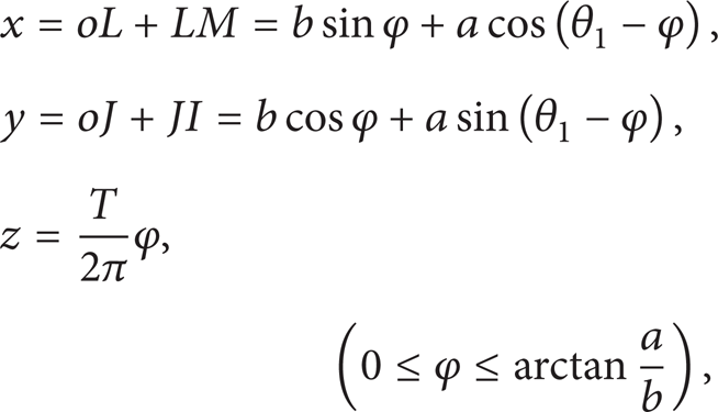
where θ1 is included angle of N1K and axis ox1, which is between
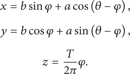
Take any point N2(x, y, z) on straight line CD. From the position relations in Figure 1, the surface equation of double-helix screw which is formed by straight line CD can be got as follows:

where θ2 is included angle of oN2 and axis ox1 and
The helicoids equation of double-helix screw can be got from formulas (1) and (2).
When
When
2.2. Axial Curve Equation of Double-Helix Screw
The double-helix screw is split along center axis with plane. The intersecting line of the plane and helicoids is the axial curve of double-helix screw. The axial curve equation solving is divided into two parts because the helicoids equation of double-helix screw is divided into two parts with the range of angle φ.
When

The axial curve of double-helix screw was got by splitting the helicoids with plane yoz. Let x = 0 in formula (5); the axial curve equation of double-helix screw is got as follows:

When

Let x = 0 in formula (7); the axial curve equation of double-helix screw can be got:

The axial curve equation of double-helix screw can be got from formulas (6) and (8). The axial curve of double-helix screw can be got as shown in Figure 2.

Axial curve of double-helix screw.
3. Modeling of Formed Milling Cutter Profile Equation
3.1. The Noninstantaneous Envelope Method
The noninstantaneous envelope method is a kind of processing method. It will do relative movement between milling cutter and work piece to form surface of work piece. In recent years, noninstantaneous envelope technology has combined with numerical control technology. It has been widely used in kinds of surface machining, such as helical surface and free-form surface. It can machine the workpieces which are more and more complicated.
The formed milling cutter is a special tool for processing forming surface. The cutting edge of formed milling cutter is needed to be designed based on the workpiece surface. According to noninstantaneous envelope method, when formed milling cutter processes helicoids, formed milling cutter will do helical motion to get the envelope surface which is the helicoids of work piece. It can be seen that the surface of formed milling cutter and the helicoids of work piece is tangent along a space curve, and this space curve is called contact line. Therefore, by rotating the contact line around the cutter axis, the rotary surface of formed milling cutter can be got. Then the cutting edge of formed milling cutter can be got by taking the axial section of rotary surface.
3.2. The Geometric Mapping Relationship of Double-Helix Screw and Formed Milling Cutter Coordinate Systems
The coordinate systems of double-helix screw and formed milling cutter were established as shown in Figure 3. The coordinate system of double-helix screw is oxyz, its origin is the end face center of double-helix screw, and its z-axis and center axis of double-helix screw are overlapped. The coordinate system of formed milling cutter is o c x c y c z c , its origin is the rotation center of formed milling cutter central plane, and z c -axis and cutter axis of formed milling are overlapped. The x-axis in coordinate system of double-helix screw and x c -axis in coordinate system of formed milling cutter are overlapped, and they have the same direction [21–24].
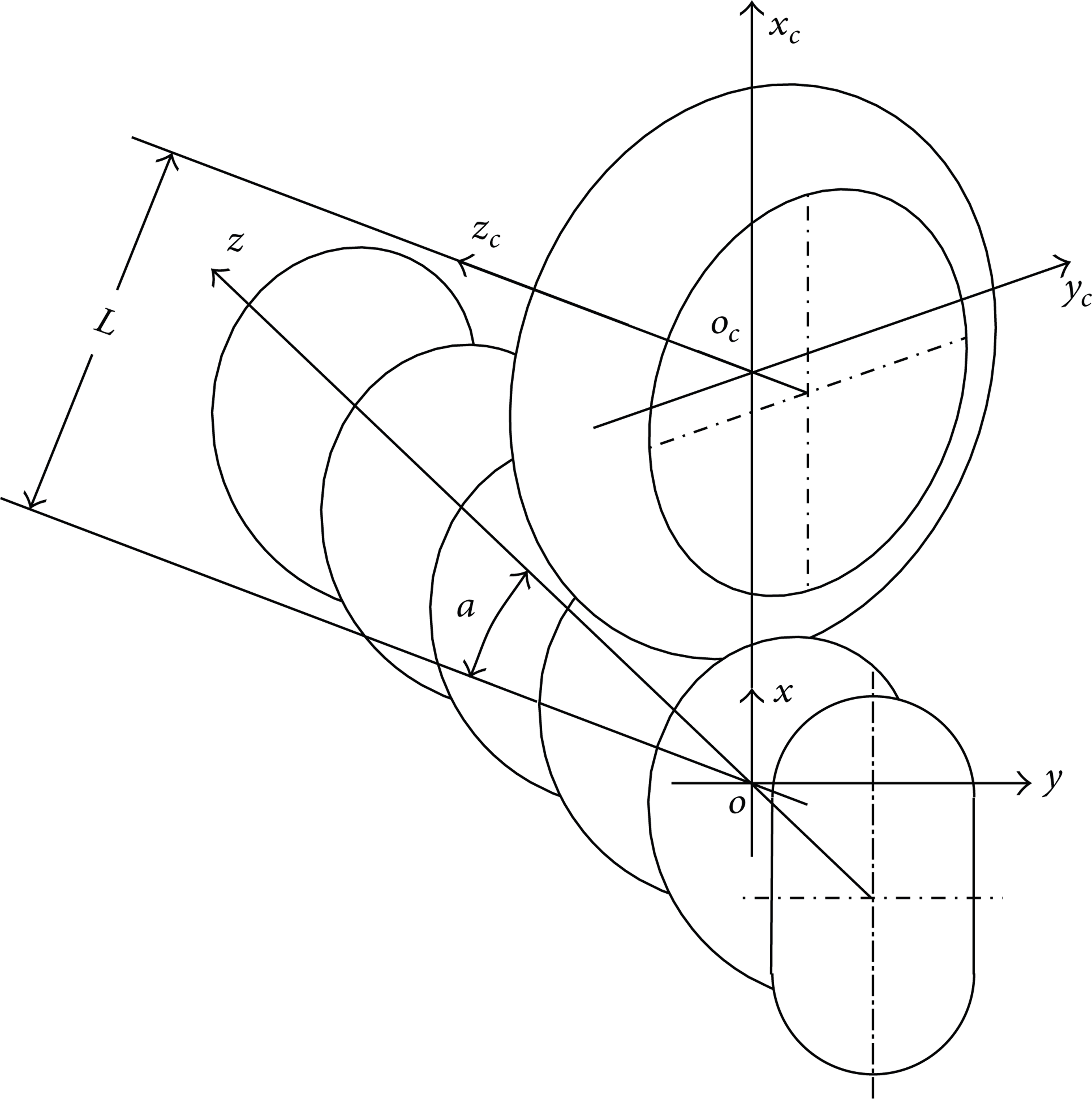
Coordinate systems of formed milling cutter and double-helix screw.
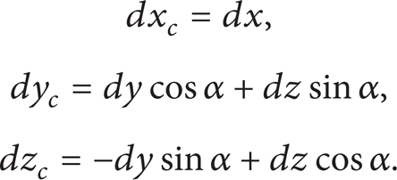
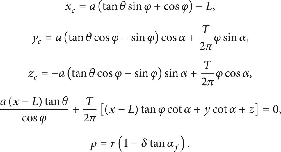
The two coordinate systems will not turn with the rotation of double-helix screw and formed milling cutter. Therefore, their space locations are fixed. Suppose the shortest distance between the formed milling cutter center axis and the double-helix screw center axis is L and the angle between the two axes is α. The coordinate transformation between two coordinates is expressed as follows:
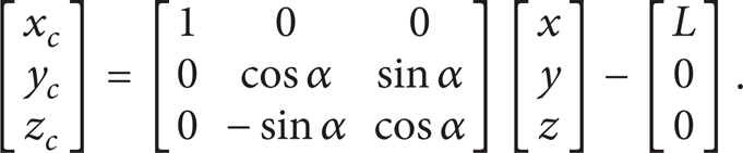
Thus the geometric mapping relationship of the two coordinate systems is

3.3. Contact Conditions of Formed Milling Cutter and Double-Helix Screw
According to the profile design principle of formed milling cutter, the contact conditions of tool rotary surface and screw helicoids are got with section method. A section of P – P is made, which is perpendicular to the center axis of formed milling cutter and parallel to the central plane x c o c y c with the distance d. It is shown in Figure 4. It can be seen from Figure 5 that the intersecting line between section P – P and tool rotary surface is a circle C, and the intersecting line between section P – P and screw helicoids is a plane curve I. Because the tool rotary surface and screw helicoids are tangent, the circle C and the plane curve I will be tangent at a point. The intersection N between circle C and plane curve I is the point of tangency; namely, the intersection N is the contact point between the contact line of tool rotary surface and screw helicoids.
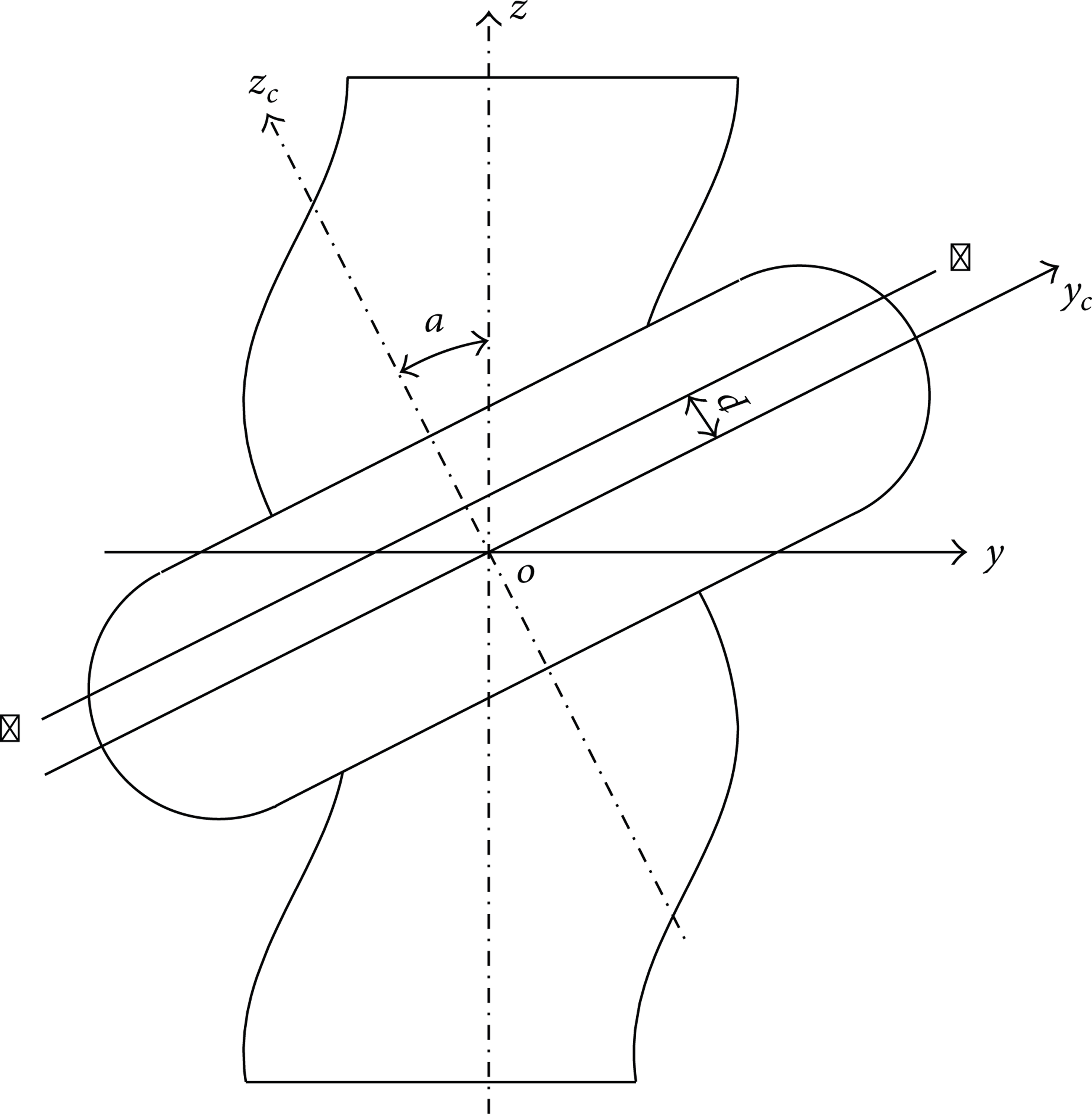
Projection drawing of formed milling cutter and double-helix screw.
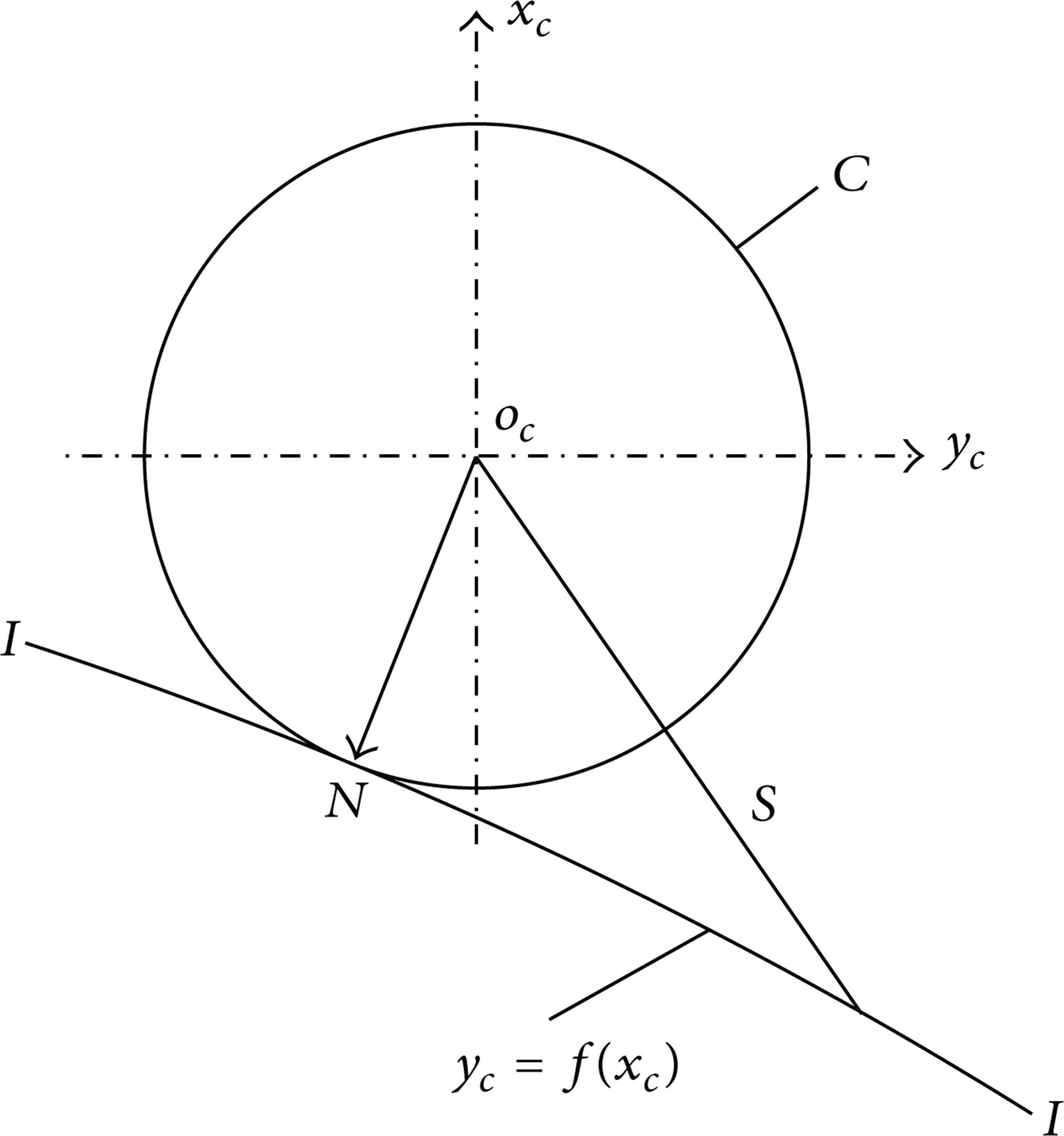
Sectional view of section P – P.
3.4. Contact Equation of Formed Milling Cutter and Double-Helix Screw
Suppose the distance d between section P – P and plane x c o c y c is a constant. The formula about geometric mapping relationship between the two coordinate systems can be expressed as

The total differential equation of formula (11) can be got as follow

From the formula (12) can be got formula (13):
Suppose the equation of plane curve I in coordinate system of formed milling cutter o c x c y c z c is

Suppose the distance from arbitrary point on the plane curve I to the center axis of formed milling cutter is S; then

In the formula (15), S is a unary function of x c . According to the tangent conditions of the circle C and the plane curve I, the radius of circle C is the minimum of function S. It takes one number of derivatives for formula (15), and let it be equal to zero:


According to the range of angle φ, the helicoids equation of double-helix screw is divided into two parts. Therefore, the contact line equation of tool rotary surface and screw helicoids is solved in two parts.
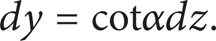
When

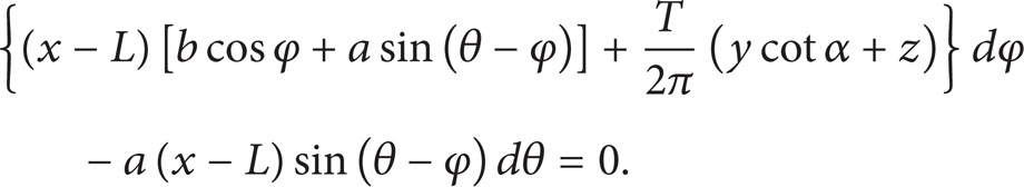
The relation between dθ and dφ can be got as shown in formula (19) by putting dy and dz in the formula (18) into formula (13):

The total differential equation of formula (10) is
Formula (21) can be got by putting formula (13) into the second formula in formula (20)

Formula (22) can be got by putting formula (10), formula (18), formula (20), and formula (21) into formula (17):
When

When

The relation between dθ and dφ can be got as shown in formula (25) by putting dy and dz in formula (24) into formula (13):

Formula (26) can be got by putting formula (10), formula (20), formula (21), and formula (24) into formula (17) to get

When

In formulas (23) and (27), L, T, a, b, and α are constant, and x, y, and z are the functions about parametric φ and θ. Therefore, the contact line equation of tool rotary surface and screw helicoids is about the parametric φ and θ.
Using MATLAB simulation, the contact line of tool rotary surface and screw helicoids can be got as shown in Figure 6.

Contact line of formed milling cutter and double-helix screw.
3.5. Basic Profile Equation of Formed Milling Cutter
It can be known from the contact line equation of tool rotary surface and screw helicoids that the value of φ can be worked out by one given value of θ. This means that the point in the cross-section of double-helix screw will become the contact point after being turned an angle φ. Then the coordinate (x c , y c , z c ) of contact point in the tool coordinate system can be got by putting value (φ, θ) into formula (3), formula (4), and formula (10). According to the parameters scope of cross-section of double-helix screw, it can get the axial cross-section shape of tool rotary surface, which is the basic profile equation of formed milling cutter.
When
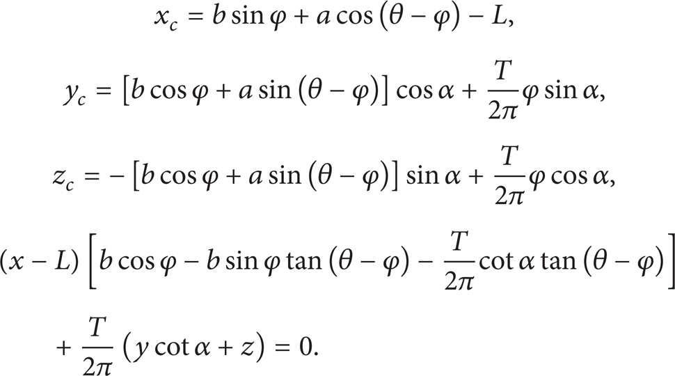
When

Using MATLAB simulation, the basic profile of formed milling cutter can be got as shown in Figure 7.

Basic profile of formed milling cutter.
3.6. Tooth Back Curve Equation of Formed Milling Cutter
After resharpening the cutter edge of formed milling cutter, the diameter of formed milling cutter will be reduced. The machining errors will be produced because the shortest distance L between tool axis and screw axis decreases, caused by decrease of cutter diameter. Therefore, the profile of formed milling cutter should be changed with it. A profile equation which has a constant back angle is established, that is to say that the tooth back curve has constant back angle by the establishment of the tooth back equation. The back angle of formed milling cutter will remain unchanged after it is being resharpened. Theoretically the logarithmic spiral can satisfy these requirements, but the manufacture of logarithmic spiral is very difficult. Therefore, it will use spiral of Archimedes as the tooth back curve.
The radius vector ρ of every point on spiral of Archimedes will be added or reduced proportionally with its rotor angle δ. It can be seen from Figure 8, ρ equals to r when δ equals to zero; ρ is lesser than r when δ is greater than zero, where r is radius of formed milling cutter. Therefore, the normal equation of spiral of Archimedes is

where c is constant.

Spiral of Archimedes.
The included angle γ between the tangent and the radius vector of arbitrary point B on the tooth back curve can be got as follows:

The back angle of tooth back curve is expressed as α f , and α f = γ – 90°. So
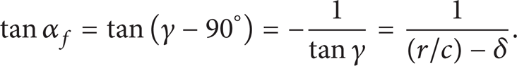
By formula (32), the back angle α f will increase gradually with increased angle δ. However, the increased amount is very small, and it can be ignored. So we can think that the back angle of formed milling cutter is constant.
When δ = 0°, formula (33) can be got from formula (32):
The equation of tooth back curve is

3.7. Profile Equation of Formed Milling Cutter
According to the basic profile equation of formed milling cutter and the tooth back curve equation, the profile equation with constant back angle can be obtained.
When

When
Using MATLAB simulation, the profile surface of formed milling cutter can be got as shown in Figure 9.
Profile surface of formed milling cutter.
4. Experimental Results and Analysis
According to the screw numerical control milling machine and the actual processing conditions, the formed milling cutter manufacture structure is separated into the cutter head part and tool post part, and the formed milling cutter physical display is shown in Figure 10. The structure allows the cutter head and the tool post to use different materials. This structure guarantees that the high speed steel is used on the blade to reduce production cost. According to the profile equation of formed milling cutter for double-helix screw and the specific parameters, the cutting edge and profile of formed milling cutter can be got by calculation. It will ensure that the helicoids of double-helix screw can be machined correctly and the formed milling cutter has constant back angle. When the formed milling cutter becomes dull, the cutting edge shape remains unchanged after resharpening, and it will improve the service life of formed milling cutting.

Formed milling cutter.
The experiment was carried out in order to verify the correctness of the profile equation of formed milling cutter for double-helix screw. The formed milling cutter was installed on numerical control milling machine to process work pieces, and it is shown in Figure 11. By checking every parameters of double-helix screw, the correctness of design method can be verified.

Processing double-helix screw.
In order to assess the machining precision and accuracy of double-helix screw, it measures the end face and the axial curve of double-helix screw with three coordinate measuring machines. The results were compared with the theoretical value of the end face and axial curve, and the contrast results are shown in Figures 12 and 13. In Figures 12 and 13, the solid line denotes the actual processing results and the outside and inside dotted lines, respectively, express the upper tolerance and lower tolerance borders ofthe end face and axial curve with magnifying 250 times. The upper tolerance is +0.02 mm, and lower tolerance is –0.02 mm.
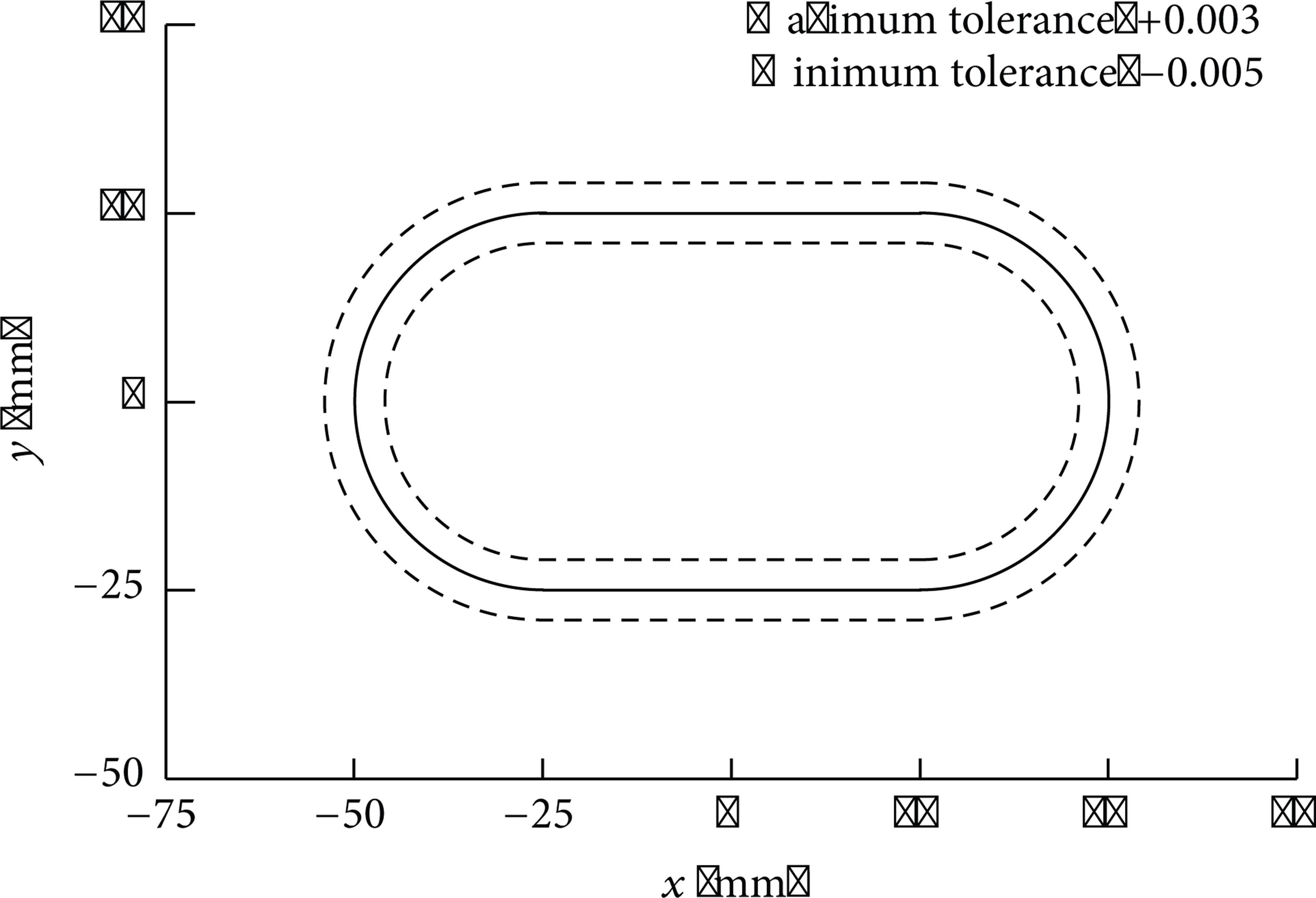
Comparison of the end face and the theoretical lines.
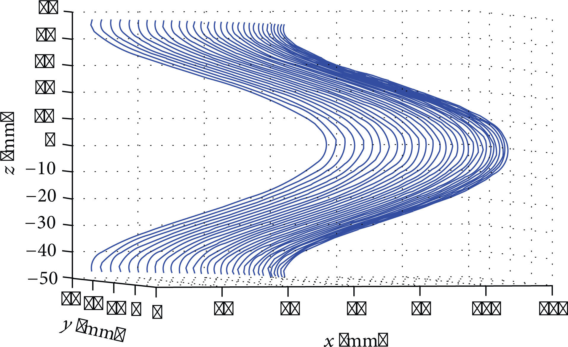
Comparison of the axial curve and the theoretical curve.
The results indicate that the processing error range of the end face of double-helix screw is (−0.005, +0.003) and the processing error range of the axial curve is (−0.007, +0.005). The design allowing error range of double-helix screw is (−0.02, +0.02). It is visible that the process double-helix screw meets the requirements of design, and the profile equation of formed milling cutter is correct.
5. Conclusions
According to the shape and characteristic parameters of the double-helix screw, the helicoids equation and the axial curve equation of double-helix screw were established, which laid the foundation for the profile equation calculation of corresponding formed milling cutter. Using the minimum value method, the contact line equation between formed milling cutter and double-helix screw was established. And the tooth back curve equation was established based on spiral of Archimedes. On this basis, the profile equation of formed milling cutter with constant back angle was got. Based on this mathematical model, the forming milling cutter of double-helix screw was designed and tested by machining. The results showed that the formed milling cutter manufactured in this modeling method can meet the design and the accuracy requirements. The cutter edge of formed milling cutter could keep a good condition after being resharpened; therefore the machining accuracy of the double-helix screw was not affected. The modeling method in this paper is an effective design method to get the profile of formed milling cutter for double-helix screw, and it can be applied to design of forming milling cutter for other helicoids.
Footnotes
Acknowledgments
This work was financed by the National Natural Science Foundation of China (no. 51275014) and National Science and Technology Major Project of China (no. 2013ZX04011-013).