
Abstract
The two- and three-noded spatially coupled thin-walled finite curved beam elements are presented on the basis of assumed strain fields. These elements consider the extensional/inextensional conditions along the centroid axis of curved beam. For curved beams with the extensional condition, the two-noded element is formulated from constant strain and linear curvature fields. And the strain is assumed as linear filed and curvatures are assumed to be third-order ones for the three-noded element. In addition the normal stress at an arbitrary point of symmetric and non-symmetric cross-sections is explicitly evaluated since strain and curvature functions are assumed independently. In order to illustrate the accuracy and the practical usefulness of the present assumed strain curved beam elements, the displacements and the normal stresses of curved beams are evaluated and compared with the previously published results and the solutions by the shell elements from SAP 2000. The emphasis is given in investigating the influence of inextensibility along the beam axis on the coupled behavior of curved beam with respect to the values of boundary condition, subtended angle, and slenderness ratio.
1. Introduction
Curved beam structures have been used in many civil, mechanical, and aerospace engineering applications such as curved wire, curved girder bridges, turbomachinery blade, tire dynamic, and stiffeners in aircraft structures. It can also be used as a simplified model of a shell structure. Investigation into the behavior of thin-walled curved members with open and closed cross-sections has been carried out extensively since the early works of Vlasov [1].
Up to the present, in order to obtain the values of deflections and stresses of curved beams, various analyses techniques have been developed. The energy methods like Castigliano's theorem [2] can be used but this method is only useful in solving simple and decoupled problems and the formulation has to be done separately for each problem. Also the Rayleigh-Ritz method may be applied to evaluate solutions for the curved beam. But the accuracy of the results obtained by this method depends on the chosen displacement functions and a large number of terms have to be used in the displacement functions to get the good results for complicated problems. Moreover, this method has to be formulated separately for each problem since the chosen displacement functions depend on the boundary conditions of curved beam. Thus for the analysis of curved beams, the numerical methods are resorted to the finite element method being the mostly widely used because of its versatility and applicability.
Intensive research works have been made for the improvement of the finite curved beam elements to obtain the acceptable results. Kim and Park [3] and Lee and Kim [4] proposed two-noded hybrid-mixed isotropic and anisotropic curved beam elements, respectively, with internal nodeless degrees and consistent stress parameters based on the Hellinger-Reissner variational principle. Raveendranath et al. [5] developed two-noded curved beam elements, for which a cubic polynomial field was assumed a priori and the polynomial interpolations for the axial displacement and the twisting angle were derived employing force-moment and moment-shear equilibrium equations. Litewka and Rakowski [6] derived the plane two-noded curved beam finite element with six DOF. Unlike the ones commonly used in the FEM analysis, the functions suggested by them have coefficients dependent on the geometrical and physical properties of the element. Friedman and Kosmatka [7] developed the locking-free two-noded (three DOF per node) curved beam element based on the shape functions which satisfy the element equilibrium equations. Also a highly accurate hybrid-mixed C o curved beam element with nodeless degrees of freedom was developed by J. G. Kim and Y. Y. Kim [8]. They examined the role of the nodeless degrees of freedom and the effect of the field consistency. Prathap and Babu [9] and Babu and Prathap [10] derived a three-noded curved beam element based on the independent isoparametric interpolation and field-consistency approach which identifies the spurious constraints of the inconsistent strain field and drops them in advance. This field consistency approach ensured a variationally correct and orthogonally consistent strain field. But this method reduced the order of strain interpolation and suffered from the membrane locking with increase in R/h ratio due to the inconsistency of membrane strain and from the lower convergence rate. Also Prathap and Shashirekha [11] reworked the classical C-L element formulating it in a variationally correct manner by the method of functional reconstitution. However, most of these studies have been restricted to the analysis for only in-plane behavior of curved beam.
On the other hand, a few researchers have been interested in development of the efficient curved beam element for the three-dimensional problems. Yu et al. [12] presented a procedure for analyzing naturally curved and twisted beams under complicated loads, with special attention devoted to the solving process of governing equations which take into account the effects of torsion-related warping. Petrov and Géradin [13, 14] proposed a geometrically exact and consistently finite element theory for curved twisted beams. Sengupta and Dasgupta [15] presented a five-noded horizontally curved beam element having consistent cross-sectional shear centre and centroid and the transverse displacement are interpolated by a set of fourth-degree Lagrangian polynomials while the rotation of longitudinal axis and the twisting angle are described by another set of third-degree polynomials. Fu and Hsu [16] developed a more exact horizontally curved beam finite element in a cylindrical coordinate system. They used a variational method to formulate the stiffness matrix in an explicit form. Also a simple two-noded finite element model was developed by Gendy and Saleeb [17] for the thin-walled curved beams with nonsymmetric cross-section. But in the evaluation of the stress at an arbitrary point of cross-section of curved beam, these studies may lead to more erroneous results since the strain expressions contain the derivatives of second order of the displacement components.
The existing literature reveals that even though a significant amount of research has been conducted on the development of curved beam element for the static analysis, to the author's knowledge, there has been no study in the literature that has reported on the axially-flexurally-torsionally coupled thin-walled curved beam with nonsymmetric cross-section based on the assumed strain fields. Also investigation for the influence of inextensibility along the beam axis on the coupled behavior of curved beam with respect to the boundary condition, the subtended angle, and the slenderness ratio is insufficient.
The primary purpose of this study is to develop the efficient and membrane locking-free curved beam element based on the assumed strain fields. The element developed by this study considers the extensional/inextensional conditions along the centroid axis of beam. Under the extensional condition, the two-noded element is derived from constant strain and linear curvature fields and the three-noded one is derived from the linear strain and third-order curvature fields. Since strain and curvature functions are assumed independently, the beam elements developed by this study are free from the locking phenomenon and especially give accurate results in evaluating the normal stresses at an arbitrary point of cross-sections of beam. In numerical examples, the displacements and the normal stresses of beams with symmetric and nonsymmetric cross-sections are evaluated and compared with the previously published results and the solutions obtained from SAP 2000. Particularly the influence of the inextensionality along the axis of beam on the coupled behavior of curved beam is investigated.
2. Derivation of Force-Displacement Relations
For the derivation of force-displacement relations of the thin-walled curved beam, in this study, the following assumptions are adopted.
The effects of shear deformations due to the flexure and the torsion are negligible.
The thin-walled curved beam is linearly elastic and prismatic.
The contour of a cross-section does not deform in its plane so that there is no distortion.
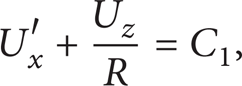
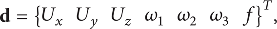
Figure 1 shows the coordinate system of thin-walled curved beam. U x , U y , U z and ω1, ω2, ω3 are the rigid body translations and the rotations of the cross-section with respect to x1, x2, and x3 axes, respectively. f is the warping parameter denoting the gradient of the twisting angle θ(= ω1). Under the assumption of the negligible shear deformation, the parameters ω2, ω3, and f and the axial parameter g can be related with respect to rigid body translations and a twisting angle by Frenet's formula [19] as follows:
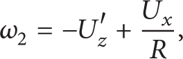
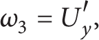


where the superscript “prime” and R indicate the derivative with respect to x1 and the radius of curvature in the x1 – x3 plane shown in Figure 1, respectively. Assuming that the cross-section is rigid in its own plane, the total displacement field can be written as follows:

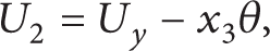
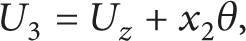
where ϕ is the normalized warping function defined at the centroid. Defining ϕ s as the warping function at the shear center and considering the general thin-walled beam theory, the following relationship between ϕ and ϕ s is obtained:
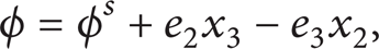
where (e2, e3) denotes the position of the shear center. In addition to displacement parameters, the stress resultants in Figure 1 are defined by


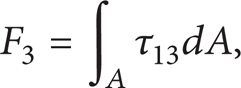


where A is the area of cross-section; τ11 and τ12, τ13 are the normal and shear stresses acting at the centroid; F1 is the axial force; F2 and F3 are the shear forces with respect to x2 and x3 axes, respectively; M1 is the twisting moment with respect to the centroid axis; M2 and M3 are the bending moments with respect to x2 and x3 axes, respectively; Mϕ is the bimoment about the x1 axis. Also the St. Venant torsional moment Mst is expressed as follows:

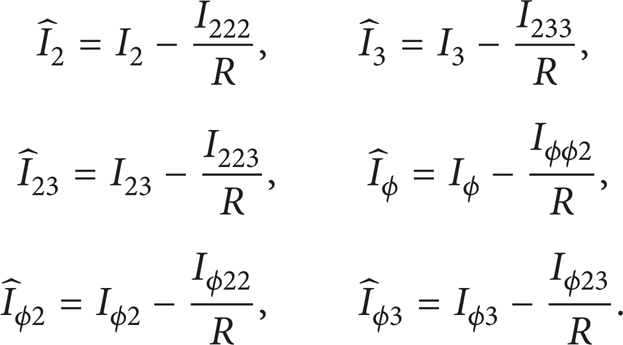
where G and J are the shear modulus and the torsional constant, respectively. For later use, the sectional properties are defined by
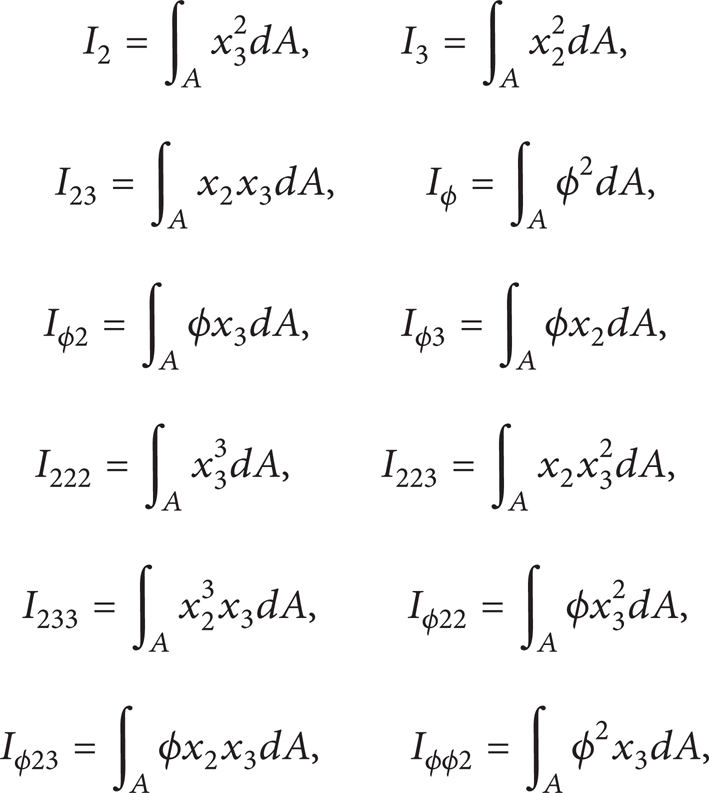
where I2, I3, I23, and Iϕ are the second moment of inertia about x2 and x3 axes, the product moment of inertia, and the warping moment of inertia, respectively; Iϕ2 (= I2e2) and Iϕ3 (= – I3e3) are the product moments of inertia due to the normalized warping; I ijk (i, j, k = ϕ, 2, 3) are the third moments of inertia.

Coordinate system of thin-walled curved beam.
Now, to derive force-displacement relations due to the normal stress, the normal strain-displacement relation may be expressed as follows:

Substituting (7) into (4a), (4e), (4f), and (4g) and considering (5), the following force-displacement relations are obtained:
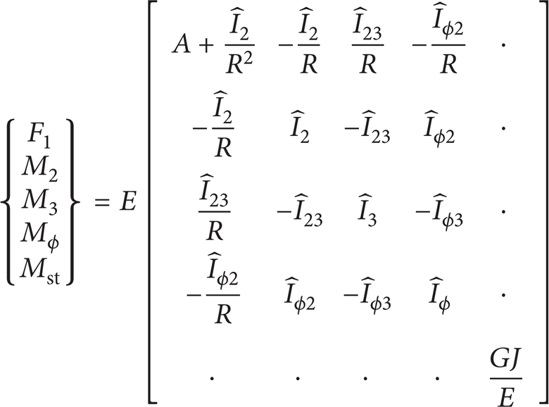
or

where
In the derivation of (8), the following approximation is used in the expression of the linear normal strain in (7):

3. Evaluation of Stiffness Matrices
3.1. Stiffness Matrix of Curved Beam Considering Extensional Condition: Case 1
To derive the stiffness matrices of the two- and three-noded thin-walled curved beams considering the extensional condition, the following generalized strain vector is considered from (8):

where the first term in the brace is the normal strain; the second and third terms are bending curvatures, respectively; the fourth and final ones are the warping curvature and the torsional shear strain associated with the St. Venant torsion, respectively.
The two-noded element is constructed by assuming the strain component to be constant and the curvature ones to be linear as follows:


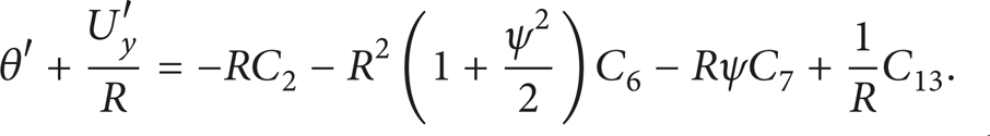
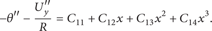
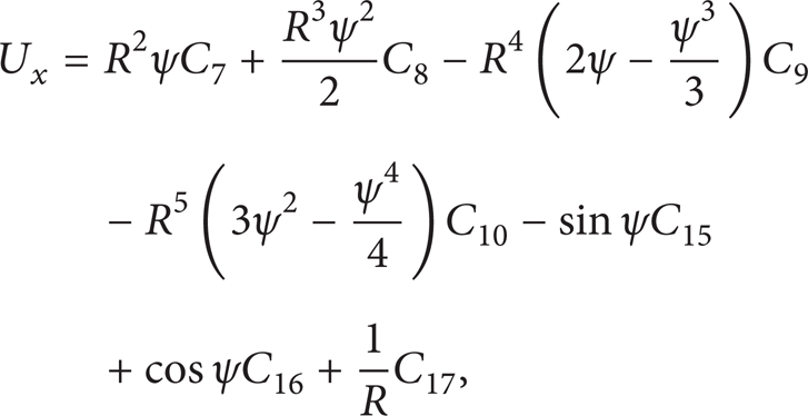
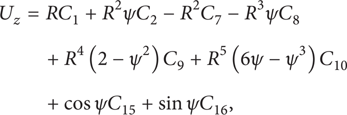
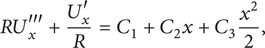
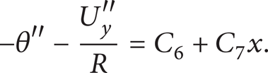
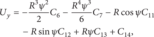
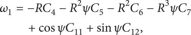
From (1a)–(1c) and (13a)–(13d), we can obtain the general solutions of seven element displacement functions as follows:
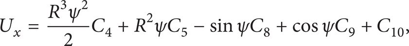


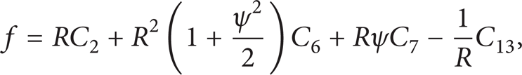
where ψ denotes x/R. From (14b) and (14d), the torsional shear strain associated with the St. Venant torsion is as follows:
Equations (14a)–(14g) can be expressed in matrix form as

where Φ is the general solution matrix of the seven differential equations in a two-noded beam element and

For the three-noded strain element, the strain and curvatures are assumed to be the linear field and the third-order ones, respectively, as follows:


By employing the same procedure as mentioned above, the general solutions of displacement functions are obtained as follows:


and the torsional shear strain can be obtained from (19b) and (19d) as follows:

Equations (19a)–(19g) can be expressed in matrix form and

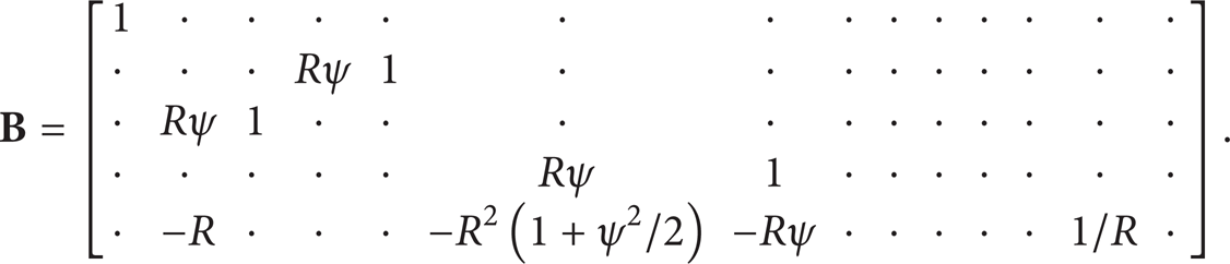
In case of two-noded curved beam element, from (13a)–(13d) and (15), the generalized strain vector

where
For three-noded element,
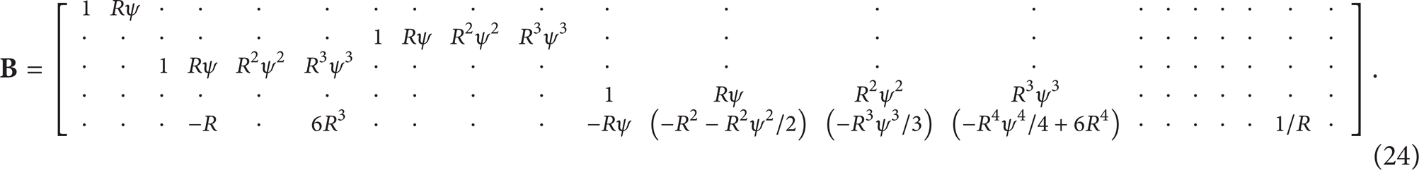
The generalized displacement vector

where


The subscripts mean the nodal point of each element.
Now, the stiffness matrix is derived from the total potential energy theorem and the total potential energy of the curved beam element is express as follows:

where
Finally, by substituting (9), (22), and (25) into (27) and taking the first variation of (27) with respect to Δ, the element equilibrium equation in the local curvilinear coordinate system is obtained as follows:
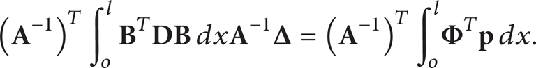
Thus, we can get the element stiffness matrix in the local curvilinear coordinate system as follows:

In order to describe the global behavior of curved beam, it is necessary to define the three sets of coordinate systems: the local curvilinear coordinate system, the local Cartesian coordinate system, and the global Cartesian coordinate system. The first is the transformation of the element matrix from the local running curvilinear coordinate system to the local Cartesian coordinate system. The second one completes the transformation of the element matrix from the local Cartesian coordinate system to the global Cartesian coordinate system. Details for constructing the transformation matrices were given by Choit and Lim [20].
3.2. Stiffness Matrix of Curved Beam Considering Inextensional Condition: Case 2
In this Section, a kinematic constraint is introduced in order to investigate the application of inextensibility along the axis of curved beam as follows:

For two-noded element, (13b)–(13d) can be expressed as the following equations from (30):

The general solutions of seven displacement functions are derived as follows:


Also the expression for the torsional shear strain is as follows:
For the three-noded strain element, the strain and curvature expressions in (18a)–(18d) are simplified to


By solving above three differential equations, the general solutions, for three-noded element, are as follows:


and the torsional shear strain is

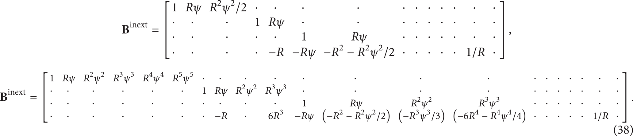
For two- and three-noded strain curved beams considering inextensional condition, the generalized strain vector
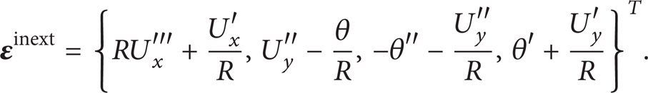
Also the assumed strain function matrices in (23) and (24) can be expressed as follows:
Finally, by referring to (29), the element stiffness matrix of inextensional curved beam is as follows:

where

4. Evaluation of Normal Stress at an Arbitrary Point of Cross-Section
Using stiffness matrices evaluated in previous Section, the displacement vector
For two-noded curved beam considering the extensional condition, the normal strain is expressed from (13a)–(13d) as follows:

and for three-noded element considering the extensional one, e11 is

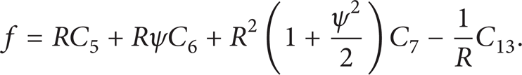
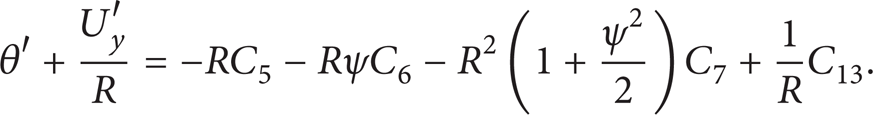
In case of neglecting the extensional condition, for two- and three-noded curved beams, e11inext are expressed from (31a)–(31c) and (34a)–(34c), respectively, as follows:

Finally, the normal stress at an arbitrary point (x2, x3) of the thin-walled cross-section of curved beam subjected to the external forces can be evaluated using Hooke's law. It should be noted that the present normal stress is evaluated explicitly and effectively from the generalized displacement vector since strain and curvature functions are assumed independently, whereas finite curved beam elements using classical interpolation polynomials, though results for such conditions are not presented in this study, may lead to more erroneous stress results at an arbitrary point of the cross-section due to the derivatives of second- or third-order of the displacement components.
5. Numerical Examples
The performance of the two different assumed strain curved beam elements suggested in this study has been studied. For this, numerical solutions for the elastic analysis of thin-walled curved beams with double-, mono-, and nonsymmetric cross-sections are presented and compared with the results from available references as well as the finite shell element analysis results using SAP 2000 [18]. The entire length of the curved beam in subsequent examples is modeled by using 10 two-noded beam elements and 4 three-noded ones based on the convergence study.
5.1. Cantilevered Curved Beam with Monosymmetric Cross-Section
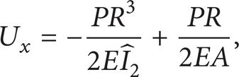
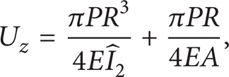
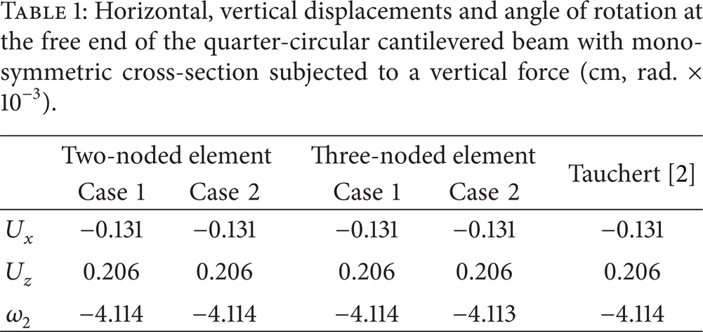
Figure 2 shows the quarter-circular cantilevered beam with monosymmetric cross-section subjected to a vertical force 10 N acting at the centroid of free end and its material and sectional properties. The length of beam is 100 cm. Horizontal and vertical displacements and angle of rotation at free end of beam obtained from 10 two-noded strain elements and 4 three-noded ones are presented and compared with the analytical solutions from the Castigliano's energy theorem [2] in Table 1. Here expressions for displacements and rotation at free end of the quarter-circular cantilevered curved beam subjected to a vertical force P are given by

Horizontal, vertical displacements and angle of rotation at the free end of the quarter-circular cantilevered beam with mono-symmetric cross-section subjected to a vertical force (cm, rad. × 10−3).
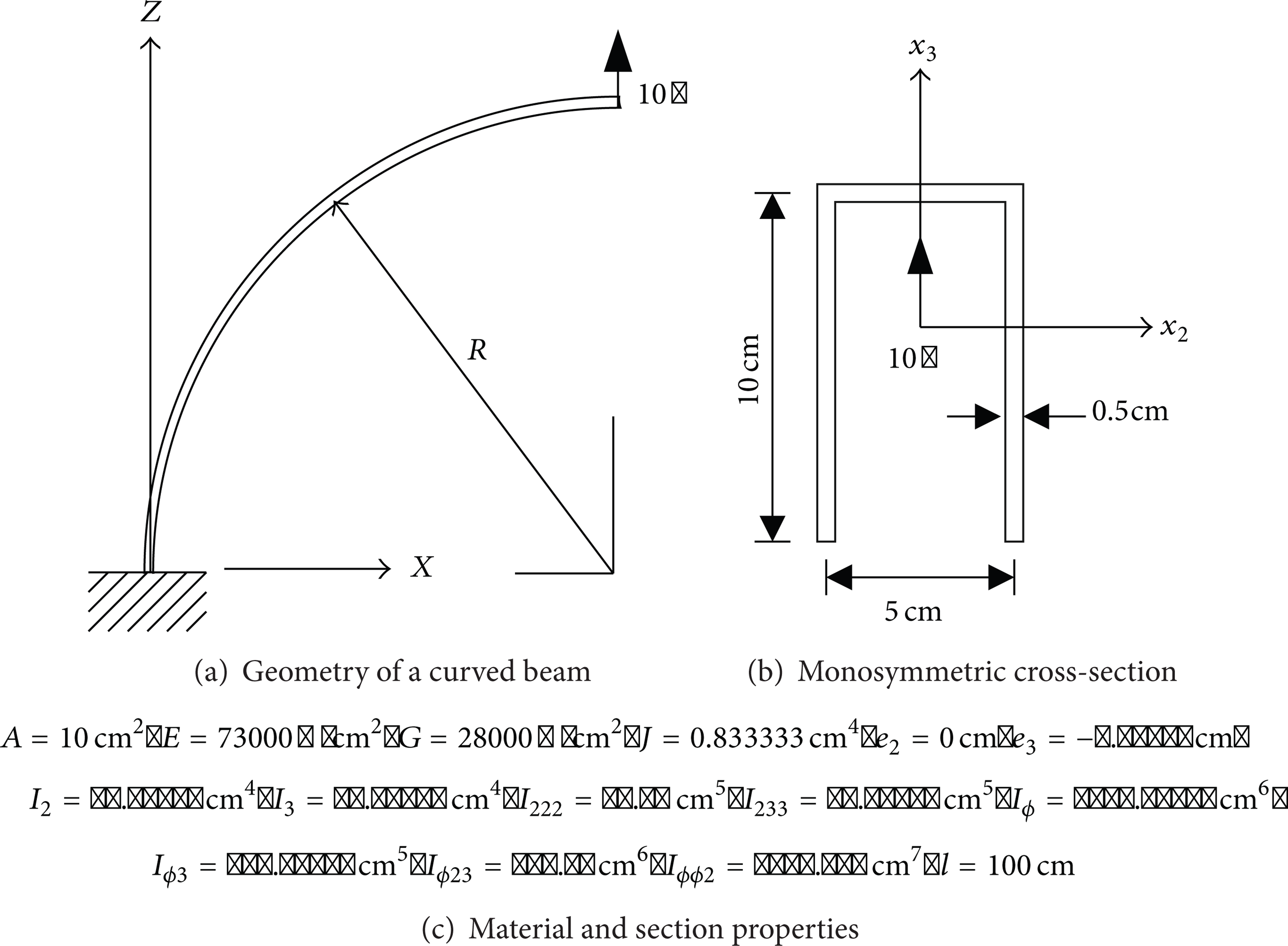
Quarter-circular cantilevered beam with monosymmetric cross-section.
It can be found from Table 1 that the present results are in excellent agreement with the analytical solutions and the difference of values between Case 1 and Case 2 is negligible. Figures 3 and 4 show the convergence trends of normalized displacements and rotation at the loading point of the two-noded strain element under Case 1 and Case 2, respectively, where displacements and rotation are normalized with respect to the analytical solution. Also results of the three-noded strain element for the normalized displacements and rotation are depicted in Figure 5 where values from Case 1 are identical to those from Case 2. From Figures 3 to 5, it can be found that the convergence speeds of both two- and three-noded strain elements are very high. By comparing Figure 3 with Figure 4, it can be observed that the convergence speeds of the two-noded element under the inextensional condition are much higher than those under the extensional one. This is due to the fact that the higher-order displacement interpolation functions can improve the convergence speed significantly.

Convergence of normalized displacements and rotation at the free end of the two-noded cantilevered beam under the extensional condition.

Convergence of normalized displacements and rotation at the free end of the two-noded cantilevered beam under the inextensional condition.

Convergence of normalized displacements and rotation at the free end of the three-noded cantilevered beam under the extensional and inextensional conditions.
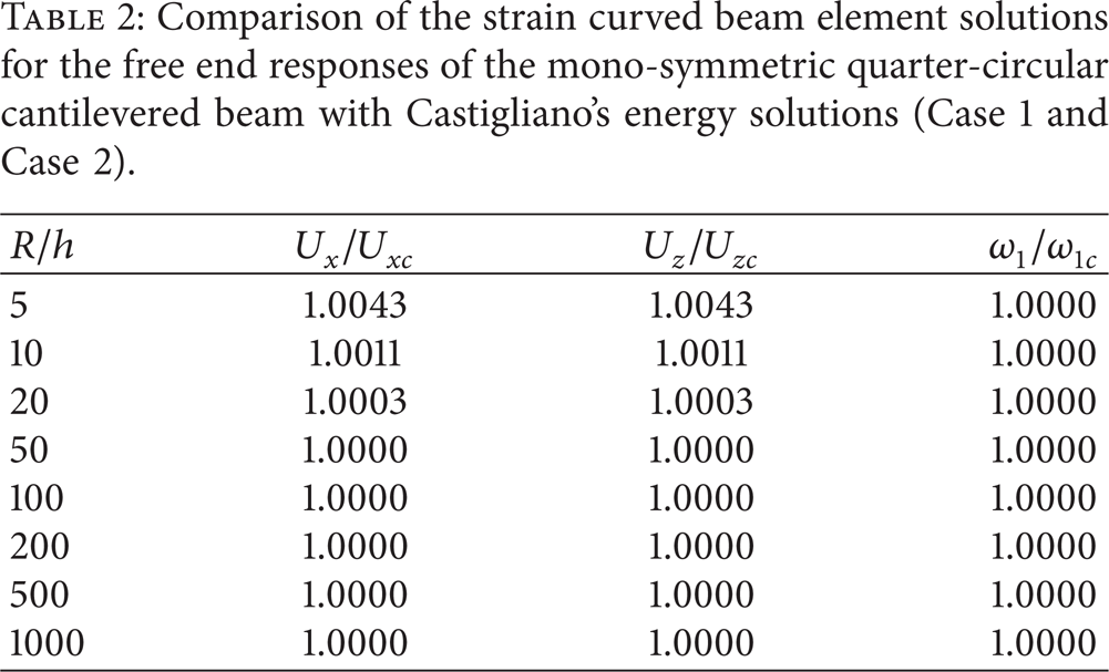
To test the presence of any membrane locking, the curved beam is analyzed for various aspect ratios R/h in which h means the height of cross-section. The normalized results of the two-noded strain element with the Castigliano's energy solutions are presented in Table 2 with increase in R/h. Here the difference of results between Case 1 and Case 2 is negligible. As shown in Table 2, in the thinner regimes, the present element smoothly yields the analytical solutions without exhibiting any locking.
Comparison of the strain curved beam element solutions for the free end responses of the mono-symmetric quarter-circular cantilevered beam with Castigliano's energy solutions (Case 1 and Case 2).
5.2. Cantilevered Curved Beam with Double-Symmetric Cross-Section
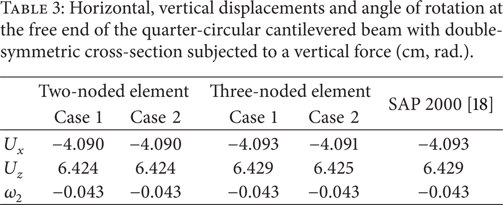
The in-plane and out-of-plane decoupled behavior of cantilevered curved beam with double-symmetric cross-section subjected to a vertical force and a torsional moment at the centroid of free end is considered. The geometry and the cross-section of curved beam and its material and sectional properties are given in Figure 6. For curved beam subjected to a vertical force 10 N acting at the centroid of free end, the horizontal and vertical displacements and the angle of rotation at the loading point are presented in Table 3 and compared with the results by shell elements of SAP 2000. For SAP 2000 calculation, a total of 4320 four-noded shell elements are used to obtain the results. Also in Table 4, the out-of-plane responses of free end of beam subjected to a torsional moment −10 Ncm by this study and the solutions from SAP 2000 are presented together. It can be found from Tables 3 and 4 that the solutions obtained from both two- and three-noded strain beam elements considering or neglecting the extensional condition are greatly in agreement with those by shell elements and the maximum of differences is 0.7% for the flexural rotation ω2 and 1.58% for the lateral displacement U y .
Horizontal, vertical displacements and angle of rotation at the free end of the quarter-circular cantilevered beam with double-symmetric cross-section subjected to a vertical force (cm, rad.).
Lateral displacement and angles of twist and rotation at the free end of the quarter-circular cantilevered beam with double-symmetric cross-section subjected to a torsional moment (cm, rad.).


Quarter-circular cantilevered beam with double-symmetric cross-section.
To show the practical usefulness of the proposed numerical method, the normal stresses of cross-section at midspan of curved beams subjected to a vertical force and a torsional moment are presented in Tables 5 and 6, respectively, and compared with the results from shell elements. From Tables 5 and 6, it can be observed that the results obtained from present elements are in excellent agreement with the SAP 2000′s solutions for points under consideration within a maximum difference of 0.87% and 1.52% at the bottom flange for a vertical force and a torsional moment, respectively.
Normal stresses at mid span of the quarter-circular cantilevered beam with double-symmetric cross-section subjected to a vertical force (N/cm2).

Normal stresses at mid span of the quarter-circular cantilevered beam with double-symmetric cross-section subjected to a torsional moment (N/cm2).

5.3. Curved Beam with Nonsymmetric Cross-Section
In our final examples, we study the axially flexurally torsionally coupled behavior of curved beam with nonsymmetric cross-sections. First, the quarter-circular cantilevered curved beam, as shown in Figure 7, subjected to a vertical force 100 N at the centroid of free end is considered. The beam length is 100 cm and the material and sectional properties are given in Figure 7 (b). Tables 7 and 8 give comparisons of solutions using two- and three-noded strain elements with results using 1440 shell elements of SAP 2000. It is observed from Tables 7 and 8 that an excellent agreement between results from this study and those from the shell element analysis is evident. For calculation of twisting angle ω1 in Table 7 and the normal stress at point ④ in Table 8, the maximum difference between this study and the shell element results is 3.69% and 2.38%, respectively. This discrepancy may occur due to the neglect of the local deformation effect such as a distortional deformation. Moreover, the effect of inextensibility of the curved beam axis is not significant.
Responses at the free end of the quarter-circular cantilevered beam with non-symmetric cross-section subjected to a vertical force (cm, rad. × 10−2).

Normal stresses at mid-section of the quarter-circular cantilevered beam with non-symmetric cross-section subjected to a vertical force (N/cm2).


Quarter-circular cantilevered beam with nonsymmetric cross-section.
Next, Figure 8 shows the curved girder with nonsymmetric L-shaped cross-section. The girder is clamped at two ends and subjected to an out-of-plane lateral force 4.45 kN (1000 lb) at midspan. The lateral displacement U y at the corner of the L-shaped cross-section along the curved girder by present method is depicted in Figure 9. For comparison, by considering the symmetry, the results obtained from 8 HMC2 curved beam elements by Gendy and Saleeb [17], based on mixed variational formulation and 24 quadrilateral shell elements developed by Saleeb et al. [21], are presented together. From Figure 9, it can be found that results obtained from Case 1 are in good agreement with those from HMC2 curved beam elements and shell elements. However it can also be observed that the inextensional condition makes the structure stiff for clamped boundary conditions.

Clamped curved beam with L-shaped cross-section.

Lateral displacement at the corner of clamped curved beam with L-shaped cross-section.
To investigate the influence of inextensible condition on the coupled behavior of curved beam, the curved girder subjected to a vertical force −100 N at midspan, as shown in Figure 10, is considered. The length of beam is 160 cm and the material and sectional properties of nonsymmetric cross-section are adopted in Figure 7. Also the boundary conditions under consideration in this study are as follows (i.e., clamped-free (C-F), simple-simple (S-S), clamped-simple (C-S), and clamped-clamped (C-C) boundary conditions, resp.). First, as the beam length keeps constant but the subtended angle β varies, the ratios of lateral, vertical displacements and twisting angle at midspan of beam from Case 1 to those from Case 2 are plotted in Figures 11, 12, and 13, respectively. From Figures 11 to 13, it is found that the difference of displacements and twisting angle between Case 1 and Case 2 is significant when the curved beam has small subtended angle and the end condition of beam is restrained. It can also be observed that the coupled lateral displacement and the twisting angle as well as the vertical displacement which are evaluated by Case 1 converge to those by Case 2 as the subtended angle increases. Its convergence speed becomes high as the end condition is less restrained. Figures 14, 15, and 16 show the responses at midspan of curved beam from Case 1 and Case 2 as the subtended angle β is taken to be 90° but the length increases. It is seen from Figures 14 to 16 that the coupled responses by Case 1 converge to those by Case 2 with increase in the slenderness ratio. The trend of convergence speed with respect to boundary conditions is found to be similar to the previous problem.

Curved beam subjected to a vertical force at midspan.

Influence of the inextensional condition on the lateral displacement at midspan of nonsymmetric curved beam with respect to subtended angle.

Influence of the inextensional condition on the vertical displacement at midspan of nonsymmetric curved beam with respect to subtended angle.

Influence of the inextensional condition on the twisting angle at midspan of nonsymmetric curved beam with respect to subtended angle.

Influence of the inextensional condition on the lateral displacement at midspan of nonsymmetric curved beam with respect to slenderness ratio.

Influence of the inextensional condition on the vertical displacement at midspan of nonsymmetric curved beam with respect to slenderness ratio.

Influence of the inextensional condition on the twisting angle at midspan of nonsymmetric curved beam with respect to slenderness ratio.
6. Conclusions
In order to perform the spatially coupled analysis of thin-walled curved beam with nonsymmetric cross-section, the simple and efficient two- and three-noded curved beam elements based on the assumed strain fields are developed. This study considers the extensional condition and the inextensional one along the beam axis. Moreover the influence of the inextensibility on the coupled behavior of curved beam is studied parametrically.
Through the numerical examples, it turns out that the decoupled and coupled responses and the normal stresses at an arbitrary point of double-, mono-, and nonsymmetric cross-sections of curved beam by this study are in good agreement with the analytical solutions and the finite element results using the curved beam elements as well as the shell elements. And the three-noded strain element appears to be more effective than the two-noded element. It is demonstrated that for cantilevered curved beam, the effect of inextensibility of beam axis is not significant. Whereas it makes the beam structure stiff as the end condition of beam becomes restrained. Also the coupled responses applying the extensional condition converge to those applying the inextensional one as the subtended angle and the length of beam increase.
It is judged that the present strain curved beam elements reduce the number of element significantly for analysis. Since the strain and curvature functions are assumed independently, these elements are free from any membrane locking in the thinner regimes and especially give accurate results in evaluation of normal stress at an arbitrary point of cross-section of curved beam.
Footnotes
Acknowledgment
This work was supported by the University of Incheon (International Cooperative) Research Grant in 2013.