
Abstract
To maintain safe operation of the tower crane, it is important to monitor the activities of the hook system. Visual monitoring and image recognition are the optimum methods for crane hook tracking and precision hoisting. High real-time performance and low computation requirements are required for tower crane hook capturing and tracking system which is implemented on the embedded Advanced RISC Machines (ARM) processor or Microcontrol Unit (MCU). Using the lift rope of a tower crane as the target object, a new high-performance hook tracking method suitble for ARM processor or MCU applications is presented. The features of the lifting process are analyzed, and an improved progressive probabilistic Hough transform (IPPHT) algorithm is proposed which canreduce capturing time by up to 80%. Combining color histogram with a binary search algorithm, an adaptive zooming method for precise hoisting is presented. Using this method the optimum zoom scale can be achieved within a few iterations.
1. Introduction
Tower cranes are important hoisting machinery widely used for construction. Advancing toward large-scale, high-speed, and automated operation leads to dramatic increases in losses caused by accidents that increase dramatically in the tower crane industry. Although many safe standards have been formulated, the recent spate of tower crane accidents has casted a spotlight on the need for tower crane safety [1]. Load hoisting is the most critical task performed by tower cranes, determining project quality, and it is during this task that accidents occur. Automatic monitoring and controlling of hoisting cannot only reduce the severity and numbers of tower crane accidents but also improve operation quality and efficiency.
Working safety in tower crane operation has recently been highlighted, and many types of safety devices have been designed. These devices can be divided into two classes: devices used to protect equipment from overloading [2, 3] and devices used to keep people away from hazard zone [4, 5]. Loads are often lifted over building constructions, thus resulting in blind zone for operators. Blind lifting is one of the main practices that adversely affect tower crane safety [6]. Hoisting process monitoring is a useful way to avoid blind lifting. However, little information can be provided to monitor the hoisting process using the aforementioned devices fore-mentioned. The hoisting process can be characterized by the motion of crane hooks; thus, capturing and tracking of crane hook motion are feasible methods for hoist-monitoring and evaluation.
Visual monitoring of working activities through the installation of surveillance cameras has become prevalent in the construction industry. A previous study detailed the development of a tower-crane-mounted live video system [7]. On-site testing proved that the system can improve site productivity and safety, but the imagery lacked the visual depth perception rendered by human eyes due to weak capacities for adaptive tracking and zooming in the loads. Visual tracking of a crane jib and trolley was used to monitor tower crane activities [8]. Rather than focusing on detecting a specific load carried by the tower crane, the hoisting activities of the crane were inferred using information gathered from both the crane jib and the trolley in conjunction with the layout plans of the site considered. In another study, a crossmark was labeled on the hook of a truck crane to facilitate recognition by camera, and the hook was tracked using a PID control scheme [9]. The recognition performance was greatly affected by the rotation angle of the hook, and it was determined that the camera should be perpendicular to the crossmark. Continuously adaptive mean shift (Camshift) is an efficient tracking algorithm [10], and an improved Camshift tracking algorithm was proposed for a testing system that performs tower crane automatic tracking and zoom video monitoring [11]. The Camshift algorithm is too complex to implement using an Advanced RISC Machine (ARM) system, which is used in field activity monitoring, thus leading to low real-time performance for hook tracking. To measure the three-dimensional position of a moving crane hook, hook motion is tracked according to the variation in its area using optical flow and orientation code matching [12]. In addition to image processing techniques, virtual visualization and simulation are also often adopted for activity tracking and project management. Activities are reconstructed using a 3D or 4D model of the crane according to real-time monitoring data and building information modeling (BIM) [13–15]. Virtual visualization and simulation are advanced methods used for project management, but their output is too rough for activity tracking and precision hoisting due to a lack of detailed information regarding the activities performed by a crane and the crane's surroundings.
Currently, visual monitoring and image recognition are still the premier methods for crane hook tracking and precision hoisting. High real-time performance and low computation complexity are two key attributes of a practical tracking algorithm used for real-world applications. The controller of the tower crane hook capturing and tracking system is usually ARM-based or MCU-based. However, the operational capabilities of these processors are inferior to those of a personal computer; thus, more efficient algorithms are needed to guarantee high real-time performance. By selecting the lift rope of a tower crane as the captured object, a new highly efficient hook tracking method suited for ARM or MCU applications is presented in this paper. The hoisting features and reasons for selecting the rope as the captured object are analyzed, and an improved progressive probabilistic Hough transform (IPPHT) algorithm is proposed, which reduces the computational time by almost 80%. In this study, an adaptive zooming method for precision hoisting was developed by integrating color histograms with a binary search algorithm. The method was tested, and the results are herein presented.
2. System Architecture and Information Flow
Figure 1 is an illustration of the system architecture designed for the adaptive load capturing and tracking of a tower crane hook. The image information recorded by the camera is converted from analog to digital, and the IPPHT algorithm is then applied to capture the movement of the rope and to track the trajectory of the hook quickly and accurately. A Camshift-based adaptive zooming algorithm integrating color histograms with a binary search algorithm is implemented and executed to provide a detailed observation of hook activities and the surroundings, which is necessary for safe, precision hoisting. The functions of capturing, tracking, and zooming are performed by a pan-tilt camera controlled by the PELCO-Protocol. The capturing and tracking video can be displayed for field monitoring and operation guidance; moreover, the imagery can be transmitted to a remote server for activity monitoring and project management after being compressed. The IPPHT-based capturing and tracking algorithm and adaptive zooming algorithm are the key components of the system, especially when the system is implemented using an ARM9 processor, which demands high computation efficiency. The algorithms are described in Section 3 and Section 4, respectively.
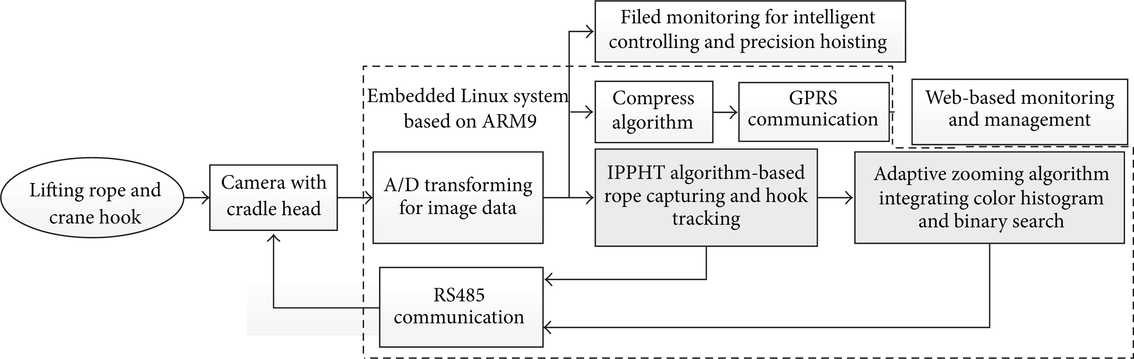
Overall architectures of adaptive load capturing and tracking system.
3. IPPHT-Based Algorithm for Rope Capturing and Hook Tracking
3.1. Analysis of Rope Features during Hoisting
One of the purposes of capturing and tracking hook movements is to maintain a suitable size for the hook and its load in the center of the visual field. There are two factors that make it difficult to select the hook and its load as the objects to be captured and tracked. One is the fact that many shape features generated by buildings are intermingled with images of the hook and its load; the other is the fact that the shape and size of the hook in visual field vary greatly with changes in the rotation and position of the hook when hoisting.
Figures 2 (b) and 2 (d) are images of the rope and hook obtained from the images as shown in Figures 2 (a) and 2 (c), respectively, using the Canny edge detection algorithm. Compared with the hook, the hoisting rope offers some advantages as the object to be captured and tracked. First, the hook is connected to the end of the rope; therefore, the hook position can be indicated using the coordinates of the end point of the rope. Second, the shape of the hoisting rope is linear; thus, the rope is easily recognized and captured compared to the complex shape of the hook. Finally, the rope end only slides vertically to the ground; therefore, it can be conveniently tracked. We observed the following features of the hoisting rope and hook.
The rope is nearly perpendicular to the ground with θ ≤ ± 20°, where θ is the swing angle of the rope.
As illustrated in Figure 2, the rope in the images processed using the Canny edge detection is represented by two parallel edges. However, it may be become a single edge due to the noise generated on one side of the rope when the image is taken from a long distance.
As illustrated in Figure 2 (b), a slight curve sometimes appears in the rope images due to wind effects or the swimming of suspension arm. As a result, the line detection algorithm may fail and many line segments with slopes may be generated.
In addition to the rope, many other line shapes generated by steel structures and buildings are also detected in the images.

Images of rope and hook processed by Canny edge detection algorithm.
3.2. Rope Capturing and Hook Tracking Based on Improved Progressive Probabilistic Hough Transform (IPPHT)
The Hough transform (HT) is a popular and robust method for detecting lines in an image [16]. However, high computational and storage requirements are the drawbacks of the standard Hough transform (SHT) applied for real-time detection. Moreover, this simple transform fails to determine any information regarding the lengths or the start and end points of lines. Therefore, many variations of Hough's original transform have been proposed. The progressive probabilistic Hough transform (PPHT) can minimize the proportion of points that are used in voting when trying to maintain false-negative and false-positive detection rates at the level achieved by SHT [17]; thus, the requirements of computational and storage requirements can be reduced. On the other hand, the output of the PPHT can be denoted by the coordinates of the two end points of a line segment, which makes the transform suited for detecting the lift rope of a tower crane.
Although the computational and storage requirements are reduced, the PPHT is still too complex for the system shown in Figure 1, in which image recognition and tracking are implemented using an ARM-based system. Test reveals that the algorithm will spend 2 s to 3 s to detect image measuring a picture of 160 × 320 pixels using an S3C2440 processor at the basic frequency of 400 MHz. On the other hand, the PPHT is not satisfactory for the detection of a rope with the features mentioned in Section 3.2. Thus, an improved progressive probabilistic Hough transform (IPPHT) is presented for hoist rope detection and hook capture.
3.2.1. Progressive Probabilistic Hough Transform with Angle Constraints
Let (ρ, θ) denote a point in the parameter space and (x, y) denote a point on a straight line in the image space; the parameter ρ represents the distance between the line and the origin, whereas θ is the angle of the vector from the origin to the closest point on the line. The basic mapping relation is expressed as follows [16]:
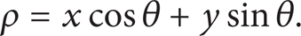
Figure 3 illustrates the mapping relation of the HT for line detection. As shown in Figure 3, θ is also the angle of the line relative to the y-axis. Because the lift rope swings only from −20° to +20°, a constraint of θ ∊ [– 20°, 20°] is applied to (1) for the lift rope detection. Thus, (1) can be expressed as follows:


Mapping relation of HT and the angle of the line relative to the y axis.
Let Nθ denote the number of bins for the angle, and let Nρ denote the number of bins for the distance from the origin. The parameter space is divided into Nρ × Nθ accumulators, which can be represented by the two-dimensional array A[m][n]. a[i][j] is the element of the ith row and the jth column, which is used to store the vote number at the parameter pair (ρ0 + iΔρ, θ0 + jΔθ) and


ρmax is the maximum of ρ. Thus,
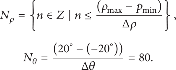
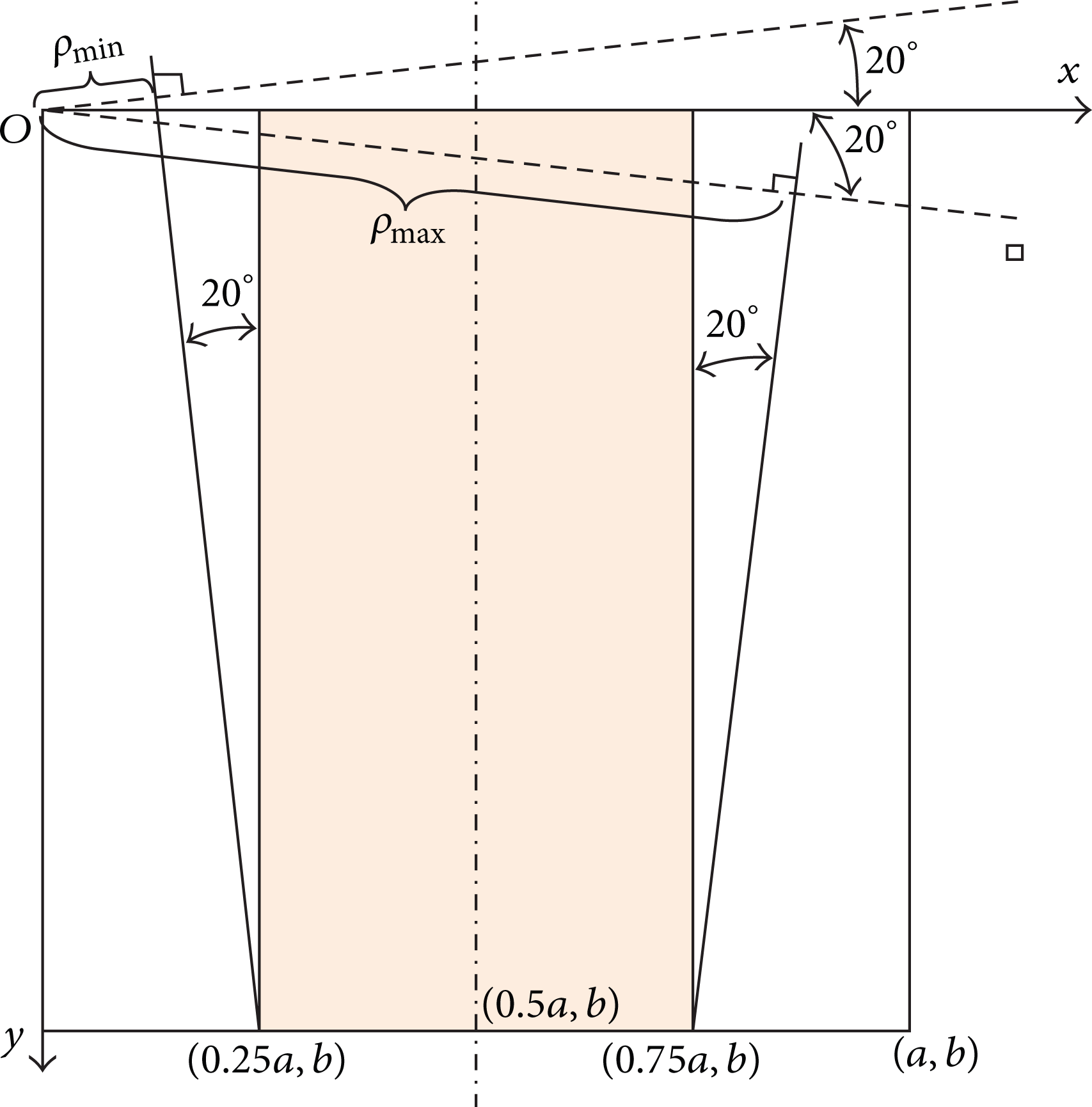
Ranges of ρ.
The PPHT algorithm with angle constraint is improved as follows.
Step 1. Define a subzone as shown in Figure 4 for lift rope detection.
Step 2. Obtain an image with the Canny edge detection algorithm.
Step 3. Check the input image; if it is empty, then terminate.
Step 4. Vote into the accumulator with a single pixel randomly selected from the input image according to (2).
Step 5. Check if the highest peak in the accumulator that was modified by the new pixel is higher than predetermined threshold thr (N). If it is not, then go to Step 4. The threshold thr (N) is determined with a probability estimation which will be described in the next section.
Step 6. Search along a corridor specified by the peak in the accumulator, and find the longest segment that either is continuous or exhibits a gap not exceeding a given threshold. Eliminate noises and amend curves when searching.
Step 7. Remove the pixels in the segment from the input image.
Step 8. Cancel the accumulator votes of all the pixels from the line that have previously voted.
Step 9. If the line segment is longer than the minimum length, add it to the output list.
Step 10. Go to Step 3.
3.2.2. Termination Condition for Voting
In the IPPHT, the termination of voting is based on monitoring the polling process. The criterion is based on a measure of stability of the ranks of the highest peaks [17]. Let C(ρ, θ) denotes the voting number at parameter pair (ρ, θ); thus, C(ρ, θ) is an independent random variable with binomial distribution B(N, p), where N is the number of edge pixels that have voted so far and
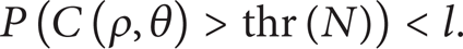
In (5), thr (N) is a threshold that needs to be determined, and l = 5% is a user parameter that indicates the number of false positives.
It has been proved that results identical to those of SHT can be obtained even if only a fraction of input points as low as 2% is used in the voting process of the PPHT [17]. Let N = 50 and
3.2.3. Search Method of Line Segment for Noise Elimination and Curve Amendment
To eliminate edge noises and to amend the curve in the rope image mentioned in Section 3.1, a line segment search method is used. Figure 5 illustrates the search method. The line representing the lift rope in the processed image is nearly parallel to the y-axis, with an angle varying from −20° to 20°. Suppose I(i0, j0) is a point on the line. A line segment perpendicular to the y-axis is selected as the search section. I(i0, j0) is the midpoint of the search section. Define
Then, Ti0, j0 is selected as the condition to determine whether the search should end or continue.

Search method.
If Ti0, j0 = 1, then i0 = i0 + di, j0 = j0 + dj, and the search process continues.
If Ti0, j0 = 0, then the search process ends, and I(i0, j0) is the end point of the line.
In (7), Pi, j is a Boolean variable. Pi, j = 1 indicates that a pixel exists at coordinates (i, j), and Pi, j = 0 indicates that there is no pixel at coordinates (i, j). n is the half width of the banding neighborhood.
The voting rule is modified relative to the rule in the PPHT in order to eliminate the edge noise and to amend the curve in the rope image mentioned in Section 3.1. As illustrated in Figure 5, point I(i0, j0) is the midpoint of the line, and point I′(i′, j′) is a random point in the search section at point I(i0, j0). Moreover,
Define C(ρ, θ) as the voting number at (ρ, θ); the initial value of C(ρ, θ) is C(ρ, θ) = 0. Consider

The new voting rule then is expressed as follows.
If Pi0, j0 = 1, then the operation of C(ρ, θ) = C(ρ, θ) + 1 is executed for all elements in A.
If Pi′, j′ = 1, then the operations of C(ρ, θ) = C(ρ, θ) – 1 are executed for all elements in B, and at the same time the operation of C(ρ, θ) = C(ρ, θ) + 1 is executed for all elements in A.
3.3. Precision and Efficiency of IPPHT Compared to Those in PPHT
Figures 6 (a) and 6 (b) are two edge images processed with the Canny edge detection algorithm for the lift rope of a tower crane. Figures 6 (c) and 6 (d) are the detection results obtained from the images in Figures 6 (a) and 6 (b), respectively, using the PPHT. In Figure 6 (c), the edge of the rope is a nonsingle-pixel edge and is regarded as two parallel lines. In Figure 6 (d), only parts of the rope are detected due to the slight curve of the rope. Figures 6 (e) and 6 (f) are the detection results obtained from the images in Figures 6 (a) and 6 (b), respectively, using the IPPHT. The test conditions used for the PPHT and IPPHT are the same. The width of search section in the IPPHT is 5 pixels. The detection results presented in Figures 6 (e) and 6 (f) are more accurate than those presented in Figures 6 (c) and 6 (d). An added line segment generated by the steel structure is also detected, but it can be excluded by defining a valid image zone. The rope should appear at the center of the image along the x-direction due to the relative position of the camera and the rope; thus, only the line nearest to the center of the image is selected as the rope image. All other lines should be excluded.
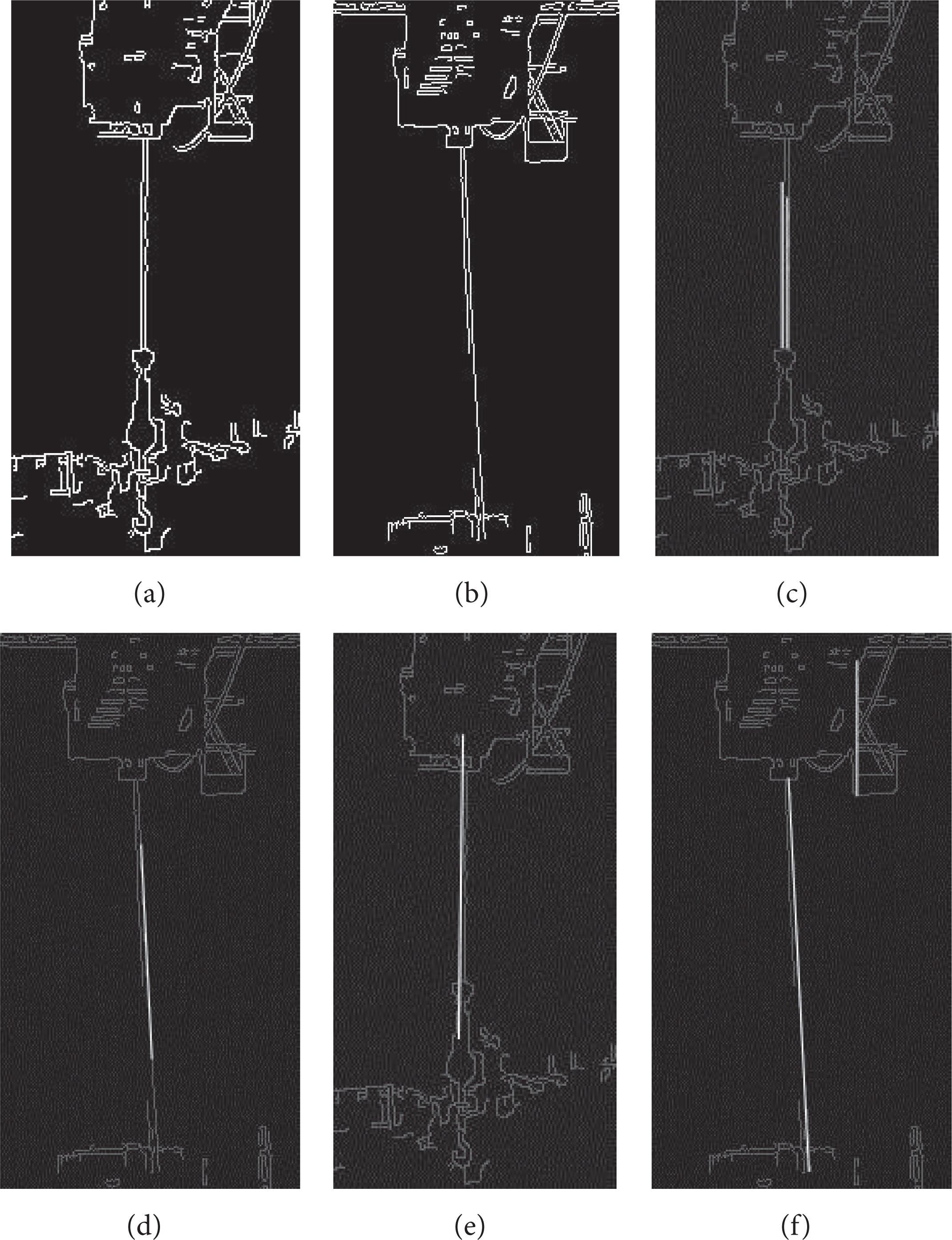
Detection results using both PPHT and IPPHT.
The algorithms were implemented with an S3C2440 processor-based ARM system at 400 MHz using a Linux operation system. The computation times for images shown in Figures 6 (c) and 6 (d) were 2998 ms and 3001 ms, respectively. The computation times for the images shown in Figures 6 (e) and 6 (f) were 417 ms and 617 ms, respectively. Therefore, the IPPHT algorithm is suitable for real-time detection and monitoring.
3.4. Implementation of Hook Autotracking Based on IPPHT
The tracking process of the hook is implemented in the following steps:
detect the rope with the IPPHT;
to search the end point of the line segment downward along the line, take the end point as the starting position of the hook, and then save the coordinates of the end point;
sample the hook position periodically in intervals of 1 s; then, adjust the pitch angle of the camera according to the change in the hook position using PID algorithm.
4. Adaptive Zooming for Precision Hoisting
The size of the hook that appears on the monitor should be adjusted to satisfy the requirement for precision hoisting. Object recognition must be performed before the hook size to be adjusted appears on the monitor. The shape of the hook system is intricate; moreover, its image shape on the monitor varies with the rotation and translation of the hook. Hook systems are often painted with striking colors, typically a combination of yellow and black, black and red, or yellow and red, to provide warning. Therefore, color is a suitable feature for hook system image retrieval. Color histograms have been used extensively for image retrieval and recognition due to their rotation- and translation-invariant properties. To improve the retrieval speed, a hook image zooming algorithm combining color histograms with a binary search was proposed.
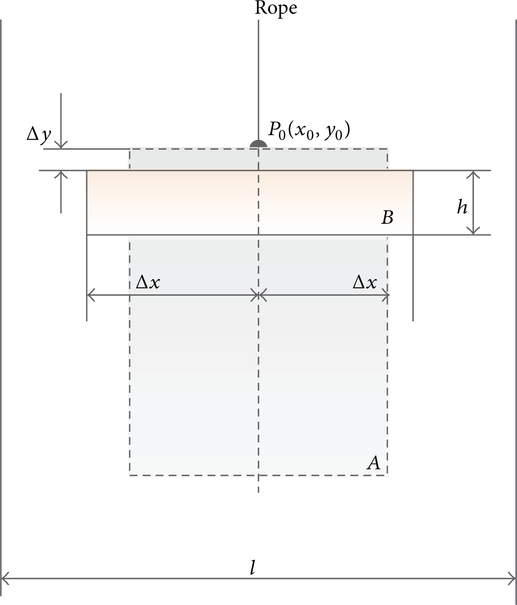
Figure 7 illustrates the color histogram developed using a binary search. P0(x0, y0) is the end point of the lift rope, and A is the hook system image zone. B is a block used to determine the size of the hook system, l = L/4, and L is the width of the vision field. To eliminate the effects of an irregular rope shape, let Δy = 10 pixels and h = 20 pixels.
An illustration of color histogram based-binary search.
Suppose R ij , G ij , and B ij are the R, G, and B component values of pixel point P(i, j) in RGB color space respectively. Define the maximum and minimum component values of R ij , G ij , B ij as M and m [18]:

Define

In (11) H ij is the value of the component H in HSV color space at pixel point P(i, j). H ij is transformed from RGB color space [19]. Consider

Define

In (13),

The color of point P(i, j) is determined as follows:
if a0(i, j) = 1, then the color of point P(i, j) is black;
if a1(i, j) = 1, then the color of point P(i, j) is tangerine;
if a2(i, j) = 1, then the color of point P(i, j) to red;
if a3(i, j) = 1, then the color of point P(i, j) is yellow.
The proportions of black, tangerine, red, and yellow colors in the zone are calculated using (13), and a binary search of the image zone of the hook system is then executed as follows:
if p1 < 0.85, let
if p1 > 0.9, let Δx = 2Δx, and then recalculate p and p1 as indicated in (13);
if 0.85 < p1 < 0.9, then end the search, and take 2Δx as the width of the hook system image.
Once the width of the hook system image in the current vision field is obtained, the camera is zoomed to make sure that 2Δx is one-tenth to one-eighth of the width of the vision field in the monitor. Figure 8 shows an instance of the width of the hook system being zoomed to one-eighth of the vision field, for which only four iterations are executed.

An instance of zooming result.
5. Conclusion
Automatic monitoring and controlling of load hoisting can not only reduce the severity and number of tower crane accidents but also improve operation quality and efficiency of tower crane. Using the lift rope of a tower crane as the object to be captured, an IPPHT-based hook tracking algorithm was proposed and analyzed. The hook can be tracked quickly and accurately. Greatly reducing the computation complexity and storage requirements allows the algorithm to excel in ARM systems, which are widely adopted in the field control and monitoring of tower cranes. The algorithm can reduce the capture time to almost 80% that of the PPHT algorithm. A zooming algorithm in which color histograms are combined with a binary search algorithm was also proposed and analyzed to adjust the hook system to a suitable size on display monitors for precision and safe lifting. Only relevant colors are calculated, and the optimum zooming scale can be achieved in only a few iterations. The validity of the algorithms was tested.
Footnotes
Acknowledgments
This work was supported by the National High Technology Research and Development Program of China (Grant no. 2012AA041804), the National Natural Science Foundation of China (Grant no. 51275290), a Research Project of the State Key Laboratory of Mechanical System and Vibration MSV201206, and a Research Project of Shanghai Science and Technology Committee (11dz1121502).