
Abstract
In the present paper, identification of dynamic sensing characteristics of macrofiber composite (MFC) and polyvinylidene fluoride (PVDF) is carried out via experimental investigation. As a first step, basic characteristics and operating principles of MFC and PVDF are briefly reviewed. Then, a clamped aluminum beam structure is prepared and experimental setup for vibration signal test is established with shaker system. Both MFC and PVDF are attached on the top and bottom surface of the beam structure, respectively, and connected to data acquisition system. In order to verify the operating bandwidth, frequency responses of the smart beam structure are obtained from 0 Hz to 5 kHz under sine sweep excitation. For the identification of dynamic sensing characteristics, experiments for linearity, durability, and robustness are conducted. It is observed that both MFC and PVDF have excellent sensing performance in measuring dynamic response and monitoring structural vibration.
1. Introduction
Smart structure consists of controller, distributed actuators and sensors and has the capability to respond to a change of external and internal environment. Controller (microprocessor) analyzes the response from the sensors and uses control strategies to command the actuators to apply proper control input to minimize system response. In particular the tremendous growth in the use of microprocessor has propelled the demand for the smart sensors and actuators in diverse applications. Many kinds of smart materials, such as piezoelectric materials, shape memory alloys, electrorheological fluids, and magnetorheological fluids, have been considered as actuator and sensor for various applications [1, 2]. Piezoelectric materials are most commonly used as smart materials due to their wide bandwidth, quick response, and low power consumption. Piezoelectric materials produce electric charge or voltage when mechanical forces or strains are applied (direct piezoelectric effect) and conversely make mechanical deformation when an electric field is applied (converse piezoelectric effect). By taking advantage of direct and converse piezoelectric effects, piezoelectric materials can be employed as both sensors and actuators in the development of smart structures. For the last two decades, tremendous research works have been carried out for the effective vibration control of flexible structure with piezoelectric actuators and sensors. Crawley and de Luis provided pioneering work in this area involving the development of the induced strain actuation mechanism [3]. They developed a model of the mechanical coupling of bonded piezoelectric actuators to the dynamics of the structural member. Tzou et al. presented new distributed sensor and actuator design for vibration control of flexible robot arm structures [4]. Hanagud et al. established equation of motion of the cantilever beam with piezoelectric actuators and sensors by using finite element method [5]. Tzou and Tseng developed finite element method with considering distributed piezoelectric materials and investigated dynamic characteristics of plate with piezoelectric actuators and sensors [6]. An experimental model and a finite element simulation were studied and the effectiveness was evaluated. Choi and Hong proposed inertial type piezoelectric mount using piezostack actuator and experimentally evaluated vibration control performance of flexible structure [7]. Zhang et al. developed structural dynamic equations of motion for a 3-PRR parallel manipulator with flexible intermediate links and modal characteristics are experimentally validated [8]. Recently, macrofiber composite (MFC) and polyvinylidene fluoride (PVDF) are widely used as sensor and actuator for the flexible structure since they have great flexibility, low stiffness, and low mass effect. Bailey and Hubbard developed the first smart structure using PVDF [9]. By implementing both constant gain and constant amplitude controllers, they experimentally demonstrated that the PVDF actuator could significantly increase the system damping when the structure was subjected to an initial displacement. Liao et al. numerically evaluated a robust controller for suppressing elastodynamic response of the high speed flexible linkage mechanism with piezoelectric films [10]. Choi and Sohn presented vibration control performance of smart beam, including piezoelectric film actuators, with robust sliding mode control algorithm [11]. Tarazaga et al. investigated the modal characteristics of the space inflatable structure and controlled structural vibration by using PVDF and MFC actuators and sensors [12]. Sohn et al. conducted active vibration control of smart hull structure with surface-bonded MFC actuators and sensors [13, 14]. Kimito and Shimada proposed new multifunctional pressure sensor based on PVDF films [15]. Jia et al. evaluated the performance of PVDF temperature sensor via simulation and experiments [16]. Krishna and Harursampath evaluated MFC sensor performance for a delamination sensor in composite materials [17]. In the case of sensor application of piezoelectric material, the voltage or rate of voltage change and the frequency spectrum of the signal generated by an applied mechanical stress are used. A major advantage of using piezoelectric sensors as opposed to conventional strain gauges is their superior signal-to-noise ratio. Other advantages are their compactness and sensitivity over a large bandwidth and ease of implementation. In general, the key factors for the sensor application of the PVDF and MFC are their sensitivity, bandwidth, linearity, and durability. Typically, it has been reported that the sensitivity of piezofilm and piezoceramics is 10e−4 Volt per strain and the bandwidth is 0.1 GHz [2]. However, the research on the identification of other sensing performances of the MFC and PVDF sensor, such as linearity, repeatability, durability, and robustness, is relatively rare.
Consequently, the main contribution of the present work is to ascertain the sensing performances and dynamic sensing characteristics of the piezoelectric sensors by carrying out a comparative evaluation of MFC and PVDF via experimental investigation. As a first step, characteristics and operating principles of MFC and PVDF are reviewed in brief. MFC and PVDF are attached on the top and bottom surface of an aluminum beam structure, respectively. Then experimental apparatus with clamped aluminum beam structure is prepared and installed to shaker and data acquisition system. In order to verify the operating bandwidth, frequency responses of smart beam structure from 0 Hz to 5 kHz are obtained with sine sweep excitation. For the identification of sensing performance, linearity, durability, and robustness test are carried out. It has been observed that both MFC and PVDF have excellent sensing performance in measuring dynamic response and monitoring structural vibration.
2. Characteristics of MFC and PVDF
2.1. MFC
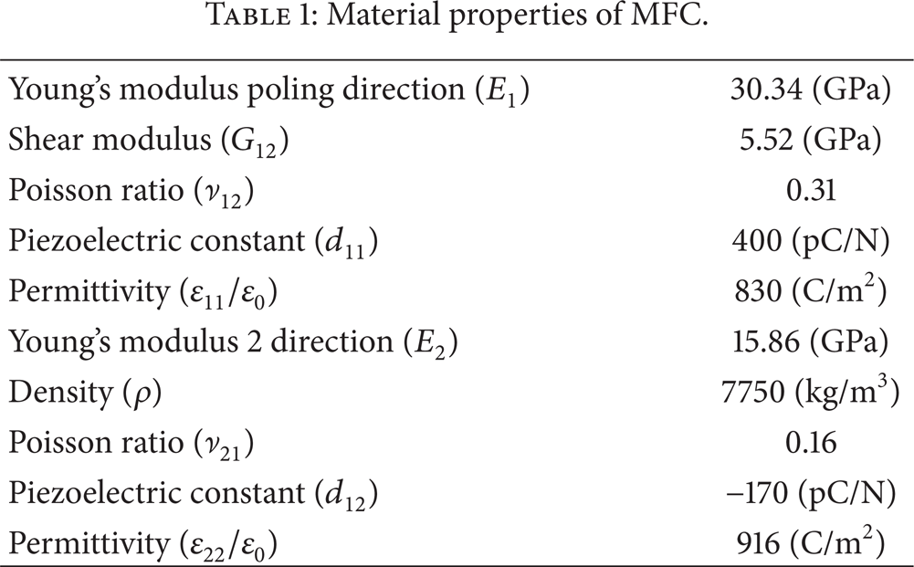
After development of lead zirconate titanate, known as PZT which is an abbreviation of the chemical formula, around 1952, piezoceramic materials have been used extensively in the fields of sensing and actuation. However, these piezoceramic materials have several properties that limit their application in real systems. The brittle nature of the monolithic piezoceramic materials makes them vulnerable to accidental breakage during handling and bonding procedures. In addition, they have very poor ability to apply to curved surfaces and are very dense and stiff causing mass loading and localized stiffness to be a factor when working with very flexible or lightweight structures. To resolve the inadequacy of the monolithic piezoceramic material for many applications, NASA Langley Research Center developed the macrofiber composite (MFC) in 2000. MFC is a composite material consisting of an active piezoceramic fibrous phase embedded in a polymeric matrix phase. Typically when in fiber form crystalline materials have much higher strengths, where the decrease in volume fraction of flaws leads to the increase in specific strength [18]. In addition, the flexibility of the polymer matrix allows the piezoceramic fibers to have greatly increased conformability to curved surfaces and provides a protective shell around the piezoelectric material. This polymer shell allows the piezofiber to withstand impacts and harsh environments far better than monolithic piezoelectric materials. The result of configuring the piezofiber inside a polymer matrix is an actuator that can be incorporated into or bonded to more realistic structures. The three primary components of MFC are active piezoceramic fibers aligned in a unidirectional manner, interdigitated electrodes, and an adhesive polymer matrix. The schematic configuration of MFC is presented in Figure 1. Since fibers are machined from low cost piezoceramic wafer and a computer controlled dicing saw, the fibers of the MFC have a rectangular cross-section. MFC has extreme flexibility, durability, and the advantage of higher electromechanical coupling coefficients granted through the interdigitated electrodes. MFC has directional actuating performance by utilizing d33 piezoelectric strain constant, which is typically larger than d31 constant, in in-plane actuating. This means that MFC has increased strain actuator efficiency compared to monolithic piezoceramic actuator at in-plane actuating. MFC actuator can be applied to vibration control of flexible structures, micropositioning systems, and morphing systems. MFC sensor can be applied to dynamic structural health monitoring system, strain gage, accelerometer, and energy harvesting systems. The basic material properties of MFC are listed in Table 1.
Material properties of MFC.

Configuration of MFC.
2.2. PVDF
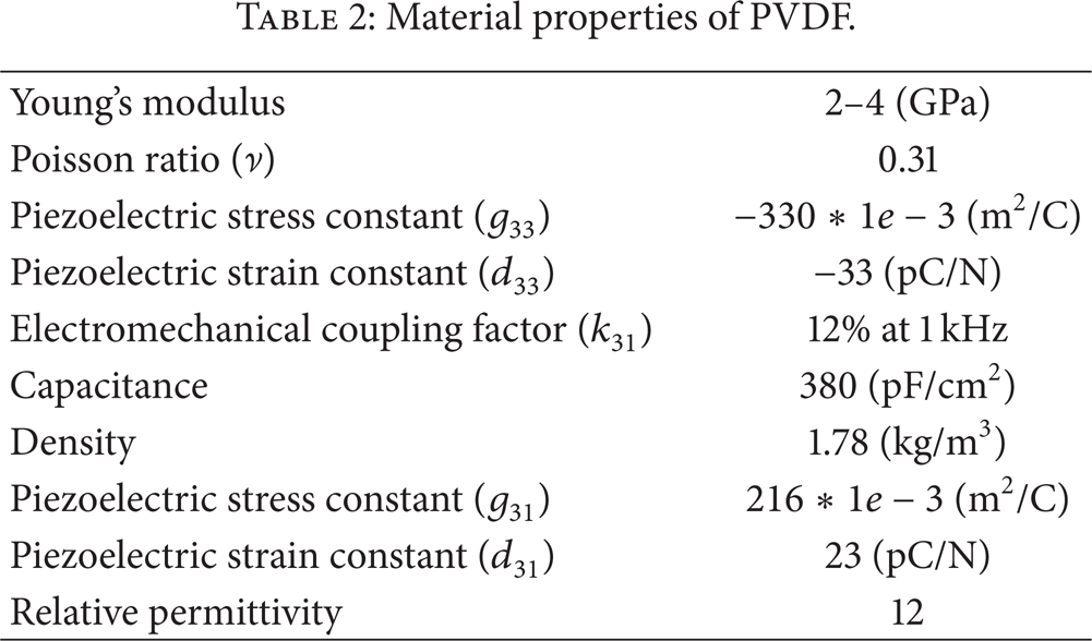
For several decades toward the middle of 1960s, piezoelectricity was investigated as a common property of biopolymers, including natural biological materials that form the structure of plants, animals (whale bone), and humans (tendon). This began an intense search for other organic materials that might exhibit piezoelectricity. In 1969, Kawai found very high piezoactivity in the polarized fluoropolymer, polyvinylidene fluoride (PVDF). While other materials, like nylon and PVC, exhibit the effect, none are as highly piezoelectric as PVDF and its copolymers. Piezoelectric films are commercially available since 1981. The schematic diagram of PVDF is shown in Figure 2. PVDF used in this work is rectangular piezofilm with silver ink screen printed electrodes. Lead attachment is accomplished using a riveted lug going to 300 mm of 28AWG wire. A thin urethane coating over the active electrode area prevents oxidation to the top surface of the silver ink. PVDF is a flexible, lightweight, tough engineering plastic available in a wide variety of thicknesses and large areas. PVDF element has wide operating frequency range from 0.0001 Hz to 1 GHz and low acoustic impedance which can be close match to water and human tissues. In addition, PVDF has high stability with resisting moisture, oxidants, and intense ultraviolet radiation. PVDF can be applied to vibration control of flexible structure, speakers, and printers as an actuator. PVDF can be applied to strain gages, accelerometer, hydrophone, and keypads. The typical material properties of PVDF are listed in Table 2.
Material properties of PVDF.

Configuration of PVDF.
3. Experimental Apparatus
For the experimental verification of MFC and PVDF sensor performance, smart beam structure is prepared as shown in Figure 3. The length, width, and thickness of the aluminum beam are 200 mm, 20 mm, and 1 mm, respectively. MFC and PVDF are attached on top and bottom surface of the aluminum beam at the same location of 9 mm apart from the clamped end of the beam. The photograph of MFC and PVDF sensor used in this work are shown in Figure 4. The length, width, and thickness are 28 mm, 7 mm, and 0.3 mm for MFC and 30 mm, 12 mm, and 0.04 mm for PVDF, respectively. Experimental setup for operational bandwidth, linearity, and durability test is prepared as shown in Figure 5. Aluminum beam is clamped on the shaker and measured signals from MFC and PVDF are sent to personal computer through pulse analyzer. Tip displacement of the beam structure is measured by laser sensor and measured signal is also sent to personal computer through data acquisition system. Excitation signal is generated by function generator and is applied to the shaker. In order to test robustness of the sensors, one more MFC is attached on the top surface of the beam structure as a disturbance source as shown in Figure 6 (a) and experimental setup is prepared as shown in Figure 6 (b). By considering mode shapes of the beam, the location of MFC2 is determined between nodal points of 2nd mode and 3rd mode. Signal generator makes disturbance excitation and is applied to MFC2 through high voltage amplifier.

Configuration of smart beam structure.
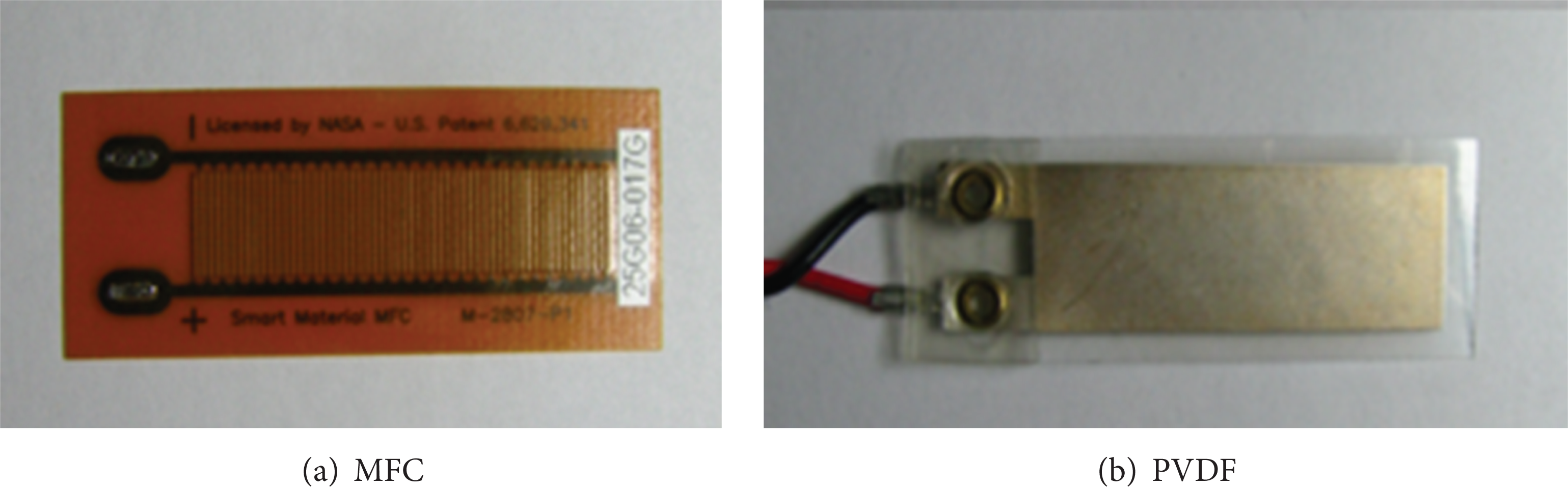
Photograph of sensors.

Experimental apparatus for performance evaluation of MFC and PVDF.

Experimental apparatus for robustness test.
4. Results and Discussions
From the data sheet of MFC and PVDF, the operational frequency ranges are up to 10 kHz and 10 GHz for MFC and PVDF, respectively [19, 20]. For the verification of operational bandwidth of MFC and PVDF sensors, sine sweeping excitation is applied to the proposed smart beam structure from 0 Hz to 5 kHz in this work. In order to compare frequency responses according to frequency range, experiments are conducted for low (0 Hz∼0.5 kHz), middle (0.5 kHz∼3 kHz), and high (3 kHz∼5 kHz) frequency ranges. The measured frequency responses are presented in Figure 7. The frequency responses in the low, middle, and high frequency range are presented in Figures 7 (a), 7 (b), and 7 (c), respectively. As shown in Figure 7 (a), the measured first, second, and third natural frequency is identified by 25 Hz, 151.3 Hz, and 414.4 Hz, respectively. It is clearly observed that both MFC and PVDF can have good sensing performance from 0 Hz to 5 kHz operational frequency range and are well matched with each other. The frequency response, corresponding phase, and coherence responses from 0 Hz to 5 kHz are presented in Figures 7 (d), 7 (e), and 7 (f), respectively.

Frequency response of the smart beam structure.
The linearity of sensing signal of MFC and PVDF is experimentally evaluated. The tests are performed under excitations with the first three mode natural frequencies. The excitation magnitude is increased linearly and then the sensor output is measured for every constant excitation magnitude. The excitation magnitude is presented by using tip displacements of the smart beam structure and laser sensor is used to measure the tip displacements. The linearity test results are presented in Figures 8 (a), 8 (b), and 8 (c) for 25 Hz, 151.3 Hz, and 414.4 Hz excitation, respectively. For the 25 Hz excitation, the tip deflection is increased from 0.3 mm to 0.6 mm with 0.1 mm increment and corresponding sensor output is measured. The tip deflection is increased from 0.1 mm to 0.5 mm with 0.1 mm increment and from 0.01 to 0.0175 with 0.0025 mm increment for 151.3 Hz and 414.4 Hz excitation, respectively. As shown in Figure 8, it is clearly observed that sensor output voltage is linearly increased as the excitation magnitude is linearly increased. It can be concluded that MFC and PVDF have good linearity for sensing performance.

Linearity test results of the sensors.
The durability of MFC and PVDF sensor is experimentally evaluated during 360 minutes. The proposed smart beam is excited with 25 Hz, which is the 1st mode natural frequency, for 360 minutes. In order to monitor the variation of excitation signal of the shaker, an accelerometer is attached to the shaker. The sensor output is measured every 30 minutes and the test results are presented in Figure 9. It is observed that MFC and PVDF sensors have good durability performance and can be used as a monitoring sensor of the structural vibration for a long time. A tiny variation of MFC and PVDF sensing signal is caused by limit of shaker performance, and it can be also observed from the acceleration signal of the shaker.

Durability test results of the sensors.
The robustness test of MFC and PVDF sensor is conducted by applying disturbance signal during the sensing. The proposed smart beam structure is excited by shaker with 25 Hz. Then disturbance signal is applied to the structure by applying 8 V/mm of electric field to another MFC (MFC2 in Figure 6). The test results are presented in Figure 10 and excitation frequency of disturbance signal is 151.3 Hz, 300 Hz, and 414.4 Hz for Figures 10 (b), 10 (c), and 10 (d), respectively. As shown in Figures 10 (b) and 10 (c), original sensing signals are affected by disturbances, but the influence is very small for both MFC and PVDF. However, as shown in Figure 10 (d), the original sensing signal disappears under very large disturbance for both MFC and PVDF. Since the location of MFC2 has large displacement under the 2nd mode excitation, very large magnitude of disturbance is applied to the structure. The sensing signals subjected to disturbance of 300 Hz, which is in nonresonant frequency region, with different magnitudes are shown in Figure 11. The magnitude of disturbance is increased by increasing applied electric field of MFC2 from 2 V/mm to 8 V/mm. Although the original sensing signal of PVDF is more affected by disturbances compared to that of MFC, it is observed that both MFC and PVDF have enough robustness of sensing performance under suitable magnitude of disturbances.

Robustness test results of the sensors with constant disturbance magnitude.

Robustness test results of the sensors with different disturbance magnitude (300 Hz).
5. Conclusions
In this work, an experimental investigation on the sensing performance evaluation of MFC and PVDF was carried out. After brief review of MFC and PVDF, piezoelectric smart beam structure was prepared by attaching MFC and PVDF on the top and bottom surface of aluminum beam structure, respectively. Experimental apparatus was set up by mounting smart beam structure on the shaker and sensing signal of MFC and PVDF was sent to personal computer through data acquisition system. Operational frequency range, linearity of sensing signal, and durability of MFC and PVDF were experimentally investigated. By attaching another MFC on the surface as a disturbance source, robustness of MFC and PVDF sensor was also evaluated. It is observed that both MFC and PVDF can be used as vibration measurement sensor with good performances.
Conflict of Interests
The authors declare that there is no conflict of interests.