
Abstract
The opening process of creep-thermal fatigue crack (CTFC) is studied by finite element method, considering the bilinear kinematic hardening and creep characteristic of the material. The crack is closed under the compressive thermal stress during the heating and insulating processes. The tensile stress during the late cooling process, which is normal to the crack face, makes the crack gradually open. At this time, the temperature of material around the crack has become lower than the creep temperature; therefore, the creep fracture mechanism parameter C* is not applicable. The CTFC is quite shallow, and comparatively the plastic zone is rather large; thus, the method of stress intensity factor is restricted. A modified J-integral method is put forward according to the stress analysis of CTFC, which has been proved to be path independent and valid. The method is used for not only the CTFC but also any unloading crack or the crack in the residual compressive plastic strain field. Experimental results show that the modified J-integral can be used as the controlling parameter of the CTFC propagation.
1. Introduction
For damage-tolerant design and remaining life prediction of high-temperature components, it is important to investigate creep-fatigue crack growth behavior [1, 2]. A large number of studies on creep-fatigue crack growth have been reported in recent years. Most of them are on the crack under creep thermomechanical fatigue (TMF) conditions which refer to a thermal cycling loading with an additional mechanical loading.
Typical creep thermomechanical fatigue model works with one side fixed, and the other side under cycling external load, the temperature cycles with the external load. The TMF crack opens under tensile load, and the crack opening displacement increases continuously with the combination effect of tensile holding load and temperature; thus, the TMF crack propagation can be thought of as the combination in some way of crack propagation caused by TMF and creep. The crack propagation caused by TMF can be characterized by using stress intensity factor or J-integral as a controlling parameter, and crack propagation caused by creep can be characterized by using creep fracture mechanism parameter C* as a controlling parameter [3–5].
In addition, there are cooling duct in nuclear power plant, solar panel of aircrafts in low earth orbit, pulsed high power laser driver, hot work die, roller of the hot mill, cylinder of high power diesel engine, brake disk of high-speed trains, and other components working under creep-thermal fatigue condition, which refers to a pure thermal cycling. Comparatively, the study on the controlling parameters of CTFC is paid less attention [6–8].
Creep-thermal fatigue model is fixed on both sides and there is no external load. During heating process, compressive elastic strain generates in the specimen; during insulating process, compressive creep strain generates in the specimen; and the cracks keep closed in both heating and insulating processes. However, how could creep-thermal fatigue crack grow? Actually, the inelastic strain generating during the heating and insulating processes could not recover freely. Therefore, the tensile stress, which is normal to the crack faces and generated in the late cooling process, makes the crack open and grow. Thus it can be seen that there is really quite a difference between the mechanism of creep-thermal fatigue crack and that of the thermomechanical fatigue crack; the control parameter of the creep thermomechanical fatigue cannot be used directly on the creep-thermal fatigue crack.
Considering the bi-linear kinematic hardening and creep characteristic of the material, the CTFC is analyzed by the finite element method and its controlling parameters are studied accordingly.
2. Modeling and Material Properties
2.1. Modeling Assumption
For convenience, the actual component can be simplified to a rectangular plate (30 mm × 10 mm) fixed at both ends, as shown in Figure 1 (a). Assume that the plate is in the plane stress state. The temperature of the left side changes according to the curve shown in Figure 2 and the temperature of the right side is always 30°C. A crack lies in the center of the left side and is enlarged in Figure 1 (b). RA and RA′represent the crack faces (0.7 mm).R is the crack tip.
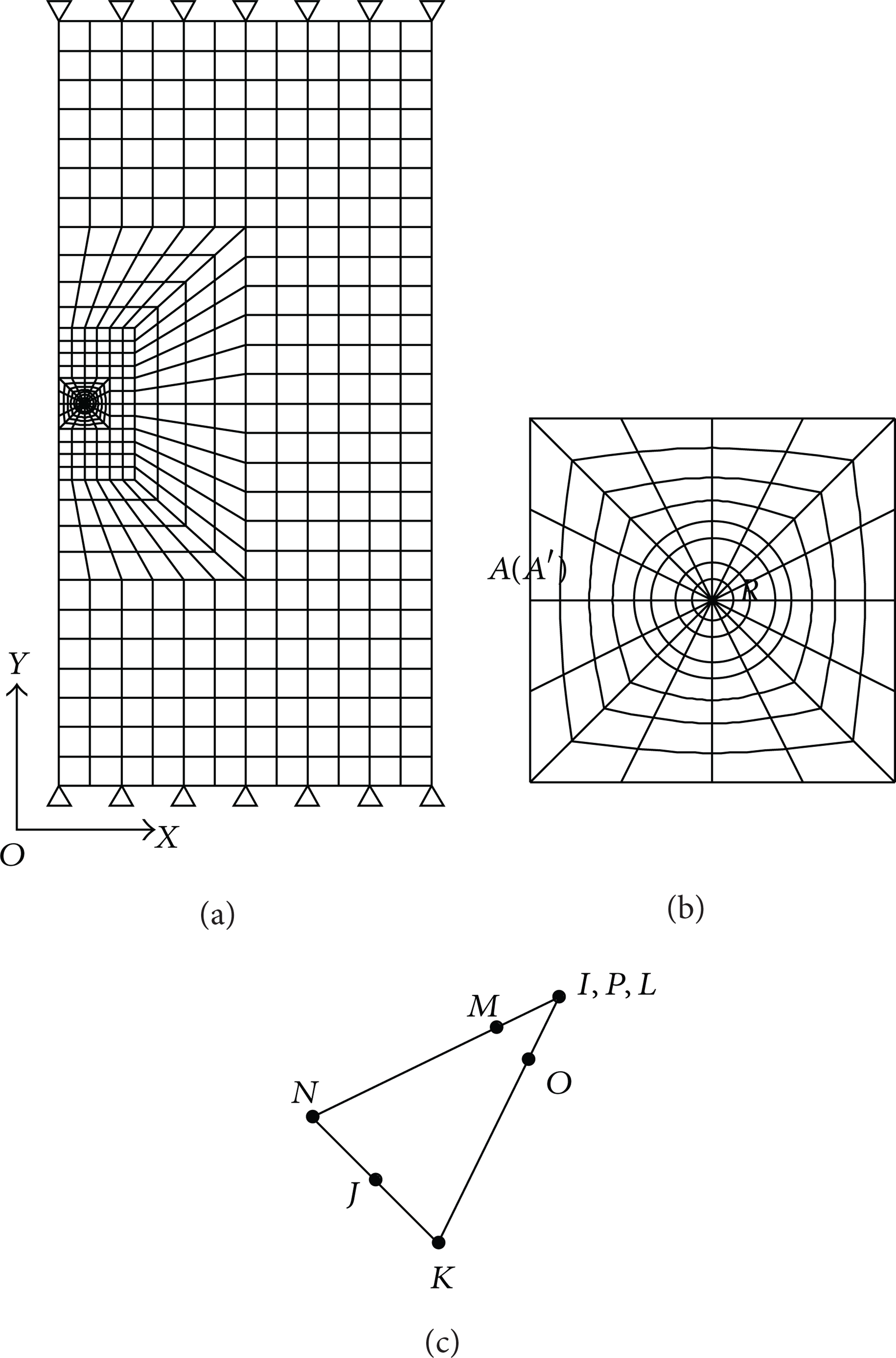
Finite element model.

Temperature curve.
Generally, in the finite element model, the adjacent elements share one node to make the elements connect with each other into a whole. In the finite element model with cracks, simulated crack elements have a fully coincided node position on crack faces as is shown in Figure 1 (b), the elements on both the up and down sides of the line AR. To simulate the extrusion of the two crack faces during the heating and insulating processes, contact elements are used. To measure the singularity of the crack tip, the elements around it should be quadratic, with the midside nodes placed at the quarter points. Such elements are called singular elements (Figure 1 (c)). The mesh size at the crack tip is 0.03 mm.
2.2. Mechanical Properties of Material
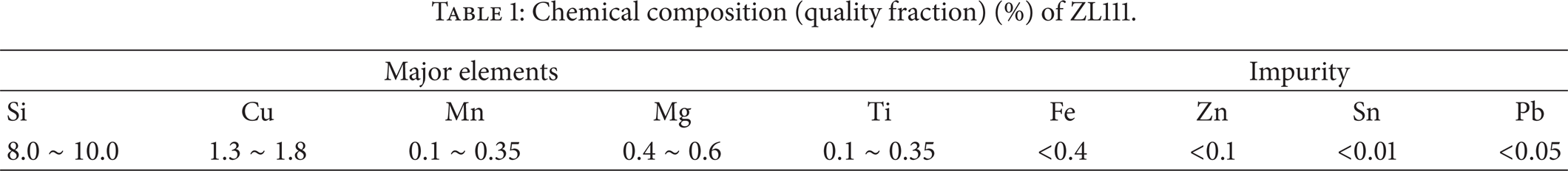
ZALSi9Cu2Mg (ZL111) is a kind of cast aluminum alloy, and its chemical composition is shown in Table 1. It is often used to cast the large diesel engine cylinder heads of naval vessels that are subject to thermal fatigue and creep damage in service.
Chemical composition (quality fraction) (%) of ZL111.
ZALSi9Cu2Mg (ZL111) has superior mechanical properties under the room temperature and high temperature. It is the material with bi-linear kinematic hardening [9], as shown in Figure 3, where OABC is the actual tensile curve, and A is the yield point. After yielding, the relationship of stress and strain is nonlinear. According to the bi-linear kinematic hardening rule, curve ABC can be replaced by straight line AC, and CDEF represents the unloading process.

The bilinear kinematic hardening model.
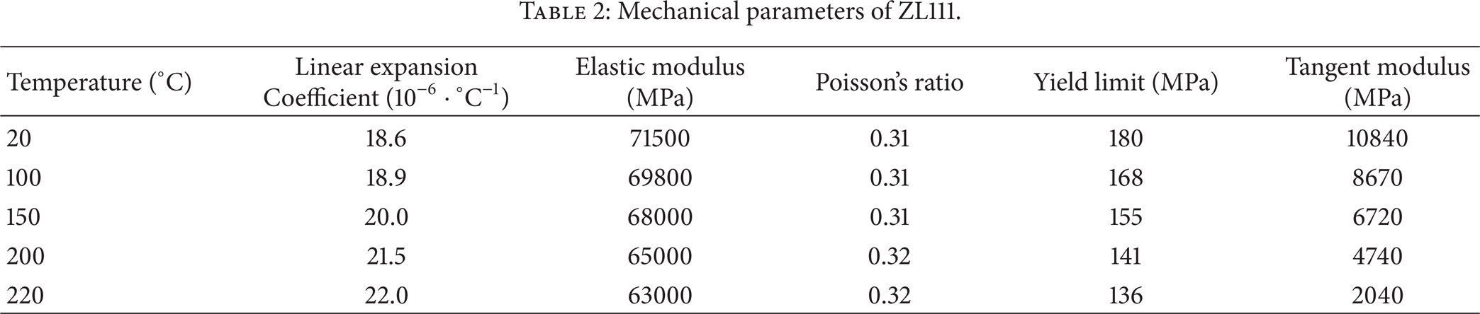
The creep equation of ZL111 is [10]

where
Mechanical parameters of ZL111.
3. Stress Analysis of CTFC
The commercial finite element package ANSYS and the sequential coupling analysis method are employed to compute the thermal stress. First, the initial conditions and boundary conditions for a thermal analysis are set to the model to obtain the temperature field of the model at every discrete time. Then, put the nodal temperature as the coupled-field loads and the structure boundary conditions to the model for a stress analysis. The stress and strain fields at every discrete time can be obtained. The temperature field is just the thermal load for the stress analysis rather than the objective of the paper, and so it is out of discussion.
Figure 4 shows the stress curve of the crack tip (R point) in one cycle; it is obvious that the Mises equivalent stress is dominated by the Y component. Its Y components of strain are shown in Figure 5.

Stress components of the crack tip.

Strain components in the Y direction of the crack tip.
In the heating process (0–10 min) the thermal strain increases with the temperature and the model cannot expand freely due to the restrictions at both ends, so compressive elastic strain and stress are produced;the plastic compressive strain appears when the stress reaches the compressive yield point of the material. In the insulating process (10–90 min), compressive creep strain appears in the common role of compressive stress and time; simultaneously, the elastic compressive strain and compressive stress decrease and the thermal strain and the plastic strain keep constant. In the cooling process (90–100 min), the thermal strain and compressive elastic strain gradually disappear, and the model trends to its initial shape. Because the model is fixed at both ends and the compressive plastic and creep strain cannot get back freely, the tensile stress which is normal to the crack faces is produced.
If the tensile stress reaches the reverse yield point, the material will yield reversely. The crack opens gradually with the increase of tensile stress.
The pressure on points A and R is shown in Figure 6. In the heating process (0–10 min), the pressure on the crack faces increases, for the temperature of point A is higher than that of point R, so the pressure on point A is higher. In the insulating process (10–90 min), the pressure on the crack faces decreases slowly owing to stress relaxation; the creep rate of point A is larger, so its pressure decreases more sharply. In the cooling process (90–100 min), the pressure declines rapidly; the pressure on points A and R becomes zero at 95 min, which proves that the two crack faces separate at this time. Figure 7 shows the displacements in the Y direction of points A and A′ as well as their relative ones.
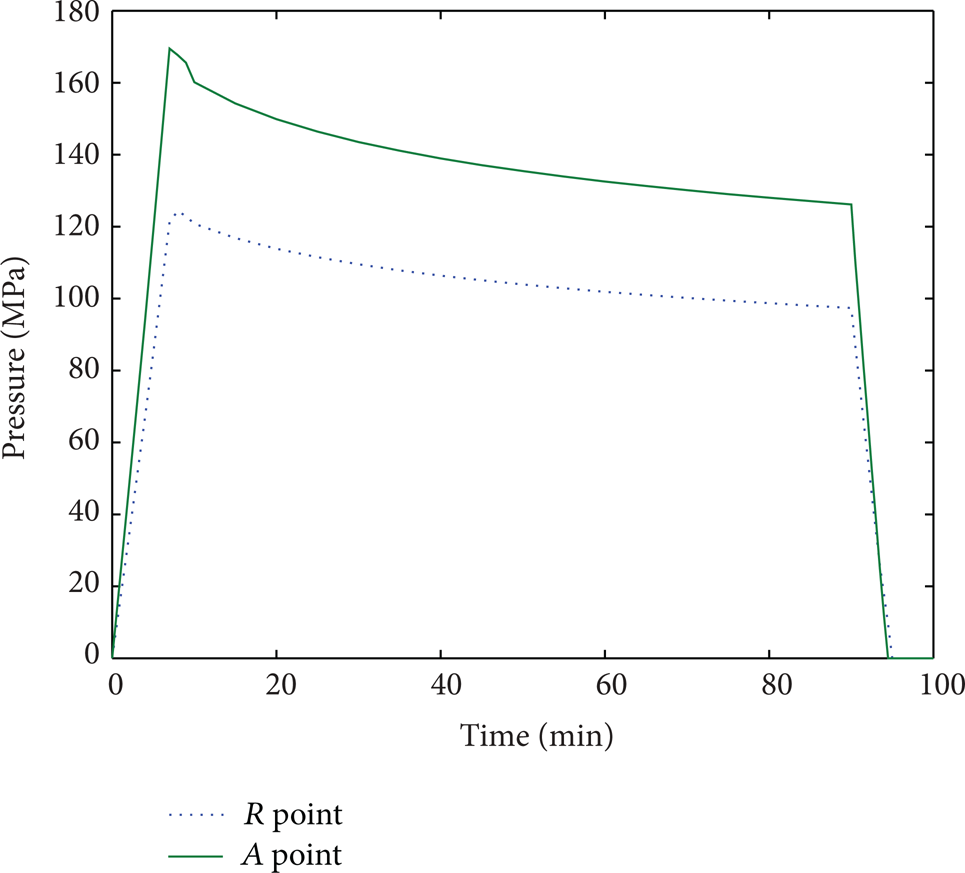
The pressure on points A and R.
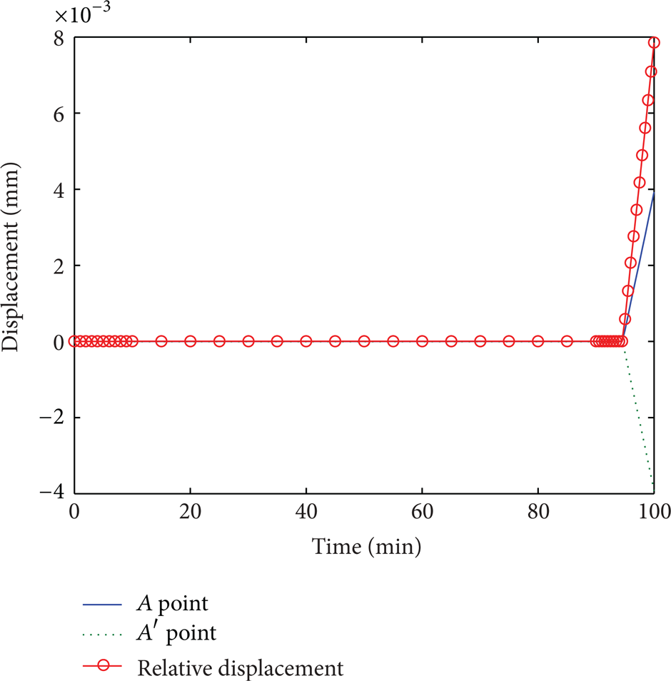
The displacements in the Y direction of points A and A′as well as their relative one.
Figure 8 is the deformation of the crack region at 100 min (the deformation is magnified to 10 times). The red area around the crack tip is the tensile plastic zone outside which is a green area. Some compressive plastic strain produced in the heating process remains here in various extents, so it is called compressive plastic zone.
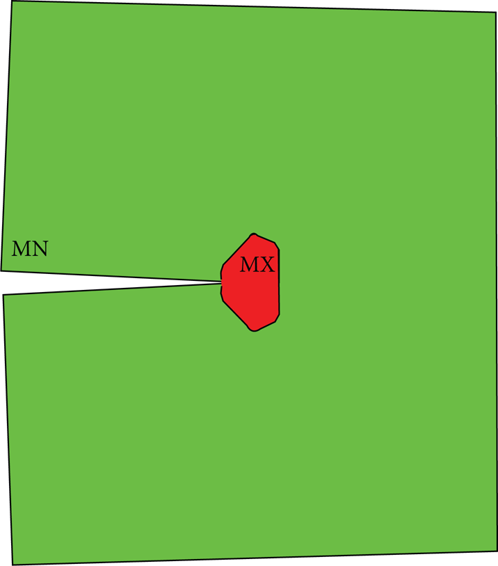
The deformation of the crack region at 100 min.
One point is picked up in each of the tensile plastic zone and compressive plastic zone randomly, marked as T and C. Figure 9 gives the strain components in the Y direction of points T and C. Figure 10 gives their Y components of stress. From the figures, stress and the elastic strain of the two points get to zero at the moment of the crack opening, which is just as the crack tip.

Strain components in the Y direction of points T and C.

Stress components in the Y direction of points T and C.
According to the above analysis, it can be deduced that the compressive plastic strains produced in heating and compressive creep strain produced in insulating cannot come back freely during cooling, which will make the CTFC open. It can be also concluded that the more the compressive inelastic strain is during heating and insulating, the larger the tensile stress, the tensile strain, and the opening displacement of CTFC will be at the end of cooling.
4. Controlling Parameters of CTFC
The CTFC opens gradually in the late cooling process. At this time, the temperature of the material around the crack has become lower than the creep temperature. Therefore, the creep fracture mechanism parameter C* is meaningless to the CTFC. Suppose the stress intensity factor or J-integral will be the controlling parameter of the CTFC in the following.
4.1. Stress Intensity Factor Method
The stress intensity factor of a crack for a linear elastic fracture mechanics analysis may be computed, according to a fit of the nodal displacements in the vicinity of the crack [11, 12]. In the small-scale yielding condition, the factor can be modified according to [13].
Generally, the small-scale yielding condition for a crack length a is [13]

where r p is the size of plastic zone; here it is the mean distance from the boundary of the tensile plastic zone to the crack tip. The CTFC is always quite shallow [6]; comparatively, the plastic zone is rather large. The small-scale yielding condition can be satisfied, only when the singularity of the crack is small.
4.2. Proposition of a Modified J-Integral Method
The classical definition of J-integral is given by

where γ represents any path surrounding the crack tip; s is the distance along the path;
From the previous stress analysis of the CTFC, the thermal stress near the crack does not load monotonously in a temperature cycle, which does not meet the path-independent condition. Moreover, affected by the residual compressive plastic strain field at the end of cooling, the integral might be negative. Thus, the J-integral method must be improved to applicable to be the CTFC.

where n is the unit outer normal vector to path γ. It is obvious that the later term ofthe J-integral is naturally path independent, and immune to the compressive plastic strain field.
According to the plastic deformation theory, the strain energy density is represented by

where σ ij , ∊ ij (i, j = x, y) are, respectively, the stress and strain components. Here only the improvement of w yy similar to that of w xx and w xy is discussed in detail.
From the stress analysis of the CTFC, the Y components of stress and elastic strain around the crack can be zero almost at the same time when the crack opens. Moreover, the cooling period can be regarded as a monotonic loading process. Thus, only the strain energy in this period should be computed.

where t1 stands for the moment of the opening, and t2 is the terminal time of cooling. In order to eliminate the effect of the residual compressive plastic strain field, ∊ yy (t) is obtained as
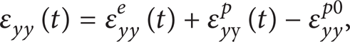
where ∊yy e (t),∊yy p (t) are separately the elastic and plastic components of strain at the end of cooling; ∊ yy p0 is the compressive plastic strain produced in the heating process.
The improvement of J-integral is put forward according to the analysis of CTFC according to its definition. The integral computed in this way is path independent. Thus, it could be the controlling parameter of CTFC.
In the linear elasticity, small-scale yielding conditions, and plane stress conditions, J-integral is related to stress intensity factor by the following relationship

where E is the elastic modulus. Therefore, the stress intensity factor KΙ can validate the modified J-integral cursorily.
5. Examples
Take a group of concentric circles, whose center is crack tip and radius is r, as the integral paths. Figure 11 shows the relation between the modified J-integral and r/r p . Clearly, the modified J-integral is path independent as long as the integral path is within the compressive plastic zone.

The relationship of J-integral and r/r p .
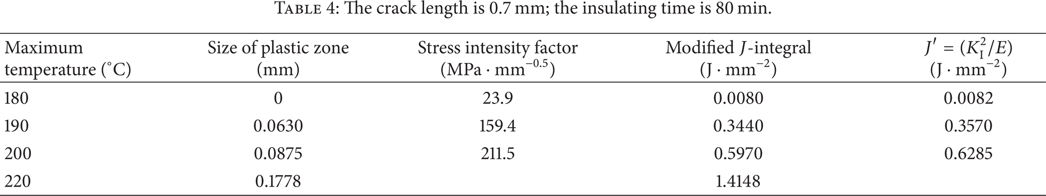
The stress intensity factor and the modified J-integral are calculated under different conditions. The results are shown in Tables 3, 4, and 5. In (8), the elastic modulus E is 71175 MPa.
The crack length is 0.7 mm; the maximum temperature is 210°C.

The crack length is 0.7 mm; the insulating time is 80 min.
The maximum temperature is 200°C; the insulating time is 80 min.
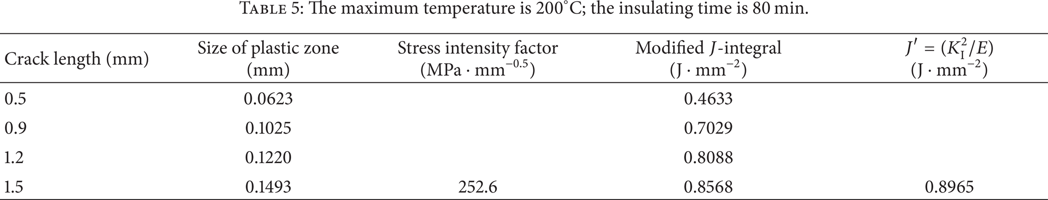
It is obvious that the stress intensity factor and the J-integral increases when the insulating time prolongs, the maximum temperature increases, and the crack grows. From calculating, the stress intensity factor can be used as the controlling parameter of the CTFC only with a low heating temperature, a short period of holding time, and a deep crack.
6. CTFC Propagation Test
The creep-thermal fatigue test machine is composed of clamping mechanism, infrared radiation heating device, hydropneumatic cooling system, and control system. The operational principle of the creep-thermal fatigue test machine is shown in Figure 12; the specimens can be turned upside down by the driving shaft, which makes it easy and quick to heat and cool the specimens. The detailed size of the specimen with cracks is shown in Figure 13. The first, second, and third specimens are used in the creep-thermal fatigue test, the temperature of the specimen cycles isfrom 30°C to 210°C, and the thermal cycle insulating time is 5 minutes at 210°C every time. All the specimens undergo 1000 thermal cycles. The length of the crack is detected for each 100 cycles, and the results are shown in Figure 14.

Operational principle diagram of the creep-thermal fatigue test machine. 1: driving shaft, 2: stock of the specimen, 3: unloading bolt, 4: tightening bolt, 5: infrared radiation heating device, 6: specimen, 7: hydropneumatic cooling system, and 8: arm of the test machine.

Specimen of creep-thermal fatigue.
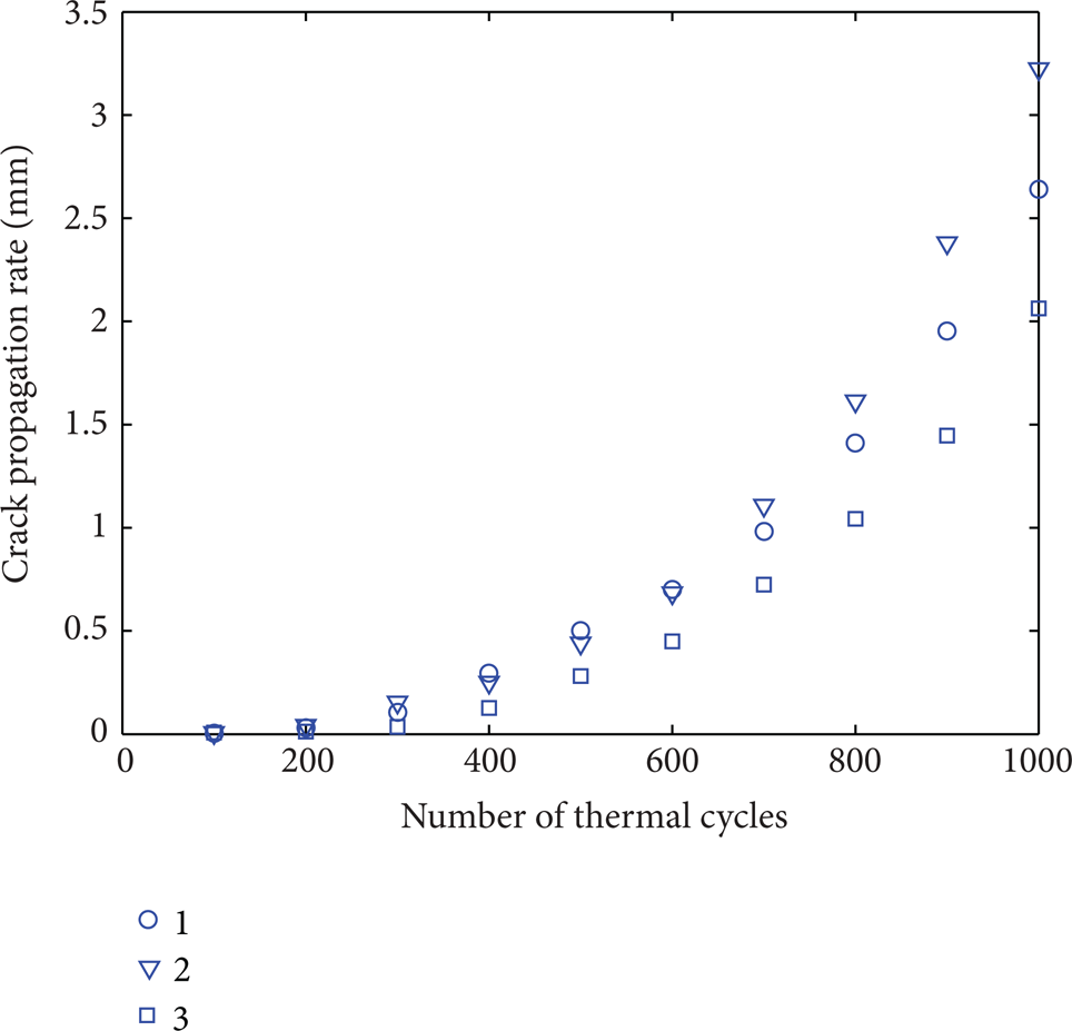
Propagation length of the CTFC.
The secant method [14] is used to measure the crack growth rate, that is to calculate the gradient between two adjacent data points on the a-N curve to get the crack growth rate as

where da/dN is the crack propagation under one thermal cycle, Δa is the crack propagation under ΔN thermal cycles, a i and N i are the crack length and number of cycles of load corresponding to the ith data point.
According to the Paris formula,

where,C and n are constants related to material property, environmental media, and the geometry of the specimen.
The creep-thermal fatigue J-integral value in corresponding conditions can be obtained according to the modified J-integral method referred to in the front of the paper the data points of ln (da/dN) and ln J are shown in Figure 15; hence, n = 2.51, C = 8.72 × 10⁻⁶ can be obtained by some regression analysis of formula (10) using these data points.

7. Conclusions
The crack is closed under the compressive thermal stress during the heating and insulating processes. Because the inelastic strain generating in the two processes cannot be back by itself, the tensile stress during the late cooling process, which is normal to the crack faces, makes the crack gradually open. When the CTFC is opening, the temperature of the material around it has become lower than the creep temperature; therefore, the creep fracture mechanism parameter C* is not applicable. The stress intensity factor and J-integral can be used as the controlling parameters. The stress intensity factor can be used only with a short insulating time, a low maximum temperature, and a deep crack. The J-integral should be modified in order to be applicable to the CTFC, that is to take the moment of opening as the starting of the strain energy density integral and eliminate the effect of the residual compressive plastic strain by (7). It has been proved that the modified J-integral method is path independent and valid. It is used for not only the CTFC but also any unloading crack or the crack in the residual compressive plastic strain field. The stress intensity factor and J-integral increase when the insulating time prolongs, the maximum temperature rises, and the crack grows. Experimental results show that the modified J-integral can be used as the control value of the CTFC propagation. The research on the controlling parameters of CTFC provides the theoretical basis for its growth.
Footnotes
Acknowledgments
This project is supported by the Natural Science Foundation of Liaoning Province (Grant no. 201102167), Aeronautical Science Foundation of China (Grant no. 20110450001), Liaoning Excellent Talents in University (Grant no. LJQ2011012), and the Science Program of Shenyang (Grant No. F12-069-2-00).