
Abstract
It is an effective method for port-based ontology (PBO) to be used to represent and organize product design information and, support product conceptualization. As port is used to map and link components together, it plays an important role in capturing component information. This paper establishes a design method of compliant mechanism based on port ontology. Firstly, the coding rules are constituted based on PBO, and knowledge base of compliant mechanism is constructed, which includes stiffness base and inherent frequency base of flexible cells. Secondly, incidence matrix is established to denote the relationship of components, and based on incidence matrix design, schemes are generated by adopting the genetic algorithm. Thirdly, by selecting suitable parameters, scheme populations are generated towards training neural network (NN), and the trained NN model is employed for choosing preferential schemes to be satisfied with users' demands. At last, an application case is given to demonstrate the conceptual design of compliant mechanism based on port ontology.
1. Introduction
Port-based ontology, as an approach to be involved in product design, has been effectively applied to conceptual description of a product. Ontology has been known as an important means to represent design knowledge in the stage of product development. In general, a consistent and sharable description of design knowledge can be summarized as a fundamental concept for capturing the functional knowledge. Such specification of conceptualization is generally called ontology [1].
PBO modeling has been viewed as an effective approach to supporting conceptual design [2]. Methods to be used for matching multi-information, such as functions and constraints, should be further developed. This has been demonstrated by a great lot of work reported in the literatures [3–5]. Port compatibilities are used to map and link two components, which makes it possible to build incidence matrix and allow designers from different backgrounds with various interests to access the functional ontology of components [6].
Researchers have explored multidesign methods to apply to analyze design activities such as axiomatic design, quality function deployment, and theory of inventive problem solving (TRIZ) [7]. At the early stage of design processes, the components constitute the fundamental building blocks of these activities. Benefitting from the varieties of computer aided design research and various methodologies, a rich library set of components has been developed [8]. However, there is no agreement upon standard component library to share with their design processes. As a result, the libraries of components are independently developed on the basis of the domain knowledge. One goal of this research is to obtain flexible component library that can be available to interrelated designs. It is not to capture all component types that physically exist but to create a function-based hierarchical framework of subcategories in order to represent component design knowledge and obtain design alternatives.
It plays an important role in precise positioning and displacement for compliant microdriving mechanism. The flexible cells transfer energy, force, and motion through the deformation of flexible components. Furthermore, they are easy to fabricate due to their monolithic nature. Being lack of friction and wear, compliant mechanism is ideally suited towards obtaining precise motion [9]. Type synthesis of the flexible component and the mechanism structure are the decisive factors which determine its performance [10]. Kinematic characteristic is considered at every stage of designing process including preliminary design. For compliant mechanism, the general design method is to estimate all the structure parameters experientially in advance and then analyze its stiffness and inherent frequency. Unfortunately, this process depends mainly on one's experience, and the result usually does not best meet the given requirements. Being devoid of systematic theory foundation, the parameter design method is blindfold and difficult to be put into practice [11].
This paper is to explore the conceptual design theory of compliant mechanism targeting towards content original structure parameters, stiffness, and inherent frequency and also to provide a framework for the latter work and the entire process of design. The rest of the paper is organized as follows. At first, the prototype components of compliant mechanism are introduced; Secondly, PBO component taxonomy and PBO knowledge support for conceptual generation are expounded and analyzed; thirdly, the flow graph of compatibility and solving matching rule is laid out; at last, a case study is given to demonstrate the process of a design scheme generation.
2. Prototype Components of Compliant Mechanism
In general, the prototype components of compliant mechanism are from the rigid mechanism. However, they have a big difference in many respects such as work environment, precise, purpose, manner, linkage, and cost. The similarity between rigid links and flexible behavior makes it easy to scheme out the prototype from rigid mechanism based on kinematic approaches. Table 1 takes a comparison between rigid mechanism and compliant mechanism. Also flexible cells are listed in Table 2, and they include compliant girders and flexible hinges in compliant mechanism.
Rigid mechanism and compliant mechanism for enlarging displacement.
Flexible cells of compliant mechanism.
3. PBO Taxonomy of Compliant Mechanism
3.1. Component Attributes
Three kinds of attributes called taxonomy (TA) are used for capturing each component: descriptive attributes, physical attributes, and functional attributes. They are represented in formula (1) [6]:
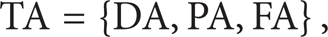
where DA stands for descriptive attributes which particularly include part number, feature quantity, part description, and assembly information. PA means physical attributes which include part weight, type of material, and parametric information such as height, width, length, inside/outside diameters, and thickness. They are physically measured for each component and recorded into the database. FA represents functional attributes which describe each component function, acting interfaces, connectability, and so on.
3.2. Port Attributes
Port, as the location of intended interaction between component and its environment, plays an important role in the product conceptual design. In a system the relationship of component and its port is described in formula (2) [4, 12]:

where IOC represents a component; INT indicates the interaction between i and j component; and C ij stands for the connection between i and j. In addition, i, j, k, and n are integers, in which k stands for the number of connection and n for the number of components.
The proposed port taxonomy plays an essential role. The definition of function based on the classes of hierarchical component provides a consistent means of representing component design knowledge that is used for subsequent computational design synthesis. The taxonomy of port attributes is shown in Figure 1.

The port attributes of flexible mechanism.
3.3. PBO Incidence Matrix and Coding Rules
The taxonomy allows us to capture specific relationships between functional needs and components that are used to build incidence matrix.
Port not only constitutes the interface but also defines the boundary of two components. PBO can be expressed with vertex G and edge E as follows [6]:

where G stands for the component number of a product and E means the relationships between two components. Considering a product with three components, vertex G and edge E can be used to build a relation matrix as follows:

Also, the relationship between component and function can be further described on the basis of attributes of PBO connection. Figure 2 presents the process of incidence matrix generation. Four levels of function-form relations are considered in the proposed incidence matrix. The first one is at the contact relation level, and it corresponds to contact types of two individual components of a product. The second one is at the moving relation level, and it corresponds to the moving relation of two individual components. The third one is at the port type level, and it corresponds to port types of a component in different energy domain. The last one is at the constraint relationship level, and it corresponds to constraint types of two individual components of a product.

The process of generating incidence matrix.
Figure 2(a) stands for the matrix of the corresponding components, in which “1” means that they exist in the corresponding relationship. Contrarily, they are marked as “0.” Figure 2(b) gives the corresponding structural graph. Figure 2(c) represents incidence matrix with port attribute, in which CAB, MAB, P t , and TAB are the functional attributes, as shown in Table 3 in detail [6].
The coding rules of compliant mechanism.

4. PBO Knowledge Support for Conceptual Generation
4.1. PBO Prototype Base for Components
The attributes of port include type, contact relationship, moving relationship, constraint relationship and capability, and complexity. Therefore, port attribute performance (PAP) is further expressed in the following:
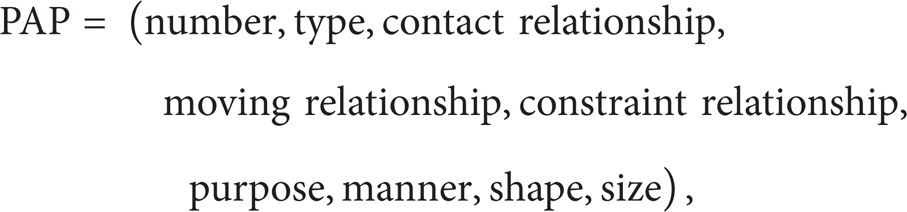
where purpose stands for what the PAP is used for and manner means how the PAP works. For example, according to formula (5), PAP of the port E12 is expressed below (see Figure 2):

where PAP.shape and PAP.size are provided from the prototype base and also the parameters of PAP.shape are defined on the basis of PAP.size.
In addition, for E12, parameters include variables (R1, s1, and b), which are put into the prototype base. R1 and s1 are indicated in Figure 3(b), and b means the thickness.
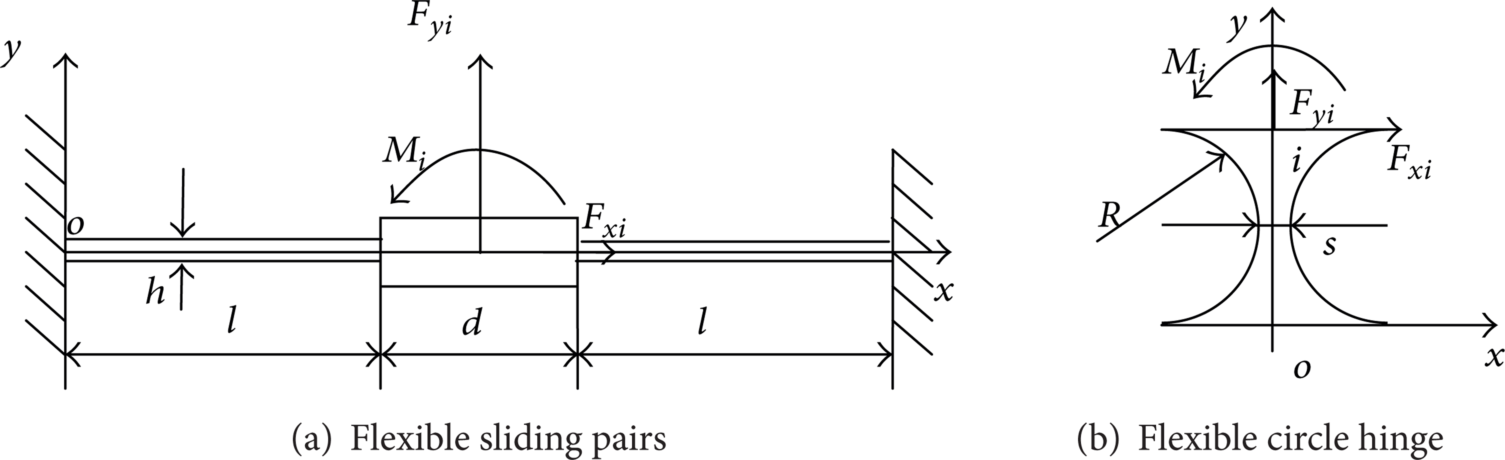
Two flexible cells.
4.2. Flexible Cells' Stiffness Base and Vibration Frequency Base
Flexible cells are the hinge of compliant mechanism. The influence of its stiffness is essential for the whole compliant mechanism.
Figure 3 presents two flexible cells; one is flexible sliding pairs as shown in Figure 3(a) and the other is circle hinge shown in Figure 3(b), in which u i represents the displacement of the middle point i and F i represents the outside force of the point i. They are particularly expressed in the following:

The stiffness model formally describes the relationship between the displacement and the force, as shown in formula (8) [13]:

where

where
Also a quantitative formula can be given for the other flexible hinges. And the formulae of c x are not listed for them here.
Every flexible cells' stiffness can be determined according to their geometric relationships and constraint energy distributions. For any given precision requirements, the structure parameters can be modified based on the stiffness-parameters relationship model.
The algorithms libraries of finite element are also established to associate the vibration frequency and the structural parameters of the flexible cells. The detailed arithmetic is described in [14].
4.3. The Base of the Flexible Cells' Parameters
Figure 4(a) is an example of compliant mechanism for enlarging displacement; the amplificatory ratio theoretically is l3/l2 and actually is d2/d1 because of the stiffness of every flexible cell. The stiffness of the compliant mechanism is influenced by the flexible cells' parameters. For example, in the flexible sliding pairs shown in Figure 3(a), if parameters l are larger, then the stiffness of the hinge will become smaller. It is the same as for other parameters. All value scopes of the parameters and their representations are recorded in the libraries of the flexible cells. For the mechanism in Figure 4(a), the parameters indexing from the libraries of the flexible cell are shown in Figure 4(b). The robustness of amplificatory ratio d2/d1 depends on the stiffness of all the flexible cells in the mechanism.

Parameters indexing from the libraries of flexible cells. The amplificatory ratio of displacement is d2/d1.
5. Compatibility and Scheme Generation
5.1. Compatibility
The conceptual design solutions can be obtained from the functional decomposition and the associated constraints for a specific design problem. It includes the function and constraint attribute, the relations between these attributes, and the methods that are used to construct the conceptual solutions. It may be constructed in the hierarchy by inheriting the definition from its higher level class. The methods defined for the conceptual solutions include operations such as function queries, adding a new function, modifying and deleting a function, defining a new constraint, and firing an existing constraint [15]. When these operations are performed, the integrity of the whole object can be described by indexing knowledge libraries corresponding to port ontology. The flow graph as shown in Figure 5 is the process of obtaining the preference scheme of compliant mechanism.
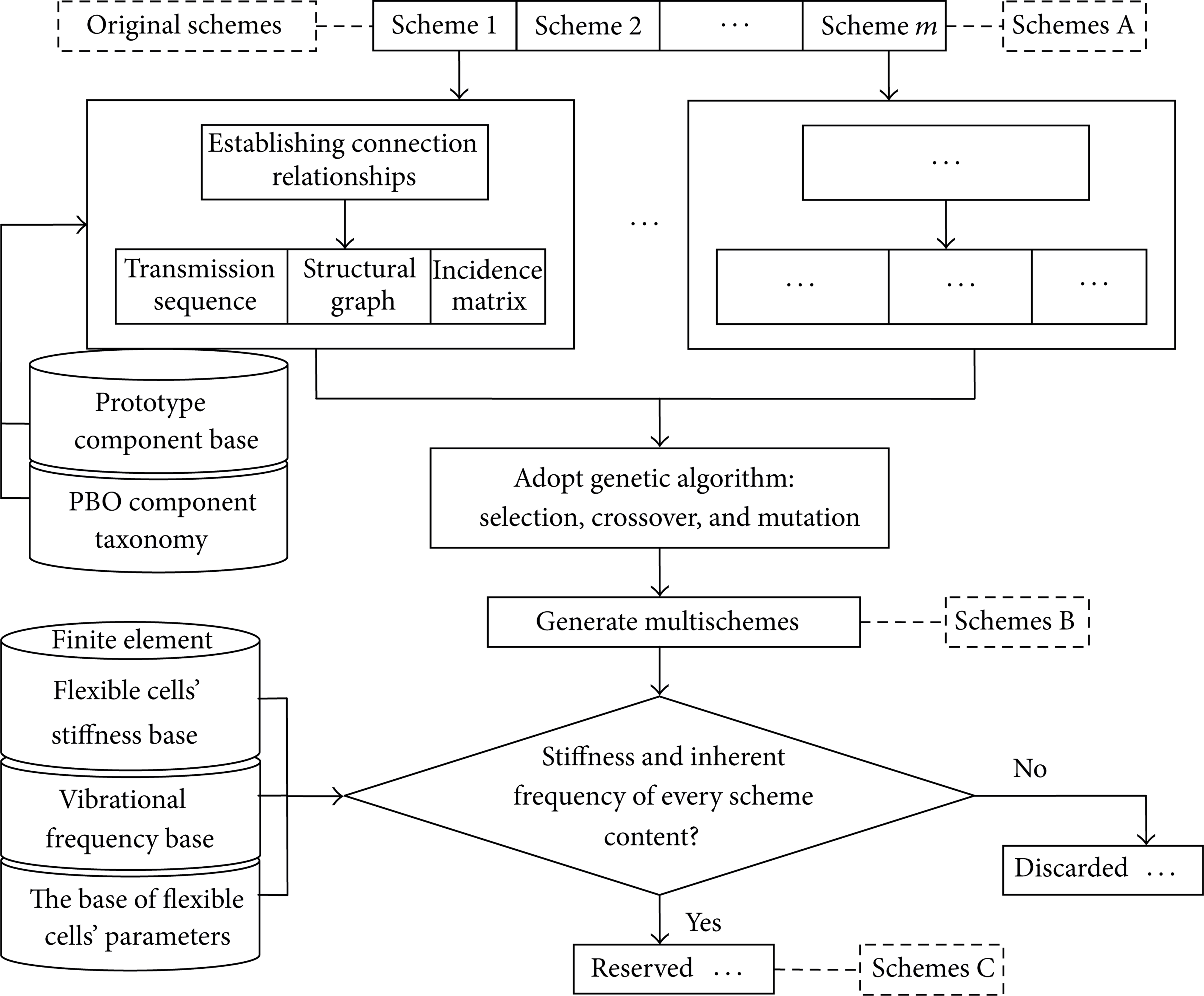
The flow graph of scheme generation based on PBO.
5.2. Multischemes Generation
Hinge types are optional at the same level such as circle hinges, ellipse hinges, rectangle hinges, and rounded rectangle hinges. The process of multischeme generation adopts a roulette method to select from genetic algorithms as shown in Figure 6(a). The algorithms of crossover, and mutation are also employed in Figures 6(b) and 6(c). Scheme populations (schemes B in Figure 5) are to be increased using selection, crossover, and mutation.

Genetic algorithms.
Setting a range with eligible or preferable stiffness and vibration frequency, the inconsequent ones are discarded while proper ones (schemes C in Figure 5) are reserved by filtering those schemes (schemes B in Figure 5).
5.3. Neural Network Model from Sample Schemes
It is a challenge to assign an appropriate value to each parameter so as to obtain an optimum scheme. The value of each parameter in the scheme (schemes C in Figure 7) will influence the design objective. Every parameter is designated several different values in the range of its boundary, which are defined in the base of flexible cells' parameters. For example in the cell in Figure 3(b), s, b, and R are three parameters. Generally considering convenience in matching operation for all cells in the mechanism, thickness (parameter b) is appointed the same value, while R and s are alterable parameters. If there are two appointed values respectively for R and s, there are four combinations for R and s, as shown in Table 4. Hence there are four schemes of different parameters values. And they are viewed as to be sample schemes (schemes D in Figure 7).
R and s combinations.

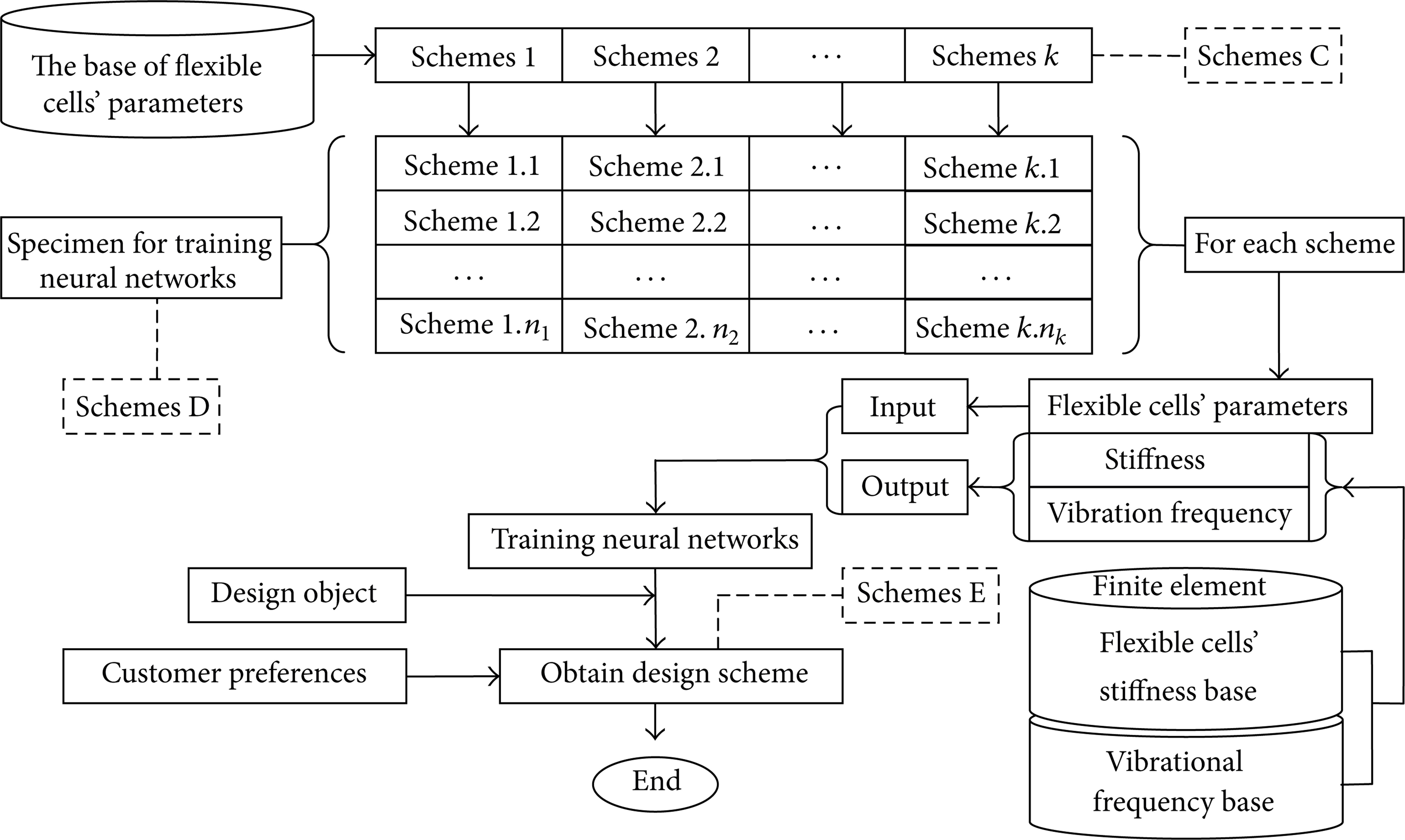
Obtaining preferable schemes.
Another group schemes (schemes D in Figure 7) are produced by selecting different values for every parameter. All these schemes (schemes D in Figure 7) are as the specimen for training neural networks. Subsequently two trained NNs are obtained, flexible cells' parameters as input and respectively stiffness and vibration frequency of the system as output.
6. Case Study
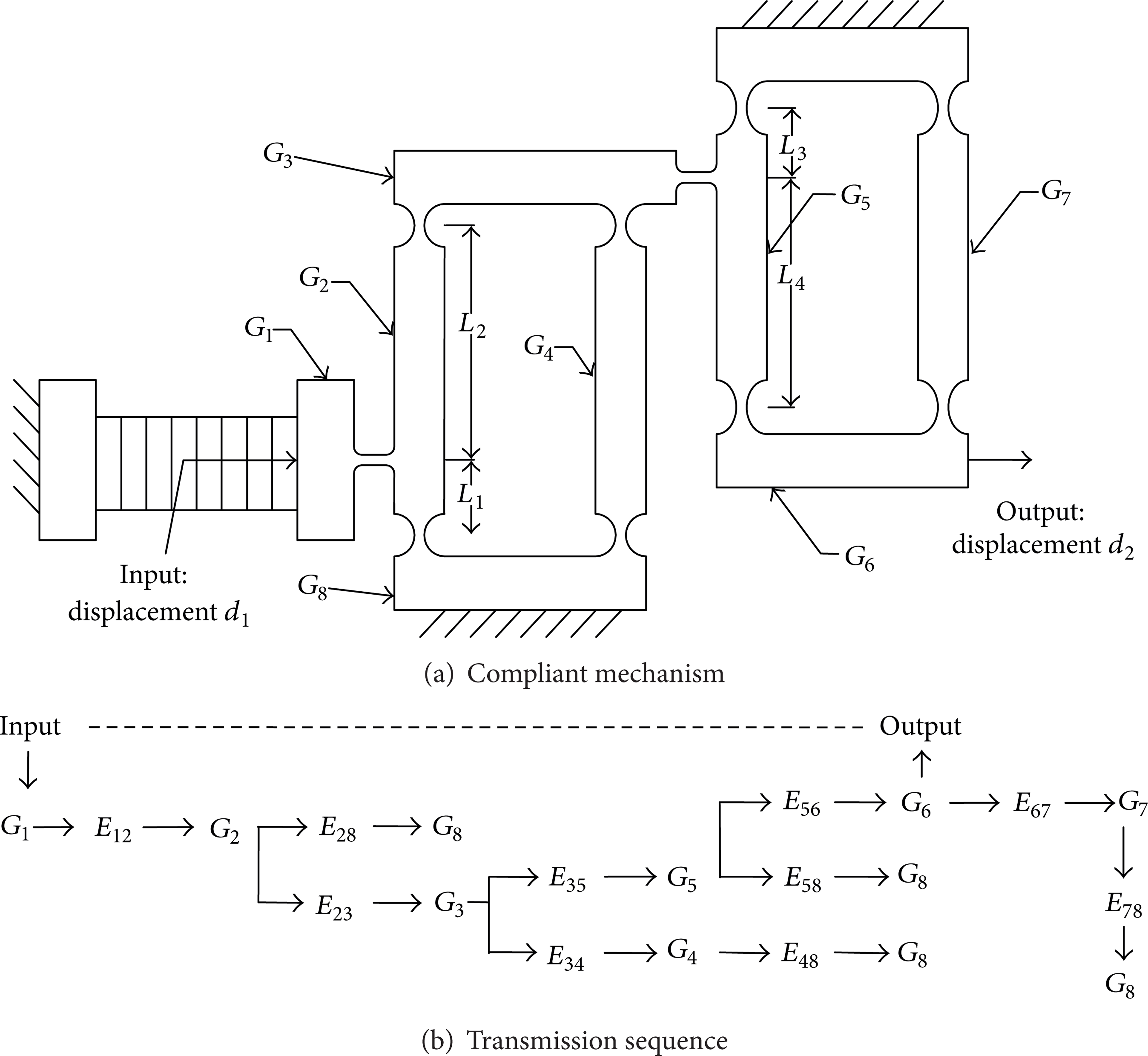
It is increasingly used in precise mechanism for the microdisplacement amplification mechanisms with flexible hinges [11]. The significant performance parameters, including input displacement, output displacement, and robustness of amplification ratio, are very important for analyzing and designing the mechanism. Two of the original schemes are shown in Table 1. Firstly, to obtain a large amplification ratio, to connect in series two or more original schemes is adopted; hence structural graph and incidence matrix of each scheme (schemes A in Figure 5) are generated. Secondly multischemes (schemes B in Figure 5) are generated by adopting genetic algorithm with PBO modeling, transforming port taxonomical codes to implement iterative design process, and reconstructing system design schemes. Thirdly, by choosing the different values of the parameter, group schemes (schemes D in Figure 7) are generated as the specimen for training neural networks. The nonlinear mapping relation between structural vibration frequency and structural parameters as well as between stiffness and structural parameters is built up by training the artificial neural network with the specimen (schemes D). At last the structural parameters, which met the design requirements aiming at inherent frequency and stiffness, are obtained from the trained neural network. Figure 9(a) gives one result of compliant mechanism for enlarging displacement, which is chosen from customer preferable inherent frequency and stiffness. Figure 9(b) shows the transmission sequence of all the components and the relation between ports and components. The amplificatory ratio desired is 30. 30 is assigned to the two series parts (see Figure 9(a)) and each is

Microdisplacement amplification mechanisms.
Microdisplacement amplification mechanisms.
Thus, eight components and ten hinges are obtained in the mechanism shown in Figure 8. The hinges E23, E34, E48, and E28 are at the first grade. The hinges E56, E67, E78, and E58 are at the second grade. The hinges E12 and E35 are the transitional linkages. The relationship between input and output is nonlinear. So it is necessary for error compensation feedback to input in the precise positioning and displacement. The port between G6 and G1 is information port. The sensor returns displacement of output component G6 to the input component G1 instantaneously to adjust the offset between input and output in real time. The structural graph and incidence matrix are shown in Figure 8.
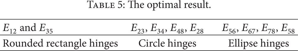
The attributes of circle hinges, ellipse hinges, rounded rectangle hinges, and components G1–G8 are indexed from the prototype base. The boundary of flexible cells' parameters is determined from the parameters base. Contact relationship of E23, E34, E48, E28, E56, E67, E78, E58, E12, and E35 is chosen by adopting roulette wheel selection. The result is shown in Table 5. E12 and E35 are the transitional linkages, and optimal result is rounded rectangle hinges because of its flexibility. E23, E34, E48, and E28 are in the first grade, whose distortion is low. The optimal result is circle hinge because of circle hinge's large rigidity. E56, E67, E78, and E58 are in the second grade, whose distortion is large, and the optimal result is ellipse hinges to fit.
The optimal result.
7. Conclusions
The paper presents a PBO method to generate design schemes of compliant mechanism. It is convenient for PBO to link multicomponents into a product system and implement conceptual design. Incidence matrix can capture not only geometrical information but also nongeometrical information such as port functions and constraints. It can be used to represent the preliminary design in two different but interrelated domains, namely, function domain and physical domain. The two domains are linked through function-form mapping relations that allow the designers to identify possible design solutions through function reasoning. Furthermore, the product is to be modeled on different levels of abstraction corresponding to the port ontology knowledge in different stages of the design process. Incidence matrix is preponderant to increase the number of scheme populations by the multiobjectives of genetic algorithm. The inappropriate schemes are discarded, and they are not suitable to aiming at stiffness and vibration frequency of the system. At last, using trained model of neural networks, the design scheme is selected according to customer preference. However, the paper only refers to the conceptual design of plane compliant mechanism. The coding rules of compliant mechanism are also aimed at plane mechanism. Further study will be needed and extended for the space mechanism design.
Footnotes
Acknowledgments
This research is partially sponsored by the NSFC (Grant nos. 50775065 and 51275152) and Science Foundation of Hebei Province (Grant nos. E2008000102 and E2013202123).