
Abstract
A variable structure controller is designed for a high-speed underwater vehicle on a catastrophic course using a mathematical model. This sudden change at the moment when a high-speed underwater vehicle launches out of the water seriously affects the stability and the control accuracy of the high-speed underwater vehicle. The nonlinear system is linearised via input-output feedback linearisation using differential geometry theory. The attitude tracking controller is designed for a closed loop using the exponentially approaching rule of variable structure theory. The simulation results show that the control system can be applied to a catastrophic course in a high-speed underwater vehicle launched underwater and out of the water. The results also show great robustness against all admissible uncertainties for system parameter perturbation.
1. Introduction
A high-speed underwater vehicle is a type of stratagem weapon that is essential for naval equipment because it can be used in deep water and can control large areas of the sea. The motion of a moving body is a system with unmodelled dynamics and an input uncertainty. It has a control system that meets the requirements of large distance runs and high-precision tactics, but it is vulnerable to the impacts of model input uncertainty, so its trajectory control systems are subject to an increased focus with respect to performance and energy efficiency. Because of an increasing number of commercial and military equipment applications, a new study launched out-of-water tasks involving a manipulator, which gave rise to challenging control problems. The manipulator's motion process is generally experienced in two stages: “in the water” and “air.” The biggest problem is that the features experienced by the vehicle body in the underwater section are different from those in the air. The buoyancy and added mass are zero after the high-speed underwater vehicle comes out of the water and the mathematical model changes suddenly at that moment. The control system should be able to learn and to adapt to changes in the high-speed underwater vehicle dynamics and its environment.
Yoerger and Slotine [1] proposed a series of SISO continuous-time controllers by using the sliding mode technique on an underwater vehicle. Cristi et al. [2] and Papoulias et al. [3] proposed an adaptive sliding mode controller for high-speed underwater vehicles based on the dominant linear model and the bounds of the nonlinear dynamic perturbations. In recent years, advanced control techniques have been developed for high-speed underwater vehicles and are aimed at improving the capability of tracking the desired position and attitude trajectories. Poorya et al. [4] proposed using an adaptive controller, which was shown to be suitable to compensate for ocean current disturbances. Nambisan and Singh [5] designed a multivariable adaptive autopilot for the dive-plane control of submarines. Based on a backstepping design approach, an adaptive control law is derived for the trajectory control of the depth and the pitch angle. In [6] Luo and de la Sen's indesign of the switching hyperplane for a class of uncertain systems involving internal delays is given. The same authors in [7], proposed a methods for the design of sliding mode controller with state feedback, static output feedback and dynamic output feedback. In order to reduce the conservatism, a composite sliding surface is dedigned for global decentralised stabilisation of a class of interconnected time-varying delay [8]. Additionally, the current study focuses on the analysis and simulation of supercavitating characteristics, and in application, the mentioned above methods are complex.
The feedback linearisation can shield the nonlinear features of the system and can provide input-output linear decoupling with a closed-loop form. Variable structure control is insensitive to parameter changes and disturbance and does not need online identification. Additionally, its physical realisation is simple. In this paper, differential geometry and variable structure control are combined to design a controller for the catastrophic course out of water. The control strategy not only takes advantage of a nonlinear transformation to simplify the control system design, but it also makes use of the invariant features of the sliding mode on the system perturbation and disturbance.
2. Feedback Linearization
2.1. Mathematical Model of the Catastrophic Course out of Water
According to fluid dynamics theory, a nonlinear model of a high-speed underwater vehicle is derived as follows:

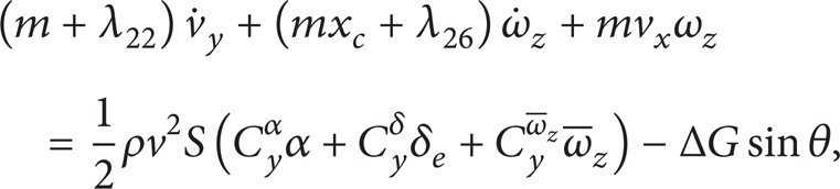


For the water-gas transition, the reduced acceleration produced when the high-speed underwater vehicle leaves the water is caused by the added mass of the fluid, steady-state flow, gravity, buoyancy, and surface friction. In the initial impact phase out of water, the steady-state resistance, buoyancy, and surface friction are all small. The momentum equation for the transition phase out of water is derived as follows (neglecting surface friction):

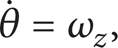
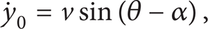
The kinetic equation is as follows:

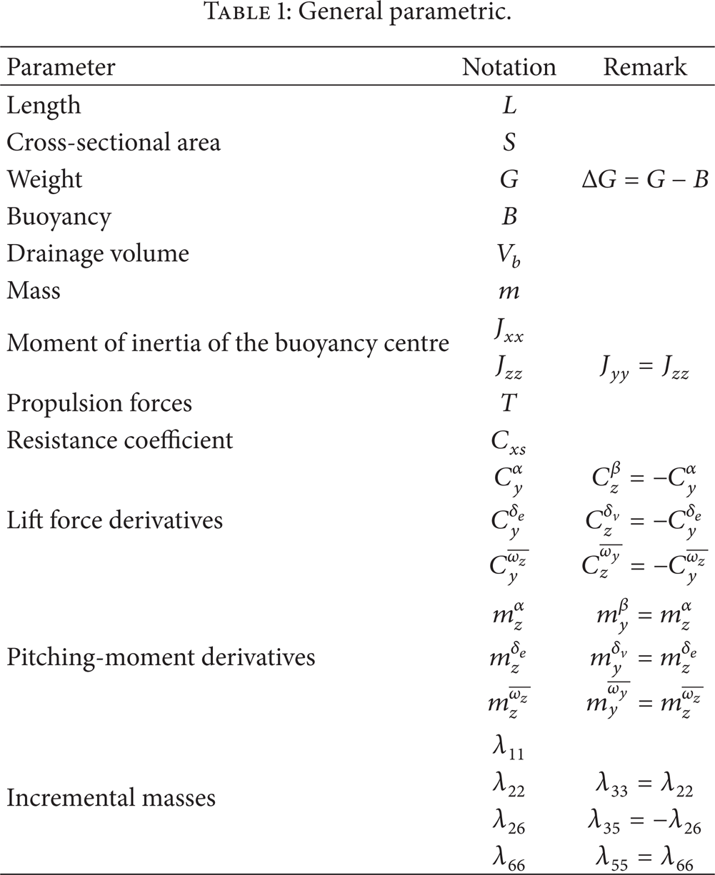
In the formula
General parametric.
Define the system state vector

In this paper, the controller is only designed for the former model, and the model after the high-speed underwater vehicle is out of water is regarded as an uncertaintyin the modelling:

2.2. Input-Output Linearisation of a High-Speed Underwater Vehicle Nonlinear Equation
For the affine nonlinear system [9],

where x ∊ R n , u ∊ R1, and y ∊ R1 are the system states, input vectors, and output vectors, respectively. Given a function h(x), that is the smooth scalar function and a vector field f(x), the Lie derivative L f h(x) of function h(x) along a vector field f(x) is a new scalar function as follows:
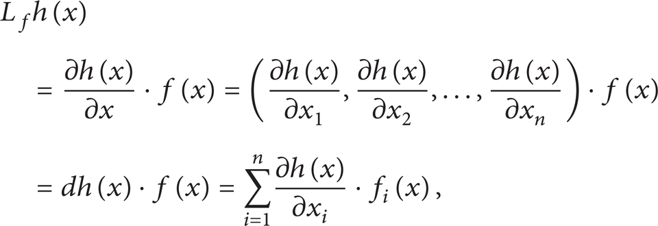
where f(x) = (f1(x), …, f
m
(x))
Generally, for multiple Lie derivative

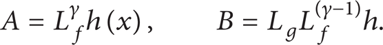
Let γ be the relative degree of y, which is obtained through Lie derivatives:

where L g L f (γ – 1)h ≠ 0, for all x ∊ Uδ(x0). From (16), the input-output relations can be obtained:

where
If matrix B is invertible, the system can be linearised and decoupled by choosing u as follows:

Thus,

The system standard form will be given. Choose the new system states as follows:

The system can be changed into a linearised system:

where

Note that p ∊ Rn – γ, q ∊ R(n – γ) × m. The above state transform Φ: x → (z, η) is a diffeomorphic coordinate transformation that maps x onto a standard coordinate. The feedback control law (19) makes the state vector η unobservable:
If the dynamic within the subsystem is stable, the system is called a minimum phase system. In practical engineering, the phase system usually is not controlled directly, and the states are bounded when joining the input to verify whether the subsystem is controllable.
The controlled attitude angle can quickly track the reference commands, and the flight altitude variation must be controlled. Therefore, state variables relative to altitude are chosen. The system output vector is chosen as follows:

Thus, y = θ.
New state variables are chosen for the system:

Generally, the system decoupled matrix is as follows:
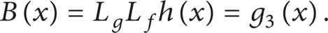
But here, B(x) = L g L f h(x) = g3(x) is a one-dimension matrix scalar function.
The feedback control law is as follows:

Here, the original system is transformed into an equal third-order system as follows:
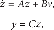
where z = [z1, z2] T , A, B, and C are all in Brunovsky standard form:

3. Design for the Control System of a Catastrophic Course out of Water
3.1. Robustness Analysis of Variable Structure Control
From the application point of view, the main concern is the external dynamic of the linearised system. The external dynamic must be stable and possess good performance. The internal dynamic needs to be stable so that only the robust controller needs to be designed for the external dynamic using the sliding mode control method [10, 11].
As mentioned before, the nonlinear terms of the system can be eliminated by selecting an appropriate set of input transformations. However, the input-output linearisation is only valid for accurately modelled systems. To ensure the robustness of the control system in the presence of system uncertainties, such as the parameter uncertainty or the unmodelled dynamics, the sliding mode control is applied to the linearised system. Considering nonlinear system (13) with uncertainties, (17) becomes the following via input-output linearisation:

where the uncertainties

where c is a positive constant and y d is the desired response. Differentiating (32) yields the following:

To design the robust controller, an idempotent approaching law is selected for the variable structure control, and the input is as follows:

Substituting the control u and (31) into (33) yields the following:

It is intuitive to look for the system to track within a limited time to reach switching curve; the tangent vector must point to this switching curve; that is, when

If
The proper selection of the parameters that satisfy the above conditions guarantees the stability and robustness of the control system. This is a sufficient, but not a necessary, condition, and the system uncertainty is difficult to express accurately. Additionally, a simple nonlinear transformation with an uncertainty will become more complicated. Because of these reasons, the above equations are usually not calculated accurately. From the standpoint of practical engineering, the control objectives can be achieved by adjusting the control structure and parameters.
3.2. Design for the Variable Structure Controller
After the input-output feedback linearisation of the system, the system is decoupled as a second-order linear system. That is,
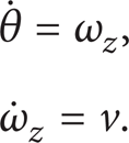
The desired pitch angle is θ. Let the tracking error vector be e = θ – θ d , where θ d is constant.
The switching surface is selected for the system according to (15):

Then,
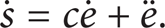
The sliding surface equation is
Substituting the expressions for e and
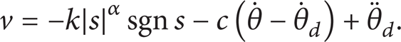
The idempotent approaching law is selected for variable structure control:

where sgn is the sign function. Choosing a small α and a large k can accelerate the speed of normal movement and prevent states from surpassing the switching surface, which may cause great chattering. The control strategy is easily realised in engineering [14].
From (39) and (40), the following control law can be obtained:
Substituting v into (28), its form becomes the same as the form for u described before.
To avoid the inherent chattering phenomenon in the variable structure control system, the method proposed by Burton that makes the function smooth is adopted. That is, [15]
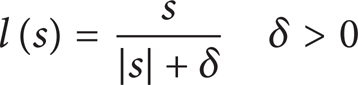
and it will replace sgn(s).
The system structure chart is as in Figures 1 and 2.
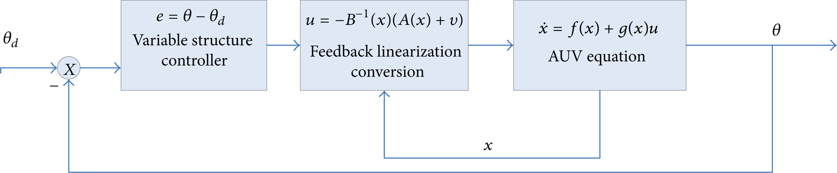
The control system structure block.
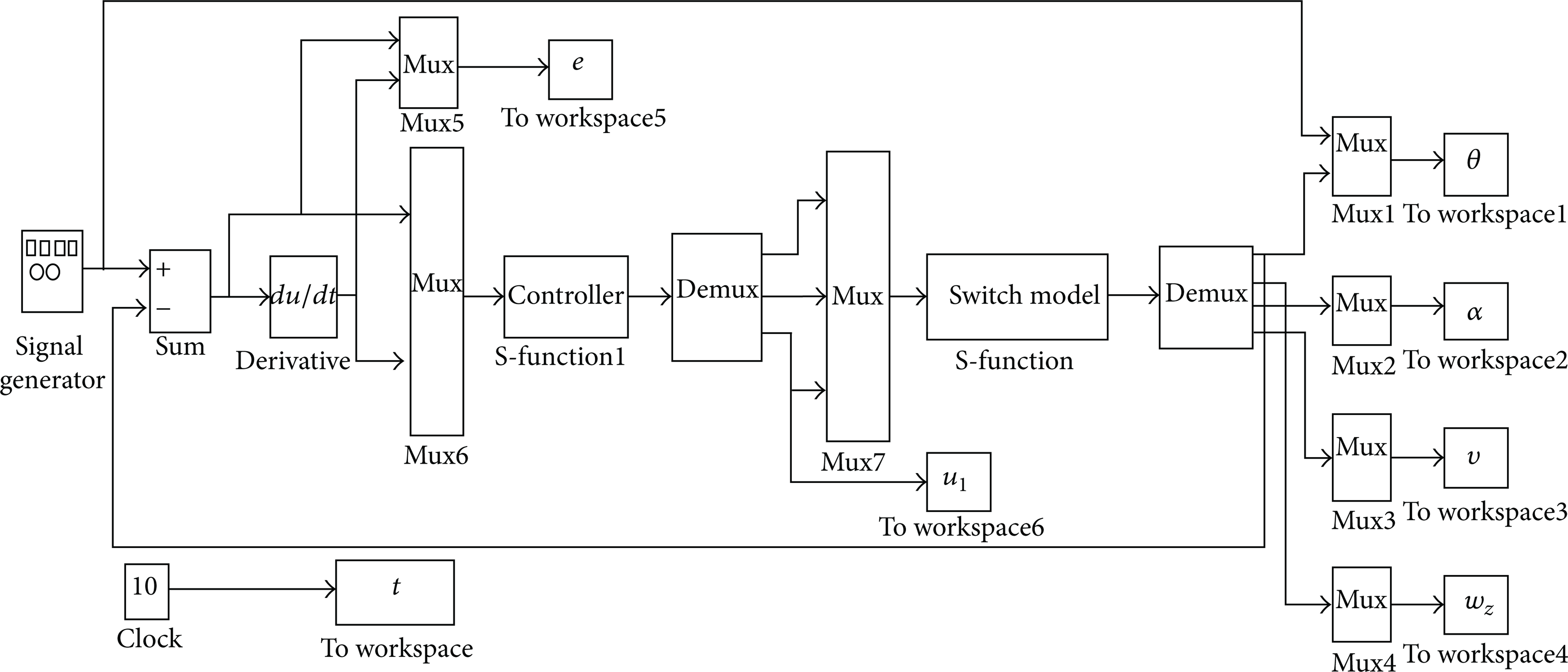
The Simulink main programme structure block.
4. Simulation Results and Analysis
After some experimentation, good performance was achieved with the following parameters.
c = 5, ∊ = 0.01, k = 8, α = 0.5, δ = 0.05. The initial state vector of the high-speed underwater vehicle is x(0) = [20 m/s 0° 0 0°]. The pitch angle tracking command is 20°, and the propulsion force is T = 3.1t. When t = 5s, the high-speed underwater vehicle moves out of the water and its nonlinear model changes simultaneously. However, the controller remains the same as the one used in the former model. As indicated in Figure 3, the system reached equilibrium. Therefore, the transition process is gentle, and the out-of-water process is stable and reliable. The attitude angle tracking error in the system is zero.
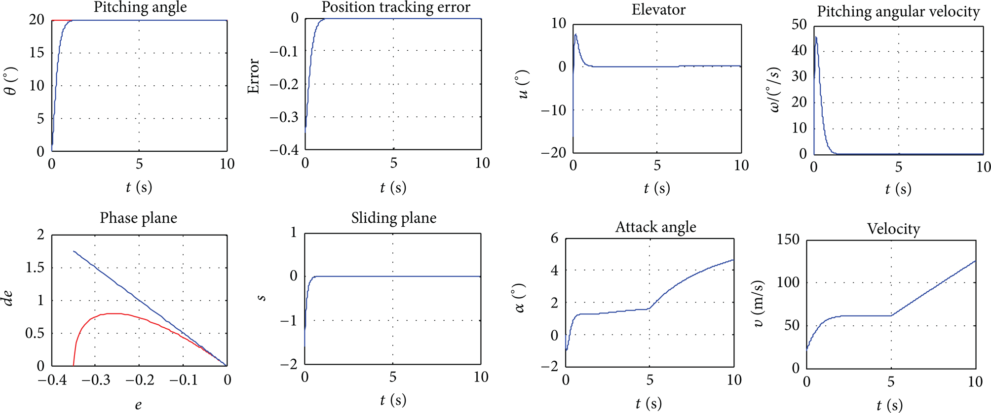
The system response with the accurate model.
The above simulation was carried out based on an accurate model, but unmodelled dynamics always exist. To verify the robustness of the variable structure control, the simulation was done using the maximum hydrodynamic coefficient and minimum uncertainty satisfaction in (18). The variations of the hydrodynamic coefficients, the initial velocity, the initial attitude angle, and so on can all lead to changes in the results of the simulation. Because of the paper length, only one group of simulation maps is made. As indicated in Figure 4, the controller has great robustness against model uncertainties, and the out-of-water process is smooth and gentle, which ensures the attack probability of a high-speed underwater vehicle.

The response of the system with parameter uncertainties.
5. Conclusions
The complex nonlinear differential equations of the high-speed underwater vehicle are linearised and decoupled with no information loss using a nonlinear coordinate transformation, which simplifies the control system design. The new equations take full advantage of invariable characteristic of the variable structure control so that the control system has great robustness against system parameter uncertainties. The simulation results show that the control strategy is effective. There is a high tracking accuracy with a nonlinear controller to ensure that the process out of water is absolutely stable and reliable.