
Abstract
Since wireless sensor networks (WSNs) have a lot of potential capability to provide diverse services to human by monitoring things scattered in real world, they are envisioned as one of the core enabling technologies for ubiquitous computing which organizes and mediates both physical and social interactions anytime and anywhere. WSNs are being adopted in various fields and things in their zones are being monitored. However, existing WSNs are normally designed for observing special zones or regional things based on small-scale, low power, and short range technologies. Seamless system integration at a global scale is still in its infancy stage due to the lack of the fundamental integration technologies. In this paper, we present a global integration avenue of ground monitoring based on WSNs. The proposed avenue includes design, integration, and operational strategies of IP-WSN based territorial monitoring system to ensure compatibility, interoperability, and real-time. Specifically, we offer the standardization of sensing data formats using IP-WSN and database interfaces using EPC sensor network, which enable a spontaneous and systematic integration among the legacy WSN systems. Also, we categorize network topology according to topographic characteristics thereby helping deploy sensor nodes on the real environment. Therefore, the proposed technology would be a milestone for the practically deployable global territorial monitoring systems.
1. Introduction
The idea of ubiquitous computing [1] has been envisioned to organize and mediate both physical and social interactions anytime and anywhere. The recent rapid evolution toward ubiquitous computing environment has been accelerated by enhanced sensors, advancement of cost-effective wireless and mobile network technologies, improved computing power, prolonged battery life, and open software architecture. In the ubiquitous computing, one of the most important and essential technical building blocks is WSN (wireless sensor network) [2–5]. A typical WSN consists of a large number of tiny sensor nodes that have sensing and communication functions. It also has a limited processing and storage resource because of self-powered and low-cost features.
WSNs are deployed in various regions to monitor things [6, 7] by constructing cooperative and self-organizing wireless networks. For several years, a number of public organizations have already deployed WSNs tailored to structural health monitoring (e.g, bridge, building, dam, etc.), home safety/intrusion detection, industrial distribution management, and critical resource/environment surveillance (e.g, fire, flooding, earthquake, etc.). Recently, the organizations further focus on integrated monitoring systems and convergence technologies in order to deliver social security, organize national defense, ensure public safety, and respond to natural disaster. However, existing WSN-based monitoring systems are originally designed for observing particular zones or regional things by using small-scale, low power, and short range stationary sensor nodes with self-developed or standard communication technologies (e.g, ZigBee [8–11]). Although many research efforts have been made to standardize global network communication technologies such as IP-WSN (IP-based wireless sensor network) [12, 13], the realization of a seamless system integration at a global scale is still in an infancy stage due to the lack of the fundamental integration technologies to handle heterogeneous environments and compensate WSN monitoring systems.
In this paper, we present an effective integration avenue of real-time global monitoring based on WSNs. The proposed technology includes design, integration, and operational strategies of an IP-WSN based territorial monitoring system to ensure compatibility and interoperability. The system is designed to monitor ground, environment, and video (image) information of specific territory. For support of real-time monitoring capability, various wireless communication methods including CDMA, HSDPA, Wibro, and TRS are selectively used according to their availability on each geographical region. Our particular contribution is standardization of sensing data formats and their database interfaces, which enables a spontaneous and systematic integration among the legacy WSN systems to construct efficient and effective territorial monitoring systems. We envision that the proposed technology would be a milestone for practically deployable global territorial monitoring systems.
The paper is organized as follows. Section 2 investigates WSN communication technologies which can be used for the real-time territorial monitoring and reviews existing technologies of legacy sensor network systems and their problems. It, moreover, introduces related works about sensor network integration. Section 3 presents hardware and software system designs of the proposed IP-WSN based real-time territorial monitoring integration system. In Section 4, we propose integration approaches among sensor network systems. Section 5 illustrates practical deployment scenarios of the proposed system. Finally, we conclude with future work.
2. Background
In this section, we explain wireless communication technologies to use on WSNs for ubiquitous computing and investigate their pros and cons. And then we introduce existing sensor network systems based on these technologies. We also point out a rational alternative for the standardization and integration of existing monitoring systems and finally introduce related works.
2.1. Communication Technologies for Wireless Sensor Networks
Generally, WSN consists of at least sensor field with sensor nodes and at least sink node. To achieve WSN, sensor nodes communicate among themselves into sensor field and also these nodes communicate with sink node. Their communication technologies mainly adopt WiFi, HSDPA, Wibro, TRS, ZigBee, UWB, Bluetooth, and 6LoWPAN. Their features are briefly described as follows.
For a short range wireless network, WiFi [14] is a wireless LAN standard (IEEE 802.11b) using 2.4 GHz. WiFi support a high-speed wireless Internet using an AP (access point). Generally, mobile communication service providers easily install APs and spread them to many areas, so that WiFi network coverage will be widened. Also, WiFi is faster than 3G. Since most of computers include WiFi devices that allow users to search for and connect to AP, device's compatibility is significantly high. However, as many users can be focused on one AP, its network speed depends on the number of connections to the AP. Also, mobility is not supported because WiFi is only used around AP. For this reason, network technologies considering mobility, HSDPA and Wibro, are required. HSDPA (high speed downlink packet access) [15] is an asynchronous communication protocol for mobile telephone data transmission extending WCDMA (wideband code-division multiple access). It is known as a 3.5G technology and LTE as a 4.0G is currently being used. HSDPA can achieve theoretical data transmission speeds of 14 Mbps and actually take data with the transmission speeds of 2~3 Mbps. Also, applications with high data demands such as video and streaming music focus on HSDPA. HSDPA is available for seamless communication at a highspeed over 100 km/h. It, however, has a limitation on a headcount per base station. As an IEEE 802.16e standard, Wibro (wireless broadband Internet) [16] is corresponding to 3.5G wireless communication technology and Wibro-Advanced is defined by 4G technology. This technology was devised in order to overcome the data rate limitation of CDMA based mobile devices and in order to add mobility to wireless LAN. Since Wibro has the advantages of ubiquitousness, mobile users can access the web, multimedia contents, and whatever information while moving. Wibro base stations provide collected data throughput of 30 to 50 Mbit/s per carrier and cover a radius of 1~5 km. And Wibro provides mobility for moving devices up to 120 km/h. TRS (trunked radio system) [17] is a communication system combining mobility communication and two-way radio. It allows multiple users to share and use one frequency. That is, TRS is similar to an Internet chatting site. In particular, suppose that the site is a TRS service; each channel of the service corresponds to an opened chatting room. The number of users to join in the channel is equal to the permitted number in the chatting room. TRS has an advantage that people or things with the same jobs in relatively small area communicate with each other. For this reason, TRS has been mainly used in urgent work such as that of police men, fire men, and emergency room for a long time. ZigBee [11] is a low-cost and low-power wireless mesh network standard which has been built upon PHY and MAC layers defined in IEEE 802.15.4 [9]. It can construct a WSN system using low-power sensor nodes with the communication frequency of 800 MHz~2.4 GHz and data rate of 20 Kbps~250 Kbps. ZigBee, however, does not directly support IP connectivity. Its sensor nodes may equip various types of PHY/MAC including IEEE 802.15.4 PHY/MAC as an underlying layer beneath the adaptation layer. As an ultrawide band providing low power, UWB [18] which is used for communication and for radar based applications does not use a wireless broadcast wave and uses wide frequency (GHz) in base band. It can share a frequency without interference between existing wireless systems and existing communication systems by using a narrow pulse such as nano- or picosecond. Generally, UWB provides a high-speed communication of low power across a very large area in proportion to the existing spectrum with over 100 Mbps (3.1~10.6 GHz). However, it requires an intensive time synchronization for TX/RX because of considering partial PPM (pulse phase modulation). Also, UWB requires a low power technology since its signal is distributed throughout very wide band so that it can influence other devices. Bluetooth [19] is a low power, low price, and short distance wireless communication technology to enable communication between various devices within about 10 m. In early days Bluetooth had the limitation of a scope of application. These days, its function is extended and Bluetooth is connected to personal communication devices (mobile phone, PDA), headsets, keyboards, speaks, PC peripherals, and so on. For this reason, Bluetooth is being spotlighted as a personal network construction technology. However, Bluetooth has some disadvantages: transfer rate is slow, communication radius is short (10 m), and it can be applied at home and the same floor. For example, transfer rate of the maximum 1 Mbps does not fit for high-quality music like CD level and video transmission. The IETF 6LoWPAN [13] working group has been in progress of standardization for IP-WSNs since 2005. 6LoWPAN is an interworking technology to make the linkage between sensor networks and IPv6 networks and each sensor node has IP address (based on IPv6). Also, 6LoWPAN adopts IEEE 802.15.4 which is adopted in ZigBee. Specifically; IP-WSN based on 6LoWPAN is catching on as a global monitoring such as IoT (Internet of things) and cloud computing
2.2. Existing Monitor Systems
Sensor network monitoring applications include structural health (bridge, building, dam, etc.) monitoring, home safety and intrusion detection, industrial distribution management, and critical resource and environment (fire, flooding, earthquake, etc.) surveillance. Most of monitoring systems install stationary sensor nodes at interest points at small scale and then collect necessary data to transmit to the central computers (e.g., sink nodes or management system) for information processing. For example, Figure 1 represents a legacy sensor network application of a reservoir remote monitoring system. The system [20] collects information related to an open and close degree of sluice gate, water quantity, and BOD (biochemical oxygen demand) from sensors (sensor devices of Figure 1) installed around sluice gates. And then it transmits collected information to the central monitoring system (server of Figure 1) through BTS (base transceiver station) using wireless communication technologies such as HSDPA. The system analyzes the information taken from a plenty of places and then displays it through a graphic user interface. Users can get analyzed results through SMS (short message service) from the monitoring system. A building monitoring system [21] observes environmental information of temperature, humanity, CO2, and crack information of buildings in real-time and stores the information into databases using Internet. This system can analyze their variance in sensing values and environmental information of the special zone so that it can estimate energy consumption of buildings. Analyzed and estimated information is displayed on a PDA or web via the Internet.

Legacy sensor network application.
Representative WSN applications regarding ground environmental monitoring are a landslide precaution system and geological structure monitoring system. These systems monitor a fault plane and a landslide around primary national facilities. For example, Figure 2 illustrates a WSN based real-time landslide monitoring system [22]. The system has been developed to forecast landslides, rockfalls, and soil flow. In order to make prediction, the system keeps collecting monitoring data using several different sensors such as inclinometer, its chain, tachymetry, and GPS. The data are visualized in a web based geographical information system WebGIS. With the analyzed data, preliminary warnings are offered via WebGIS and then users are informed of the warnings using SMS if the factor of safety gets lower than a specified threshold value.
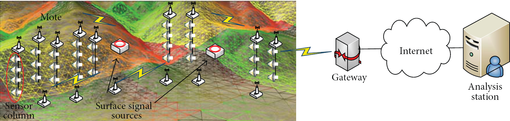
WSN based real-time landslide monitoring system.
Also, a structural health monitoring system of Golden Gate Bridge in San Francisco is designed and developed by UC Berkeley [23]. With collecting data from sensor nodes installed on the bridge, the system monitors ambient vibration of the structure. The sensor nodes have two types of accelerometer sensor and a thermometer sensor connected to a patch antenna, respectively; thus 59 nodes and 59 patch antennas are installed in the Golden Gate Bridge. 8 nodes of them have been arranged vertically and 51 nodes of them are placed with horizontal layout. Data are collected in PC station by wireless network provided by the patch antenna. The collected data are used to analyze the structural dynamic of the bridge by estimating its modal properties. Figure 3 shows the hardware block diagram of sensor nodes and their layout in the structural health monitoring of the Golden Gate Bridge. Most of these systems consist of a small-scale network or are connected to the sink node directly, so that their network expansion capability is a limitation. Also, these systems have used a self-designed sensor format and network.
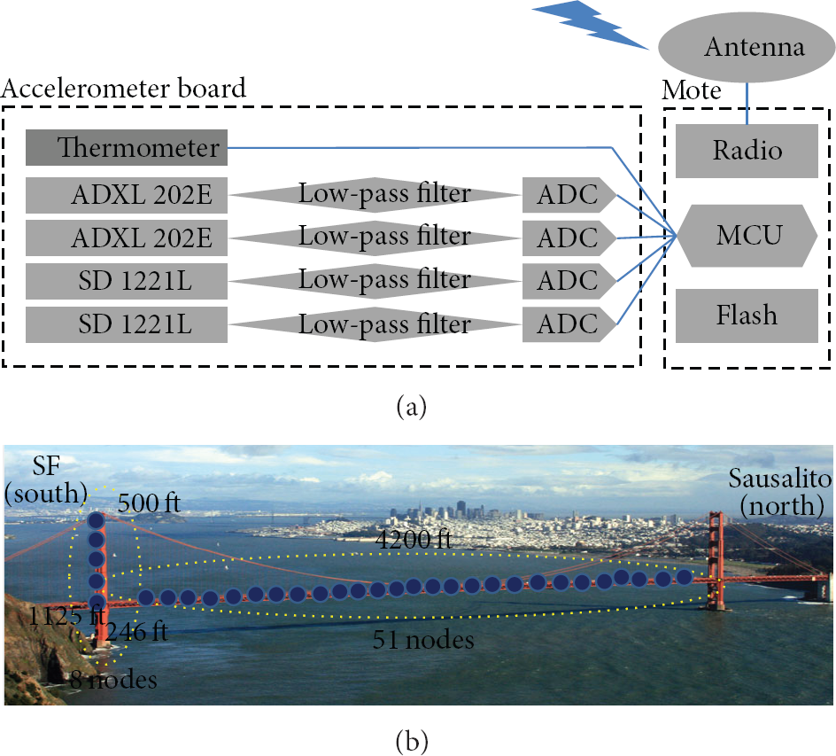
A structural health monitoring system of Golden Gate Bridge in San Francisco.
2.3. Issues on WSN Based Monitor System Integration
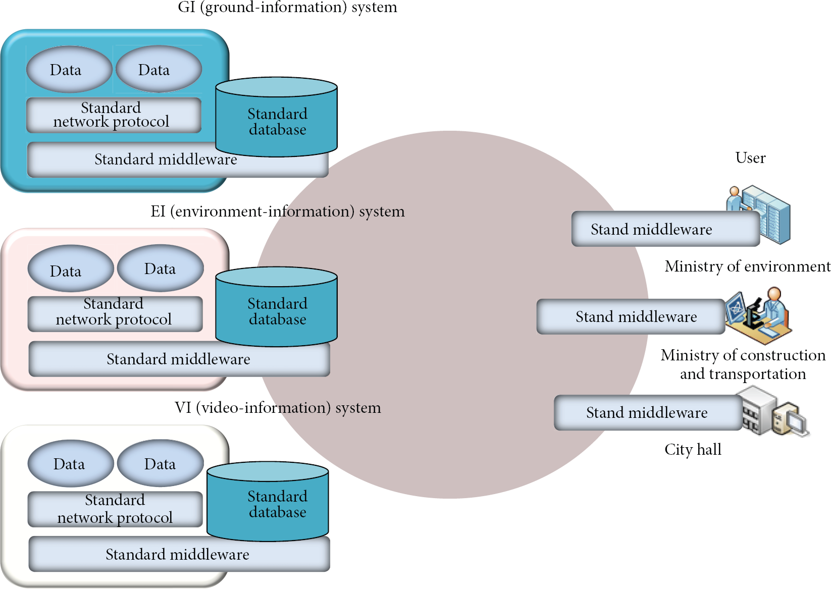
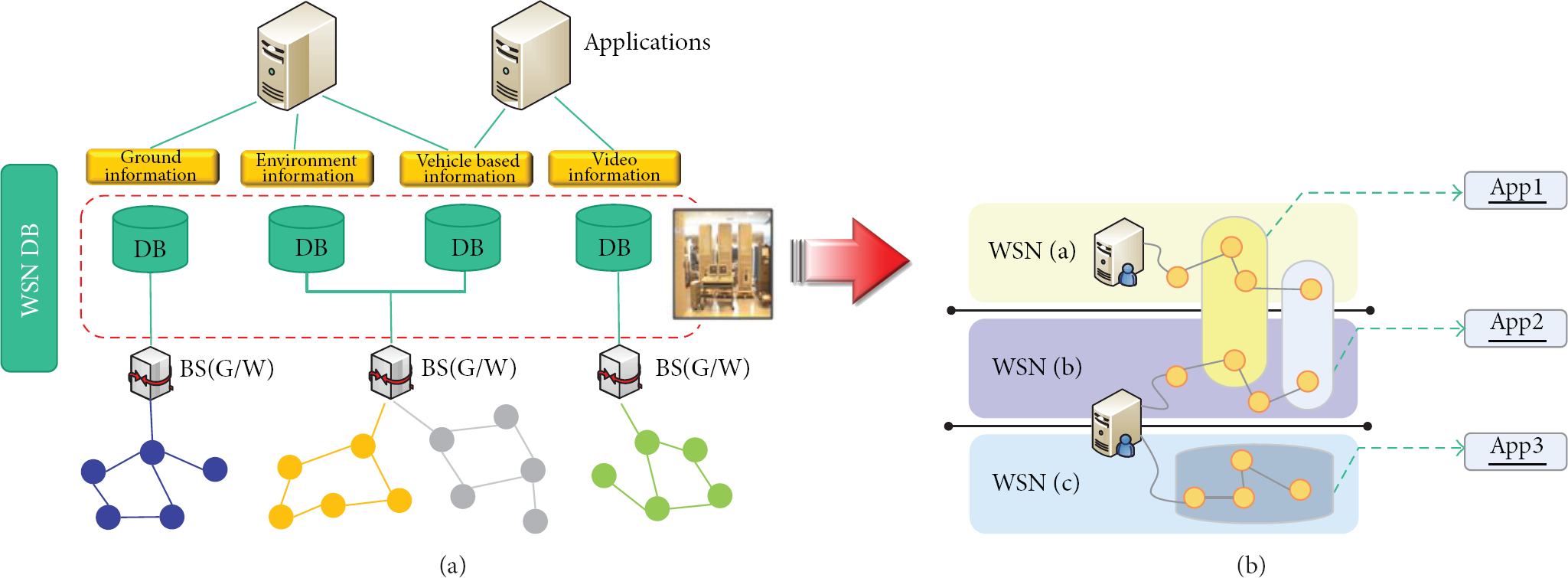
Various public organizations focus on constructing globally integrated monitoring systems and developing convergence technologies in order to deliver social security, organize national defense, ensure public safety, and respond to natural disaster rapidly. However, existing sensor networks generally operate as a proxy to deliver sensing data to the central monitoring system and use self-designed network protocols tailored to each application/service. Figure 4 shows an integration of traditional sensor networks. Since each system has its own network protocol/middleware/database, the integration middleware (Figure 4) is too complex and has many factors to consider, so that it can beget many potential problems. In other words, if we directly integrate heterogeneous proprietary protocols (GI system, EI system, and VI system described in Figure 4) into a single big system, the integrated monitoring system may cause a complexity of inner structure due to its own special purpose sensing format, query command, and so on. The integration system structure shall be kept updated upon adding yet another proprietary sensor network. Although many research efforts have been made to standardize the global network communication protocols over the Internet such as IP-WSN, the realization of seamless system integration cannot be achieved alone due to the lack of the fundamental standards in such aspects of sensing data format and database interfaces. We envisioned to design a simplified integration approach as presented in Figure 5. It can be achieved when standardized protocols are used on each WSN regardless of sensor network applications. As shown in Figure 5, by supporting that each system has a standard protocol/middleware/database and each application has a standard middleware, an integration of standardized sensor networks will be easier and scalability of this system will increase significantly.

Integration of traditional sensor networks.
Integration of standardized sensor networks.
2.4. Existing Works for Integration
SensorML (Sensor Model Language) specifies models and XML (Extensible Markup Language) encoding that provide a framework in which the geometric, dynamic, and observational characteristics of sensors and sensor systems can be defined [24]. This standard is derived from OGC (Open Geospatial Consortium) to access deployed web-enabled sensors in the field. Using SensorML, several models used for geographical location observation by deployed sensors are encoded as XML schema documents [25] and Algorithm 1 shows the example of represented simple data components. Both soft-typing and hard-typing of data parameters can be used in SensorML. For a soft-typed example, field name is defined and some description is included in the definition element. The code for unit of measurement and value for measured value elements is basically presented. The hard-typed example is similar to the soft-typed example. The main difference is that only field name is used in the soft-typed example. The measured value is presented as name, code, and value elements. Based on the defined metadata, common sensor information is encoded as XML. The data types, the data value, the unit of measurement, the value constraints to specify a variety of restrictions on the measured values, and the time value to be measured are included in each element. Recently, SensorML 2.0 was introduced to provide the IoT (Internet of Things) and WoT (Web of Things). As SensorML is encoded as XML, there are improved features, the extension using external schema, reasonable readability, and so on. This standard focuses on the geometric sensors and web-enabled sensors. Thus, relatively no lightweight sensors are utilized and an additional metadata is required to analyze the data. If an IP-based WSN is applied and lightweight and fixed sensors are deployed, these sensors can be tracked by using an IP address and data format can be required to reduce the processing delay and improve the performance.
<!—soft-typed –> <swe:field name=“fov”> <swe:Quantity definiton=“um:ogc:def:property:OGC:focalLength”> <swe:uom code=“mm”/> <swe:value> 0.1 </value> </swe:Quantity> </swe:field> <!—hard-typed –> <csm:fov> <swe:Quantity definition=“um:ogc:def:property:OGC:focalLength”> <swe:uom code=“mm”/> <swe:value> 0.1 </value> </swe:Quantity> </csm:fov>
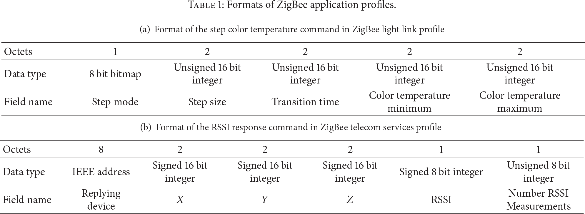
ZigBee [11] also specifies communication protocols and data formats on the ZigBee device [11]. It focuses on sensors with a low-power radio based on an IEEE 802.15.4 standard and has several application profiles that specify communication protocols and application data formats for each application. For instance, there are ZigBee Building Automation to monitor commercial building systems, ZigBee Health Care for healthcare services, ZigBee Home Automation to control appliances and lighting, and so on. Thus, the sensing data format is tightly coupled with each application profile. It means that delivered data format of sensors that has distinct application profiles is different although several sensors are implemented by ZigBee protocols. Table 1 shows two example formats of ZigBee Application Profiles. In this table, (a) denotes one command of ZigBee Light Link Profile. This command is delivered to allow the color temperature of a certain lamp [26]. Moreover, (b) also describes one command of ZigBee Telecom Services Profile. This command is responded when the RSSI request command is received. It has a location data and a RSSI value of a replying node [27]. As ZigBee standard is specified by several multi-national public companies, governmental groups, and so on, each application profile is defined by each primary member. Therefore, application profile data formats are different from each other generally, but they are based on ZigBee specification. Thus, all formats of profiles should be implemented without common data format. An improved data format with higher compatibility is required when several sensors are deployed in different networks.
Formats of ZigBee application profiles.
EPCIS (Electronic Product Code Information Service) [28] is an EPCglobal standard for the EPC to support the use of RFID (radio frequency identification) and the use of the Internet to share data via the EPCglobal Network [29]. Definitely, this specification involves a standard interface with captured and queried EPC data, appropriate security mechanisms, and related data standards. Moreover, it specifies the data definition for EPC data of simple sensors and RFID tags. The general contents of the data definition field have value types, event types, event fields, vocabulary types, master data attributes, and vocabulary elements. Its semantics are similar to SensorML and the contents are encoded as an XML schema. Using events delivered from readers, a UML diagram can be designed effectively and an event flow is mainly performed by defined protocols. Thus, focus is mainly not on the measurement data of deployed sensor nodes but the detection of events when a tag is exposed. The contents of deployed tags are generally fixed and limited, so they do not specify the data format of measured data. The acquired time information is covered with the data format at most. For this work, the XML schema such as SensorML and defined flow can be referenced.
3. Real-Time Global Monitoring Integration System
This section describes an overall system design for the real-time global monitoring and required components categorized by hardware and software.
3.1. IP-WSN Based Integration System
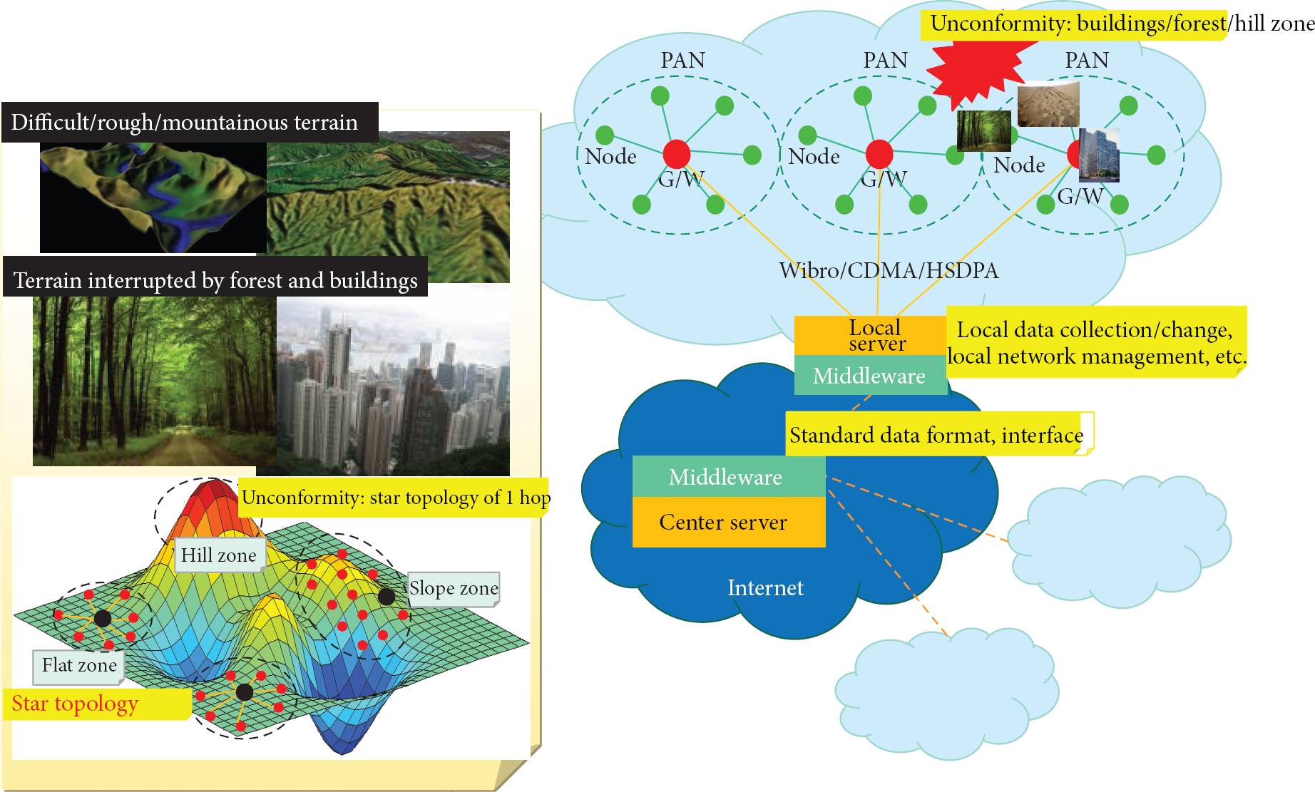
Figure 6 shows the real-time global monitoring integration system. The system consists of the ground/environment monitoring system, video collection system, and environmental monitoring system using ground mobility vehicles. The ground and environment monitoring system measures information on microseism, minute displacement, strain ratio, temperature, water level, water quality, exhaust/atmospheric gas, soil, and so forth for chief national facilities. A star topology may be used for a flatland including several types of farm fields and a multihop mesh topology is for trees, forests, hills, slanting surfaces, and winding areas. The 400 MHz band may be a better choice because of diffraction. The video collection system provides video information required for the global monitoring system in liaison with closed-circuit television (CCTV) systems built in a variety of public/private institutions. A star topology and peer-to-peer topology may be used for network cameras for the system. Also, it supports streaming services for real-time transport of video data and transformation services for streaming the types of existing CCTV videos. The environmental monitoring system using ground mobility vehicles monitors a wide scope of areas at runtime by compensating the limit of fixed monitoring systems using special purpose vehicles or public transportation equipped with mobile IP-WSN gateways and sensors. Its targets to monitor include road conditions, road materials, road information, facilities near roads, and information on the yellow dust. A star topology may be mainly used in/on a vehicle, but a tree topology may be more useful due to the limit of communication coverage caused by the deployment of sensor nodes inside/outside the vehicle. The 2.4 GHz band may be a good choice for this system.

An overall system designed for the real-time global monitoring.
The real-time global monitoring integration system works as follows. In the video collection system, network cameras communicate with each other via TCP/IP and a base station is connected to the Internet through LAN/WLAN, whereas other systems that deploy IP-WSNs and IP-WSN gateways may be connected to the Internet via a wireless communication medium (Wibro, HSDPA, CDMA, etc.) considering regional characteristics of their deployment. Information gathered from each system is managed by the local control system and it is stored in distributed databases in request to a query. The integrated control center manages those databases. The distributed databases can secure scalability, efficiency, and reliability since they logically integrate the databases which are distributed in multiple systems physically. For efficient management of system integration and national-scale network infrastructure, the network protocols may be standardized with IP-WSN for sensor networks and standardized Reader/Capture/Query interfaces may be applied for interoperation and integration of distributed databases and systems. In addition, standardized sensing data formats may be beneficial to unify existing territorial monitoring systems that have been operating separately. The system provides services facilitating integrated territorial information to government-related organizations, local governments, individuals, and so forth in close liaison with systems distributed throughout the country.
3.2. Systems Requirement
Figures 7 and 8 describe hardware and software architecture for sensor networks and video networks. The hardware architecture consists of database servers that collect and store sensing and video data by regional groups, backup database servers, control servers, GIS servers, and web servers. The integrated control system comprises the integrated database server to consolidate local databases, the integrated GIS server, and the integrated web server. The local control system also interoperates with the databases that belong to other regions. In Figure 7, sensor networks adopt an IP-WSN to fulfill a global WSN and techniques easily to interoperate with existing CCTVs may be standardized for better support of integrated monitoring. The software architecture shows software required for sensor networks and camera networks and for the integrated control system and local servers. Gateways and sensor nodes are necessary to build the sensor networks and gateways and network cameras are required to form camera networks. Moreover, the integrated control server, streaming servers, web servers, database servers, and GIS servers are necessary for the integrated control system and local servers. This software architecture of Figure 8 shows software required in two parts: integrated control server and sensor network including network camera. Integrated control server mainly uses desktop PCs and workstation PCs based on X86 and AMD, so that there is hardly a limitation on these kinds of software. That is, it is easy to implement, install, and use. Therefore, software blocks mentioned above are essential components for integrated monitoring. Sensor network, however, is different from integrated control flow. Because most of its hardware is embedded device based on ARM, MSP, and Atmel, its software has limitations. Specifically, software liveness is very important for seamless services. Also, additional software may be demanded because a variety of applications utilizing sensing data and video information from network cameras may appear in the future. Note that this paper proposes a guideline.

Hardware architecture for sensor networks and video networks.

Software architecture for sensor networks and video networks.
4. Integration Approaches for Existing WSNs
To build the real-time territorial monitoring system into which integrates existing WSNs at minimum cost, yet for maximum benefits, we propose WSN integration approaches that handle two main points where novel ideas for standardization are required. The least effort that existing WSNs should make is a use of standardized sensing data format regardless of their own network protocols. Moreover, how the system deals with collecting, sharing, processing, and accessing sensing data between WSNs and applications is another significant issue to solve. This section presents details that solve the two points.
4.1. Sensing Data Format
As for the first method to integrate existing WSNs, we propose a common sensing data format that all the WSNs should follow. That is, specific network protocols used in existing WSNs do not impact seriously on the system integration; rather, an actual sensing data format used in the protocols is a key since no matter what protocols are operated to deliver data anyhow, formats of the data to be utilized are the major difference among heterogeneous WSNs. The proposed format not only helps to integrate distinct data formats used in existing WSNs, but it also brings further benefits that will be discussed later.
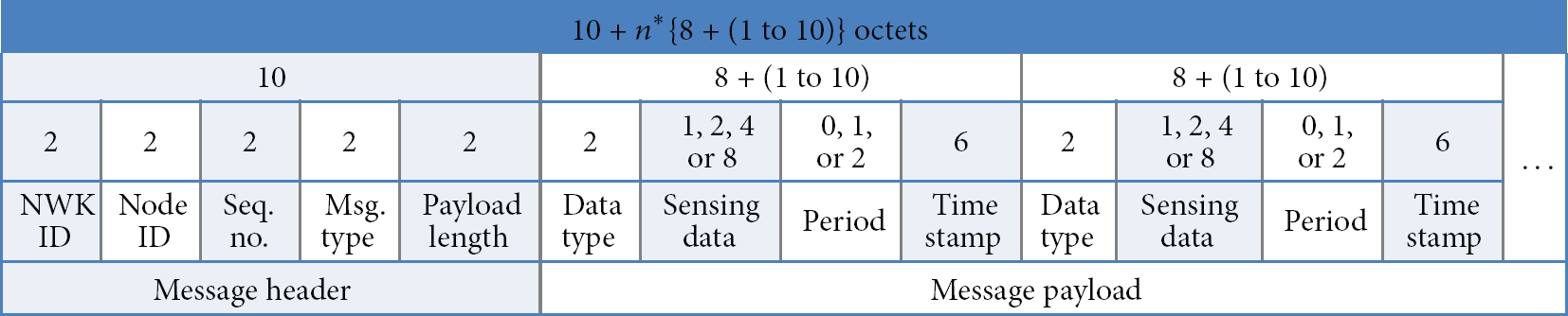
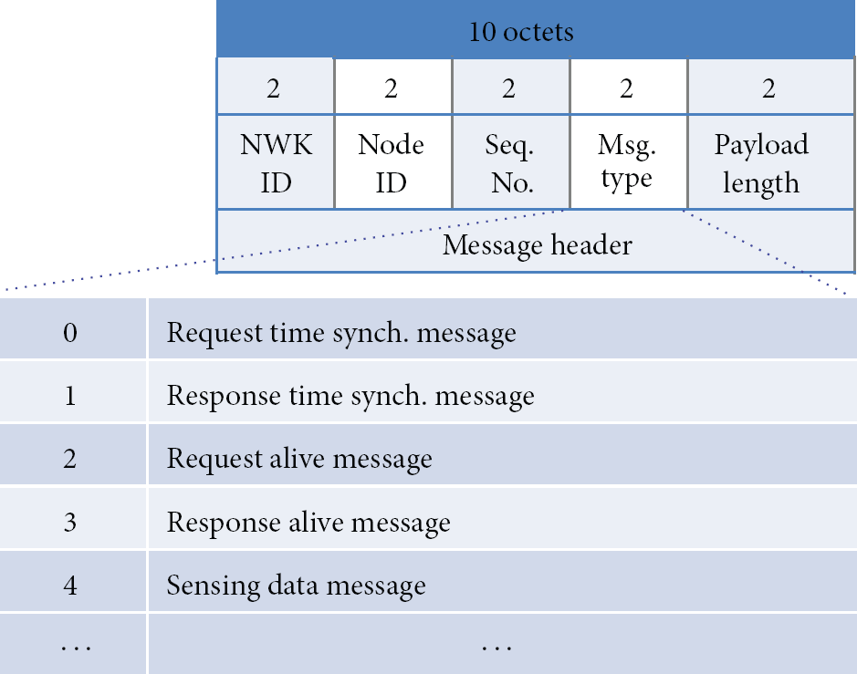
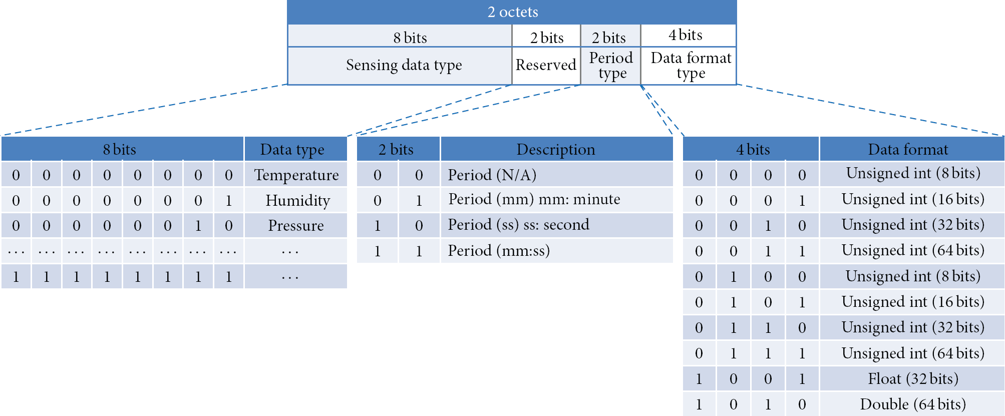
Due to unreliable characteristics of WSNs, we propose to use a UDP (User Datagram Protocol) packet on an IEEE 802.15.4 data frame. We assume that an IP-WSN is used for a network protocol; if another protocol is considered, only the available size for data is variable according to its frame format. As shown in Figure 9, the available size for Network Header and Data Payload that can be used in Frame Payload is 81 octets but Network Header can be compressed in accordance with RFC 4944. When sensor nodes communicate with each other within a single PAN (personal area network), UDP header fields, Version, Priority, Flow Level, Payload Length, Next Header, Source Address, and Destination Address, are compressible in Network Header in two octets shown in Figure 10. The size of Source Port, Destination Port, and Length in a UDP header can be minimized to 4 octets and data of maximum size 70 octets can be loaded. In case that a sensor node communicates with other networks outside a PAN, Source Address and Destination Address must specify a 128-bit IPv6 address. For such case, header compression is also available as the previous case except Source Address and Destination Address and data of size 54 octets can be included. The common sensing data format consists of a set of Message Header and Message Payload included in Data Payload after Network Header as depicted in Figure 11 in order to adjust the size of a variable message and to support rich data representation. A maximum of four sensing data per a packet can be loaded for communication with external networks and a maximum of six sensing data can be included for an internal network. As shown in Figure 12, Message Header is composed of Network ID (NWK ID), Node ID, Sequence Number (Seq. No.), Message Type (Msg. Type), and Payload Length to represent attributes of a real message, and Message Payload consists of Data Type, Sensing Data, Period, and Timestamp to express sensing data. Sequence Number in Message Header is to verify arrival of a message, and Network and Node ID are to identify networks and nodes to which the message belongs. Message Type distinguishes a type of a message used in a network. Figure 12 illustrates different types of messages that may be traversed in a network such as time synchronization messages, liveness messages, and actual sensing data messages. Payload Length stores the length of Message Payload. Actual sensing data are represented in Message Payload which includes four fields: Data Type to distinguish the type of sensing data, Sensing Data to present sensed values, Period to include a sensing period of the current sensor, and Timestamp to store measured time. As shown in Figure 13, the first octet of Data Type can express 256 types of sensing data such as temperature and humidity. Next two bits are reserved for future use and Period Type identifies one out of four period types: Period (N/A) meaning that a period type is omitted, Period (mm) indicating a unit of minute, Period (ss) for a unit of second, and Period (mm:ss) for a combination of minute and second. Data Format Type determines the data format from an 8-bit unsigned integer to a 64-bit double to support various types of sensing data that depend on applications.

UDP based on IEEE 802.15.4 data frame format.

Network head of UDP.
Message header and payload format.
Example of message header/types.
Data type in message payload.
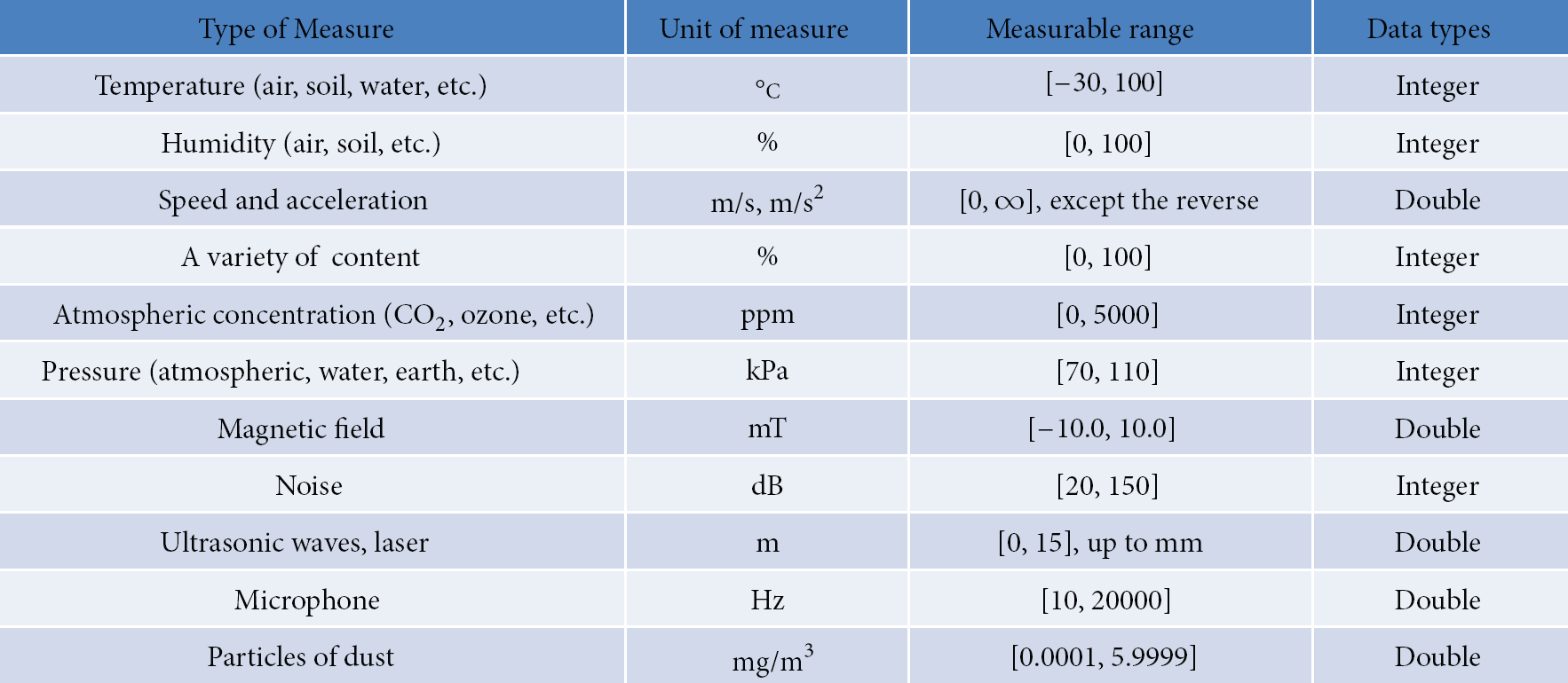
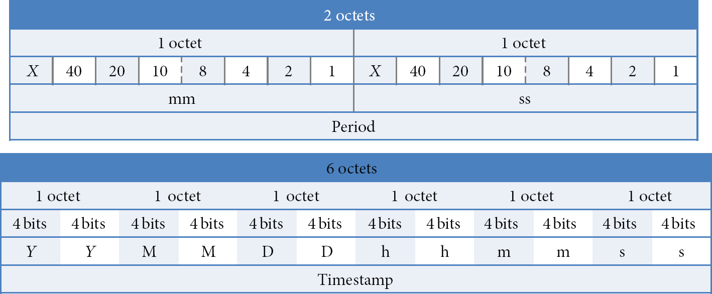
The size of the Sensing Data field in Message Payload is determined by the Data Format Type field in Figure 13. Also, the size of the Period field in Message Payload is set to 0, 1, or 2 octets by Period Type and the field stores BCD-coded time as shown in Figure 14. Likewise, the Timestamp field is also represented with a BCD code in YY:MM:DD:hh:mm:ss (Year:Month:Day:Hour:Minute:Second). This expression reflects characteristics of sensing data which are represented as either an integer or a real number and enables existing variable representations easily converted into specific sensing data representations. Although it depends on the type of sensors, most of representations of sensor information are applicable with the proposed representations. Moreover, if data representations are based on a standard and flexible data format within the range of defined data types as SI units (The International System of Units) shown in Figure 15, it is useful for heterogeneous WSNs to share sensing data compliant with a standardized fixed data format and for the integrated monitoring system to utilize the data systematically.
Period and timestamp.
SI units (the International System of Units).
4.2. Sensing Database
For the management of sensing data between WSNs and applications in an efficient and standardized way, we propose a novel method of database composition and a sharing model through a common interface in the middle. Figure 16(a) shows the overall architecture. Numerous types of sensing data collected from heterogeneous sensor networks via base stations or gateways are stored in databases independently constructed by individual monitoring systems. Those databases are integrated into the real-time territorial monitoring system and backup servers are also included in the system to secure the sensing data. The raw sensing data are processed into meaningful information for the individual systems and a variety of applications. In this process, our middleware architecture provides common interfaces specialized in functionalities of monitoring, sharing, and access. It, in turn, enables multiple applications to tailor the sensing data to their own purpose conveniently as depicted in Figure 16(b).
(a) Overall architecture. (b) Processed sensing data via the middleware.
The middleware provides common interfaces dedicated to monitoring and sharing of sensing data and access control between WSNs and applications. The idea of the common interfaces leads to standardization of three interfaces of the middleware so that they can be used by different monitoring systems and users in a seamless way. The middleware consists of Reader, Capture, and Query interface as shown in Figure 17 and each interface should be standardized since its unique functions are tightly related to operations of WSNs, databases, and applications.

Standard interface for sensing database.
The Reader interface is an interface that reads sensing data and events, and writes commands to cause WSNs to take particular actions from/to a base station or a gateway. Sensing data formats for numerous types of sensors used between the interface and WSNs should be defined with standardized formats described in the previous section. The Capture interface provides an interface that enables standardized access to databases and event registration/process, and subscription/publication of events. With these two interfaces between WSNs and databases, heterogeneous sensor networks can be integrated to the system transparently. Also, an XML/Web-based implementation is applicable to support higher-end applications. The Query interface resides between databases and applications and supports a message interface between the two domains. It exposes integrated query interfaces to applications so that each application can process its own set of sensing information for its specific purpose from databases.
5. Case Study for WSN Systems
This section describes network topologies to use in WSN systems and illustrates system deployment scenarios for a territorial monitoring system.
5.1. Network Topology
As shown in Figure 6, each monitoring system needs installation of sensor nodes and network configurations for various areas. We suggest network topology appropriate to surrounding environment and design the topology to construct an efficient system. For this, we summary main items to consider in network topology composition and study application scenarios of star, string, and mesh topology.
Firstly, star topology in which multisensor nodes are directly connected to one repeater has high-quality network reliability and this topology is normally one hop based to lower network overhead. That is, it is to show high transmission speed. Also, since development and installation are easy, not many high equipment such as network camera are suited for star topology. However, this topology has limitations of the number of node and network configuration/scope. For example, as installation area of sensor nodes is gradually becoming wider, the number of PAN increases and an exclusive gateway is additionally needed. Thus star topology is apt for a flatland with one-hop star pattern but is unfit for curved hills and places interrupted by building/wall/forest. Figure 18 illustrates a feature of star topology.
A feature of star topology.
Secondly, mesh topology with multihop keeps linking information between sensor nodes and is connected with other nodes. Because of this feature, when problems occur on the network, a new network configuration is created through other node's paths. So network scalability gets large and its coverage is wide. Beside star topology, mesh topology is relatively used in various and broad terrain (a flatland as well as places interrupted by hills, buildings, forest, and so on). Also, it can convert into other topologies such as tree topology by using dynamic address allocation and routing. However, network overhead increases due to multihop so that reliability is low and development/management is difficult relatively. With this weakness, multihop mesh routing is needed and power consumption can increase through forwarding technology of intermediate nodes. Figure 19 shows a feature of multihop mesh topology.

A feature of multihop mesh topology.
In case of network scenarios considering each topology, star topology is used in flatland, paddy, glebe, hill, and narrow area which can apply to one-hop pattern. And string topology applies to an area with straightness (e.g., railroad, stream, bridge, or road). Also, we have come to the conclusion that mesh topology is suitable for forest, hill, and interrupted/downtown area.
5.2. System Deployment Scenarios
Figure 20 shows a snapshot of the scenario for the territorial monitoring system designed for applicable regions. The scenario depicts the integrated control center, IP-WSN based monitoring systems, and a network camera system. The information of target point of interest is monitored by subsystems and collected to the control center, thereby providing various services at real-time such as web services and SMS. Also, it enables service users to cope immediately with emergency situations. The environmental monitoring system using ground mobility vehicles (Figure 20(1,2)) such as special purpose vehicles or public transportations sends information on the real-time volume of traffic, weather, exhaust gas, ozone, road conditions, and so forth over a drive. The location of the ground mobility vehicles is used to monitor the status of a specific region and deliver useful information to residents in vicinity of the area at runtime. The information is exchanged with the integrated control center via the mobile IP-WSN gateway installed inside the vehicles. The network camera system (Figure 20(4)) constantly monitors conditions of the volume of traffic, a parking lot, the status of environment, and so forth. For instance, cameras installed on a bridge observe the traffic on the bridge and water levels of a river at runtime in order to provide against emergencies. Furthermore, cameras in a parking lot monitor if there are empty spaces and notify drivers for ease of parking via the system. In addition, the system monitors (Figure 20(3)) tunnels and the ground at risk so that it can prevent disasters at early stage. The system should be time synchronized for real-time communication and measured sensing data should be delivered in standardized formats to servers in order to make use of interoperability. Moreover, each system takes a command from administrators to manage the update of sensing intervals, check the status of sensor nodes, change network protocols, and so on, thereby enabling organizational configuration and management. From this approach, we can build the real-time monitoring system that can manage the whole country through interoperation with major cities and regions as well as limited areas. Figure 20(6) indicates the central control center which integrates four IP-WSN systems and one video monitoring system.

Territorial monitoring system scenarios.
6. Feasibility Experimentation
For testing performance of IP-WSN suggested in this paper, a testbed system has been constructed in broadband integrated networks for development. An IP-WSN gateway is connected to KAIST default gateway through IPv6 optic switch and IP address to employ in PAN uses network prefix allocated from IPv6 network administrator. PAN coordinator is connected to the gateway with a serial cable and sensor nodes are connected with the coordinator using IEEE 802.15.4 wireless link. By doing this, PAN is formed. Using the testbed system mentioned above, we have measured and analyzed end-to-end transfer time of ICMP and UDP packets between IP-WSN sensor networks based on IPv6 and remote host of external IPv4. This experimentation is to show interoperability related to system integration suggested in this paper.
30 sensor nodes are deployed at 10-meter intervals in an open area without obstacle and one PAN is created. Routing protocol uses HiLow and we redefine its values (the maximum number of child nodes per parent node: 2, network depth: 5). For testing ICMPv6, send_buffer_size of ping6 is 0 because of not implementing fragmentation and reassembly. For testing a UDP, we install UDP client program written JAVA on a remote host and a UDP server program written C on sensor nodes. We send 61-byte ICMPv6 packets and 63-byte UDP packets 50 times from the remote host to sensor nodes and measure round-trip time as millisecond unit. Figure 21 is given to show an average round-trip time of ICMPv6 and UDP packets according to number of hops. y-axis value corresponding to 0 of x-axis means round-trip time from a remote host to a PAN coordinator. As shown in this figure, Avg. round trip time (ping and UDP) increases as the number of hops increases. It means that intermediate nodes to transfer packets to destination have cumulative packet processing time by hop and there exists transfer delay time of wireless link in all nodes. Round-trip of UDP packet takes approximately 50 ms by comparison with ICMPv6. The reason is that processing time can differ because of more UDP packet located above ICMP packet on network stack than length difference of transferred packet. Therefore, given interoperability of IPv4 and IPv6, we should consider this experimental result.
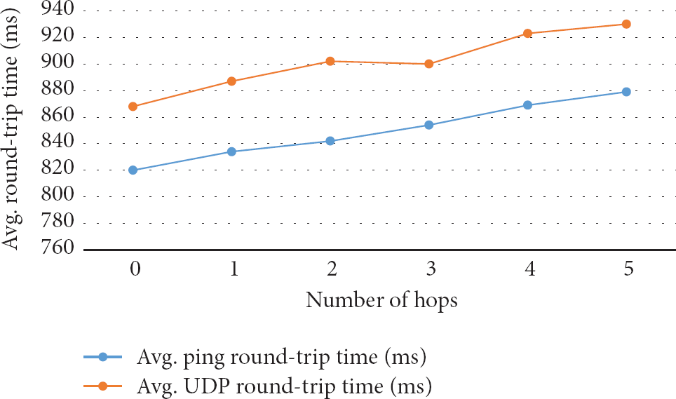
Round-trip time of ICMPv6 and UDP packets.
7. Conclusion
We present a global integration avenue of ground monitoring based on WSNs. For this, an overall system is designed for the real-time global monitoring and we classify components requiring in the system by hardware and software. Designed system is IP-WSN based real-time global monitoring system to ensure compatibility and interoperability among various WSN systems. This system focuses on territorial monitoring: territorial ground/environment and inner cities including downtown areas. For unstrained integration, sensing data formats and their database interfaces are suggested. Therefore, this enables a spontaneous and systematic integration among the legacy WSN systems to construct efficient and effective territorial monitoring systems. We categorize network topology according to topographic characteristics and the topology can help deploy sensor nodes on real world, so that we envision that the proposed technology would be an essential element for the practically deployable global territorial monitoring systems. In the future, we plan to construct an IP-WSN based testbed system using an integration avenue of WSN systems for real-time global monitoring.