
Abstract
A surface panel method for a boundary-value problem with the free surface is proposed to predict ship wave resistance under different trim conditions based on a so-called double-model solution. The free surface boundary condition is linearized with respect to the oncoming flow and computed by a four-point finite difference scheme. Sample computation for Wigley hull is carried out to demonstrate the effectiveness and the robustness of the method. A hull model is taken into account at two different displacements with respect to trim conditions of lower wave resistance. It is demonstrated by calculation and experiment that the wave resistance under the trim conditions provided by the proposed method is lower than that under the initial conditions.
1. Introduction
With respect to green shipping, the main challenge for the hydrodynamics community is to help reduce the ship resistance. Ship resistance has often been taken into account by employing excellent hull forms or hull lines optimization in ship design stage [1–3]. Another option to optimize the resistance of ships without modifying the vessel is to consider the operational efficiency of the hull, including the trim operation. For each draft and speed, there is a resistance-optimum trim [4]. For ships with large transom sterns and bulbous bows, the power requirements for the best and worst trim may differ by more than 10% [5]. Model tests or CFD simulations have been used to assess the best trim and the effect of different trim conditions [6, 7]. However, model tests are too costly and further efforts are required to improve the reliability and effectiveness of CFD simulations. In this paper, a new method is developed to explore better trim conditions for a certain hull with typical wave making being taken into account.
For simulating wave resistance problems in potential flow codes, the Rankine source method is considered as the most widely used technique [8, 9]. A method for verifying a critical aspect of numerical prediction of fully nonlinear free-surface flow around ship hulls steadily advancing in calm water is given by [10] Noblesse et al. Tarafder and Suzuki [11, 12] developed a potential-based boundary element method to investigate the influence of the water depth and the wave interference effects on the first- and second-order wave resistance of a catamaran hull. At the same time, a surface panel method treating a boundary-value problem of the Dirichlet type with free surface was presented to design a three-dimensional body by Yoo [13]. The free surface boundary condition was linearized with respect to the oncoming flow and computed by four-point finite difference scheme.
Details of waves, such as patterns and profiles, are usually used to assess the reliability of numerical methods. Tarafder and Khalil [14] extended Morino's panel method for the calculation of wave resistance of ships with special reference to sinkage and trim. The method had been applied to the Series 60 hull and was found to be efficient for evaluating the flow field, wave patterns, and wave resistance in deep water. Yang and Löhner [15] extended a parallel free-surface flow solver to account for sinkage and trim effects in the calculation of steady ship waves, using a finite element method. The computed wave profiles and wave drag were in good agreement with experimental measurements and observations for two hull forms at a wide range of Froude numbers. Zhang et al. [16] proposed an optimization design method to obtain a hull form with the minimum wave resistance, combining the Rankine source method with the nonlinear programming. S60 hull form was selected as the original hull for optimization design, and the Rankine source method was proved to be an effective method in ship wave optimization.
The aim of this paper is to optimize ship trim conditions to reduce wave resistance by applying a potential-based boundary element method [17]. An upstream finite difference operator [18] is used to satisfy the radiation condition, and the free surface as well as the wave resistance is determined by an iterative algorithm. The Wigley hull is used as an example to verify the method by comparing wave resistance and the details of wave profiles. Finally, numerical calculations are taken to optimize the trim condition for a certain container carrier called HUST hull (hull of Huazhong University of Science and Technology), and comparative model tests are conducted to assess the practicality of the method.
2. Statement of the Problem
Consider a ship moving with a constant speed U in calm water. A ship-fixed Cartesian coordinate system oxyz is defined with origin o located at the midship on the calm water surface. The x-axis is positive towards the ship stern, the y-axis positive to starboards and the z-axis positive upwards (Figure 1).

Definition sketch of the coordinate system.
It is assumed that the fluid is incompressible and inviscid and the flow is irrotational. The total velocity potential ϕ can be expressed as a sum of the double-body velocity potential ϕ H and the perturbed wave potential ϕ F ; that is,

The velocity potentials ϕ H and ϕ F are expressed as


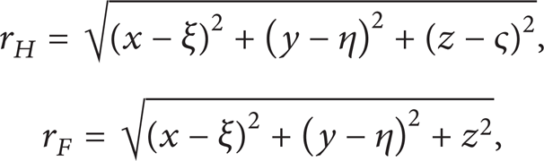
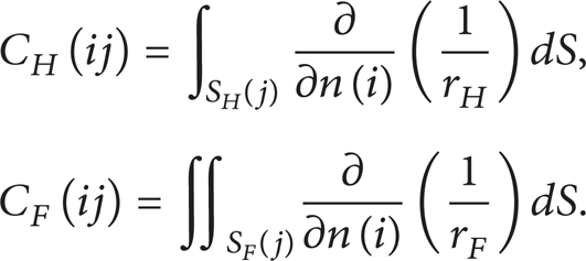
where S H is the hull surface of the double-body and S F is the undisturbed free surface. σ H , Δσ H , and σ F denote source distributions on double model surface, ship surface, and free surface, respectively. r B and r F denote the distances to field point (x, y, z) from source points (ξ, η, ς) and (ξ, η, 0), respectively.
And then the motion of the flow can be uniquely defined by imposing the boundary condition on the boundary surface as follows.
Hull boundary condition is as follows:

where
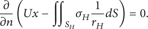
Linearized free surface boundary condition can be simplified as [18]

where the subscript denotes the differentiation along a streamline on the symmetry panel z = 0.
In addition, a four-point finite upstream scheme is used to ensure that the free-surface waves vanish upstream of the disturbance.
Substituting (2) into (5), we get
The double-body hull surface S H is discretized into a number of N H panels. Equation (7) at the ith panel becomes
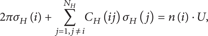
where
Then ϕ F l in (6) can be expressed as

After discretizing S F into a number of N F panels, we get

where

where e n is a four-point upstream finite difference operator, which can be calculated by a method of undetermined coefficients.
The vertical velocity component ϕ F z on the free surface can be written as

Substituting (3) into (5), equations about Δσ H and σ F can be simplified as
where i = 1, …, N H ,
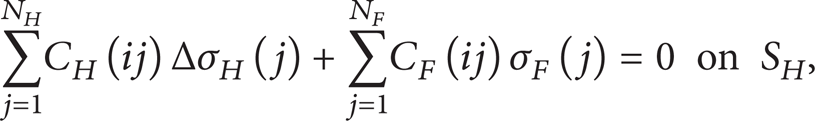
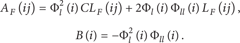
Substituting (10) and (12) into (6), equations about Δσ H and σ F can be simplified as

where i = N H + 1, …, N H + N F ,

An iterative method is used to obtain the solution of (13) and (15). The source distribution Δσ H can be firstly approximated as Δσ H (1) = 0. After substituting Δσ H (1) = 0 into (15), we can get the first approximation of σ F , that is, σ F (1). The solution σ F (1) is substituted into (13) to get the second approximation of Δσ H , that is, Δσ H (2). This procedure is repeated until (13) and (15) are satisfied to a given error tolerance. The iteration numbers are about 5∼10 in this study for a certain tolerance of ∊ = 1.0 × 10⁻⁶ in the present program procedure.
The wave resistance coefficient is expressed as

where S is the wetted surface area of the hull in calm water, ρ is the water density, ΔS i is the area of the panel element, n xi is x-component of the unit vector normal to the surface panel element, and C p is the pressure coefficient determined by Bernoulli's equation.
The wave profile can be expressed as

where g is the acceleration of gravity.
3. Sample Calculation
The well-known Wigley hull model is first used to check the accuracy of the numerical procedure. Lines function of the hull can be written as
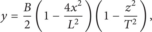
where L, B, and, T are the length, breadth, and draft of the ship, respectively, in calm water. The characteristic dimensions of the Wigley hull are B/L = 0.1, T/L = 0.0625, and C B = 0.444. Half of the hull surface is discretized by 40 × 8 quadrilateral panels and a free surface domain (−1 ≤ x/L ≤ 2 and 0 ≤ y/L ≤ 1) by 100 × 20 panels.
The Wigley hull is calculated with fixed trim and sinkage, and the computed wave resistance coefficient is consistent with experimental and numerical results reported in another study [19], as shown in Figure 2. Figure 3 shows the numerical and experimental results on wave profiles along the body surface at Fn = 0.316. They agree well with each other, and the present results are more accurate than those got from Tarafder and Suzuki [19]. It can be argued that the numerical method and program procedure conducted in the paper are feasible based on the comparisons on the wave resistance and wave profiles of the Wigley hull.

Comparison of wave resistance of Wigley hull.

Wave profiles of the Wigley hull at Fn = 0.316.
A certain type of ship called HUST hull (hull of Huazhong University of Science and Technology) of which the principles are specified in Table 1 is used to conduct trim optimization in which wave resistance is selected as the objective function. The design variable is trim condition defined by drafts at bow and stern of the hull (expressed as T f and T a resp.). The trim and the sinkage are fixed at each iteration and the displacement is kept constant during the optimization. Two cases of the HUST hull with different displacements are taken into account. Half of the hull surface is discretized by 50 × 8 quadrilateral panels and a free surface domain (−1 ≤ x/L ≤ 2 and 0 ≤ y/L ≤ 1) by 130 × 20 panels, as shown in Figures 4 and 5.
Main particulars of the HUST hull.


Typical panel arrangement for the hull.

Typical panel arrangement for the free surface.
The optimization procedures in which wave resistance and wave profiles are calculated are performed in a range of 0.15 ≤ Fn ≤ 0.26. Both cases are optimized with an initial trim condition of the even keel (T f = T a ). The optimization results of the two cases are as follows.
Case 1 (∇ = 0.7136 m3, C B = 0.7433).
Consider the following:
initial trim condition: T f = 268.69 mm, T a = 268.69 mm, and trim = 0;
trim condition 1: T f = 243.57 mm, T a = 293.17 mm, and trim = – 49.60 mm;
trim condition 2: T f = 223.26 mm, T a = 310.76 mm, and trim = – 87.50 mm.
Case 2 (∇ = 0.7969 m3, C B = 0.7589).
Consider the following:
initial trim condition: T f = 294.83 mm, T a = 294.83 mm, and trim = 0;
trim condition 1: T f = 303.14 mm, T a = 286.14 mm, and trim = 17.0 mm;
trim condition 2: T f = 285.08 mm, T a = 304.58 mm, and trim = – 19.5 mm.
Wave profiles of different trim conditions of Case 1 are shown in Figure 6, where the wave heights of both trim = – 87.50 mm and trim = – 49.60 mm near the hull are lower than those of the initial trim condition. Wave patterns of the three trim conditions for Case 1 are shown in Figures 7, 8, and 9, respectively, in which one can find that the wave-making heights and patterns vary as the bulb bow comes to penetrate the free surface.

Wave profiles of the HUST hull at Fn = 0.217 (Case 1).

Wave patterns around HUST hull at Fn = 0.217 (Case 1, trim = 0).

Wave patterns around HUST hull at Fn = 0.217 (Case 1, trim = −49.6).
Wave patterns around HUST hull at Fn = 0.217 (Case 1, trim = −87.5).
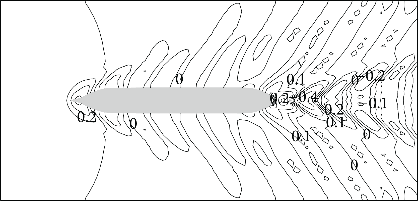
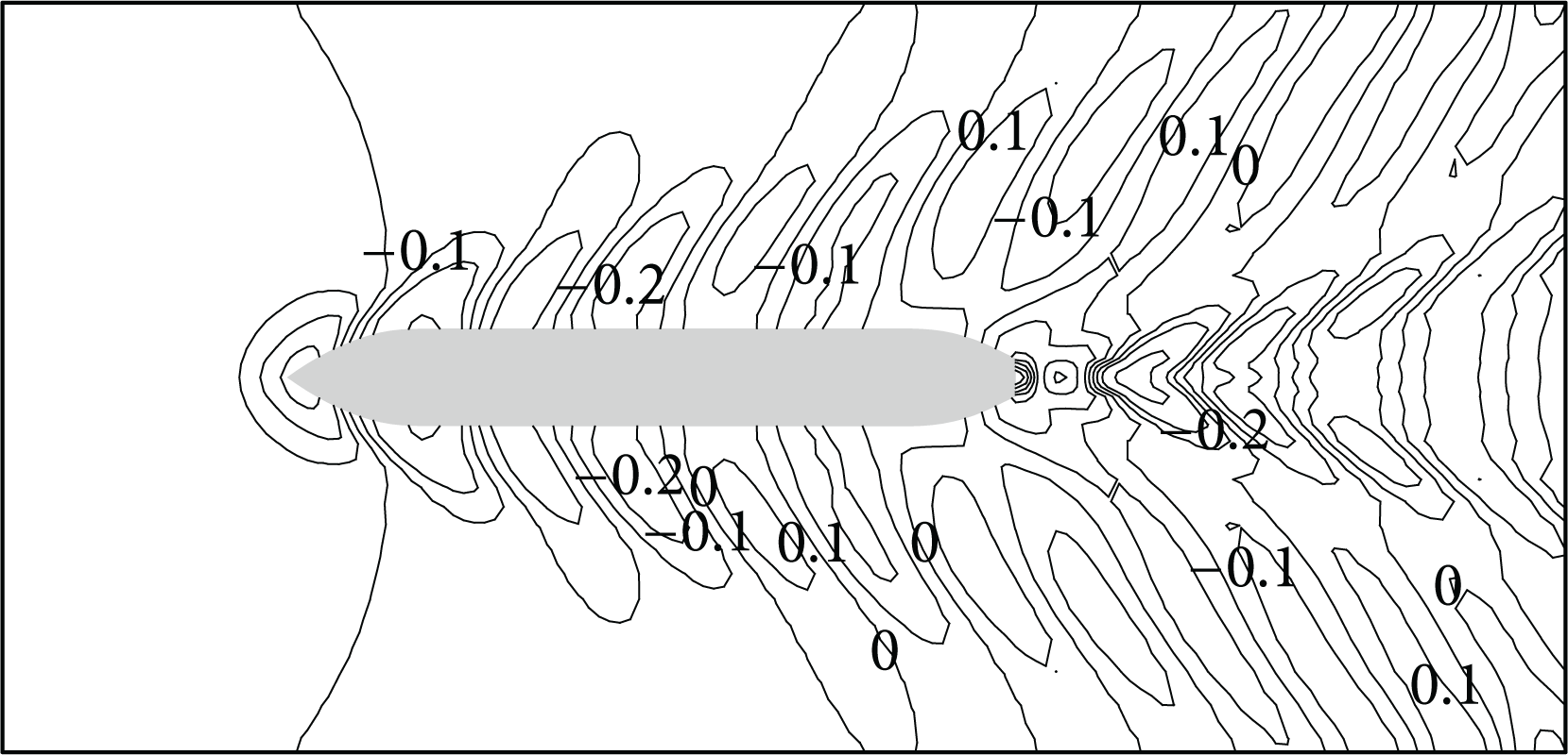
Wave profiles are shown in Figure 10 and wave patterns are shown in Figures 11, 12, and 13 for Case 2. Though the wave patterns change of different trim conditions is not as significant as that observed in Case 1, a better trim condition (trim = 17.0 mm) of lower wave heights can be found from the wave profiles along the hull surface.

Wave profiles of the HUST hull at Fn = 0.217 (Case 2).

Wave patterns around HUST hull at Fn = 0.217 (Case 2, trim=0).
Wave patterns around HUST hull at Fn = 0.217 (Case 2, trim=17.0).

Wave patterns around HUST hull at Fn = 0.217 (Case 2, trim = −19.5).
Model tests are performed in the towing tank of Huazhong University of Science and Technology to assess the practicality of the numerical method and optimization procedure. The wave resistance under the initial trim condition and the optimized one is compared numerically and by experiment as shown in Figures 14 and 15.

Wave resistance of HUST hull (Case 1).

Wave resistance of HUST hull (Case 2).
For Case 1, as shown in Figure 14, the numerical results show good agreement with the experimental results at a wide range of Froude number under most trim conditions. In addition, the variation tendency of calculated wave resistance under different trim conditions is almost the same with that of model tests when Fn > 0.21. In particular, under both optimized conditions of trim = – 49.6 mm and trim = – 87.5 mm, excellent wave-making performance is observed at the design speed (Vs = 16 kn, Fn = 0.217) in both numerical calculation and experiment. For Case 2, despite the imperfect agreement between numerical and experimental results, the agreement of variation tendency shown in a scope of 0.2 < Fn < 0.23 is quite satisfactory. As shown in Figure 14, the resistance under the condition of trim = – 19.5 mm is higher than that of the initial condition, while that under the condition of trim = 17.0 mm is lower.
4. Conclusion
For the purpose of reducing the wave-making resistance, a surface panel method involving linearized free surface condition and double model solution proposed by Dawson is developed to optimize ship trim condition. After being verified by the Wigley hull calculation, the method is applied to optimize trim condition of the HUST hull, and the wave resistance is used as the objective function. Calculation results show that the proposed numerical method could be a practical tool for wave resistance prediction for some hull forms under certain trim and displacement conditions. For the Wigley hull, the wave resistance and the wave profiles of the present calculation agree well with those obtained from experiments. However, the numerical results and the experimental results of wave resistance show agreement of different degrees at different displacements for the HUST hull. Under the modified trim conditions, the wave resistance of both cases of the HUST hull is lower than that under the initial condition according to calculation and experiments. Therefore, the method is considered a practical approach to ship trim operation for energy saving.