
Abstract
Geometrical, physical, and electrical parameters have influences on the precision of printed circuit board Rogowski coils (PCBRCs). This paper outlined operating principles and properties of PCBRCs. Two kinds of positional sensitivities between current conductor and PCBRC are analyzed, and mathematical models and formulas for error computing are established and derived. The roles of some critical geometrical parameters are characterized and verified by experiment. These methods can be used to define structure parameters of PCBRC for precise current measurement applications.
1. Introduction
Rogowski coil (RC) is a kind of helical coil used for electric current measurement. Unlike other current transformers using an iron core as the former, the wire of RC is wound on a nonmagnetic core like bakelite, glass, plastic, or rubber and so on. Therefore, RCs do not suffer from magnetic saturation effects and operate linearly. Many of the useful features result from this linearity. (1) They have excellent capability to measure currents in a very wide range from a few milliamperes to several million amperes. (2) They have a very wide bandwidth, extended from 0.1 Hz to 1 GHz, which enables them to measure or reproduce the waveform of rapidly changing currents or small-duration pulsed currents. (3) They have no direct electrical connection to the main circuit. This provides galvanic insulation and produces no heating, allowing them to measure currents nonintrusively and safely. (4) They can be designed flexibly and lightweight, making a very useful contribution to the art of measuring currents under various circumstances, particularly where high currents are involved. These advantages are rapidly generating interest in various applications, namely, power quality monitoring, relay protection, power electronic converter monitoring, large magnitude AC current measuring, pulsed current measuring, and high frequency current measuring [1–9].
From the point of view of the manufacture process, practical RCs can be classified into wire-wound RC [6], machinable RC [7], and printed circuit board Rogowski Coil (PCBRC) [8–10]. Different kinds of the manufacture offer RCs with different properties. PCBRCs show advantages in uniformity over wire-wound coils and are suitable to be used in precise metering of AC current. In this paper, the operating principle of PCBRC is presented, and the error analyses under two different position conditions are performed.
2. Principles of Operation
2.1. Ideal Rogowski Coil
The operating principle of an RC can be illustrated by Faraday's law of induction, together with Ampere's circuital law. Figure 1 shows a long and thin RC, with the winding-distributed density of n turns per meter and the cross-sectional area A, which encircles a conductor carrying a current i(t) following a closed curve of arbitrary shape [6].

Model of an ideal RC.
In a small section of length dl along the loop, the number of turns is ndl, and the flux linking the section is

where H is the magnetic field and α is the angle between the direction of the field and the direction of the section. The magnetic flux linking the entire coil is given by integrating along the loop l:
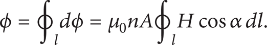
From Ampere's law, if a curve is drawn in a loop which totally encircles the current, then the line integral of the magnetic field around the loop is equal to the net current enclosed by it no matter what path the loop takes. Mathematically, this is expressed as

From Faraday's law, for an AC current, the induced electromotive force e output from the coil is

where di/dt is the rate of change of the current enclosed by the closed curve. The term μ0nA is often called coil sensitivity or mutual inductance in terms of M, where M = μ0nA.
Therefore, for an ideal RC, its output voltage is proportional to the rate of change of measured current and is independent of the external currents/fields, as well as the path taken by the loop and the conductor location inside the coil loop. This makes RC ideal for AC current measurement.
However, to follow Ampere's law well, it requires the following. (1) Uniformity: the winding must be wound with a constant number of turns per unit length on a former of uniform cross-sectional area. With a flexible coil, the winding must remain uniform when the coil is bent; (2) small cross-sectional area: it means that the radius of cross-section of the coil is much less than the distance from the coil to the current conductor provided that it is circular; (3) the value of winding-distributed density is large, so the helix may be approximated by a large number of evenly spaced turns that are each normal to the curved axis of the helix [11].
2.2. Printed Circuit Board Rogowski Coil
Accurate CAD design methods and advanced PCB manufacturing technology, as well as the limitations of material and technique, provide PCBRC distinctive characters: (1) they have a very uniform turns distribution and a highlyuniform cross-sectional area over other wire-wound Rogowski coils and are more approximated to an ideal one; (2) they have a relative larger ratio of outer radius to inner radius against wire-wound coils and are far from an ideal one; (3) the value of winding-distributed density is smaller than those of wire-wound ones and under the expected condition to be an ideal one; and (4) a lower value of self-inductance in comparison with wire-wound coils and the response of the coil and the bandwidth are improved. In a word, PCBRC shows character of discreteness and differs from an ideal RC and wound-wire ones to some extent.
We present a kind of practical PCBRC in [10], as shown in Figure 2. In an ideal situation, the primary conductor is set exactly on the center of a PCBRC coil. The inner and outer radii of the coil are marked as r a and r b , respectively; the width of the coil is marked as h.
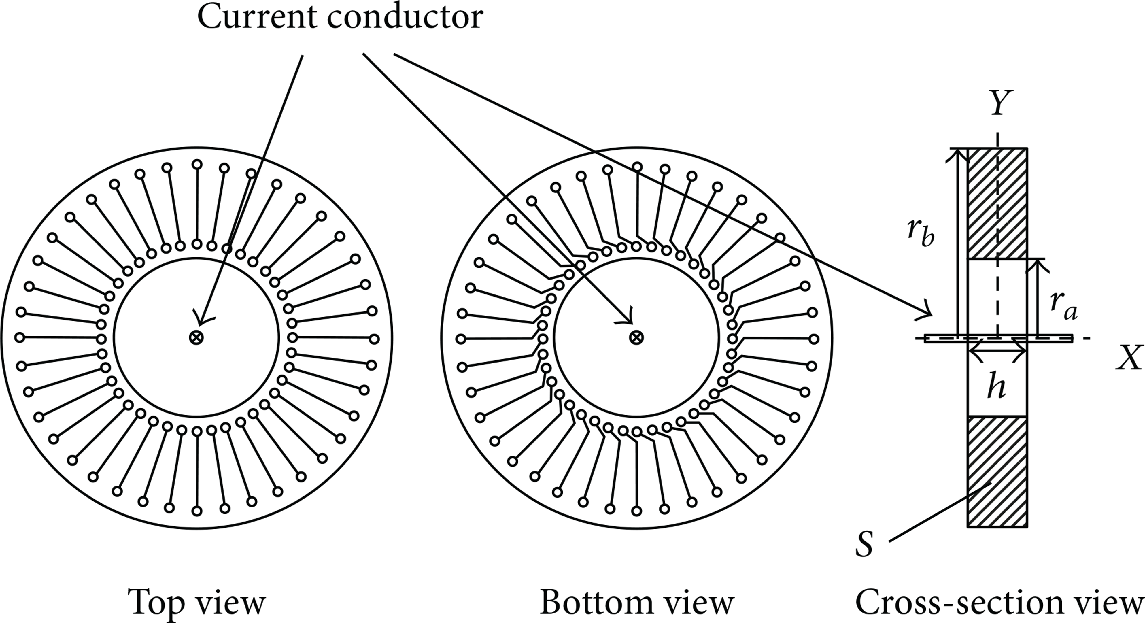
Setup of a PCBRC.
From Biot-Savart law, the magnetic field B induced by the conductor current i is given by

where μ0 is the magnetic constant and r is the distance between the center of the conductor and the location at which the magnetic field is being calculated.
The magnetic flux through the cross-section of a single turn is defined as the integral of the magnetic field over the area of cross-section S in the coordination system shown in Figure 5:

Considering that PCBRC has a uniform cross-sectional area and a constant distribution of turns, the total flux linkage by the coil can be written as a sum over individual turns rather than an integral:
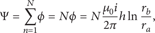
where N is the number of turns of the coil.
Consequently, the electromotive force e induced in the coil by the current is

where M = (μ0Nh/2π)ln(r b /r a ) is the mutual inductance.
Conclusions can be made that, for a PCBRC under ideal condition, its output voltage is proportional to the rate of change of measured current provided that M keeps constant, just like an ideal RC.
3. Error Analysis
Under practical conditions, the measurement accuracy for most of actual RCs depends on geometrical, physical, and electrical influences [10–13]. The influence of the position of current conductor relative to PCBRC is taken into account in this paper. The consideration is divided into two partial cases. The first is the case when the current conductor is not placed at the center of the coil but at a distance from it, with the axe of current conductor and the axial axe of PCBRC keeping parallel. The second is the situation when the conductor is centered, but its axe exhibits an angle relative to the axial axe of the coil. Both situations will be considered in the following analysis.
3.1. Eccentric Position Error Analysis
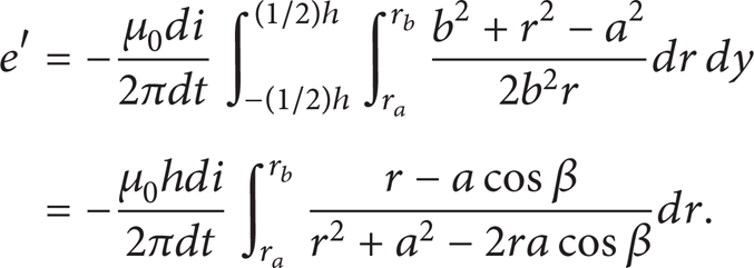
To calculate the electromotive force e′ induced in one turn, the differential of magnetic flux can be used with one exception. The force is affected only by the normal component Bcosα of the field, rather than the whole field B, which is shown in Figure 3. Provided that a is the eccentric distance between the conductor and center point O, the induced electromotive force by the turn encircling point A is

If we denote that

the electromotive force will be
Defining ratio factor κ = r b /r a and eccentric factor σ = a/r a , the expression (11) can be rewritten as
As mentioned previously, a practical PCBRC has a distribution of discrete character instead of a continuous one. The actual total electromotive force e is calculated as a sum over all individual turns rather than an integral:

Define eccentric error δ(σ) as

The presented theoretical analysis and simulated calculation of eccentric error, as shown in Figure 4, indicate the following. (1) Larger number of turns could cause a smaller measurement error. The error could reduce below 0.005% when the number of turns reaches 500. (2) The error depends on eccentric factor. It could be reduced by decreasing σ and be lower than 0.01% when σ is below 0.6 (as N = 200 and κ = 1.01). (3) This error also depends on ratio factor. It could obviously decline from approximately 0.15% for κ = 1.01 to lower than 0.01% for κ = 3 (as N = 200 and σ = 0.98).

Geometrical diagram for eccentric error analysis.

Calculated eccentric error: (a) PCBRC with 200 turns; (b) PCBRC with 500 turns.

Geometrical diagram for tilting error analysis.
3.2. Tilting Position Error Analysis
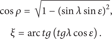
Theoretical consideration has been done with the presumption that the current conductor is still in the center of the coil (point O) with an angle λ to the axial axe OY in the plane of XOY as it is shown in Figure 5. To examine the flux at the point B in the plane that is rotated for angle ∊, we need to observe the projection of the current conductor on that rotated plane. The method presented in [13] is adopted here. The geometrical relation of this projection is illustrated in Figure 6.

Geometrical relation of the projection.
From the described situation, the relation can be written as
To examine the dependence of the enclosed flux due to the angle λ, we will observe the projection of the conductor on the presented plane, which is shown in Figure 7.

Projection of primary conductor on the plane rotated for angle ∊.
Here, it is obvious that the calculation of the magnetic flux for the turn enclosed B can be divided into three influencing areas: the first one (I), which is the closest to the conductor and forms triangle, the second one (II) that has a form of parallelogram, and the third one (III), which is the furthest triangle from the conductor. These areas are marked in Figure 8.
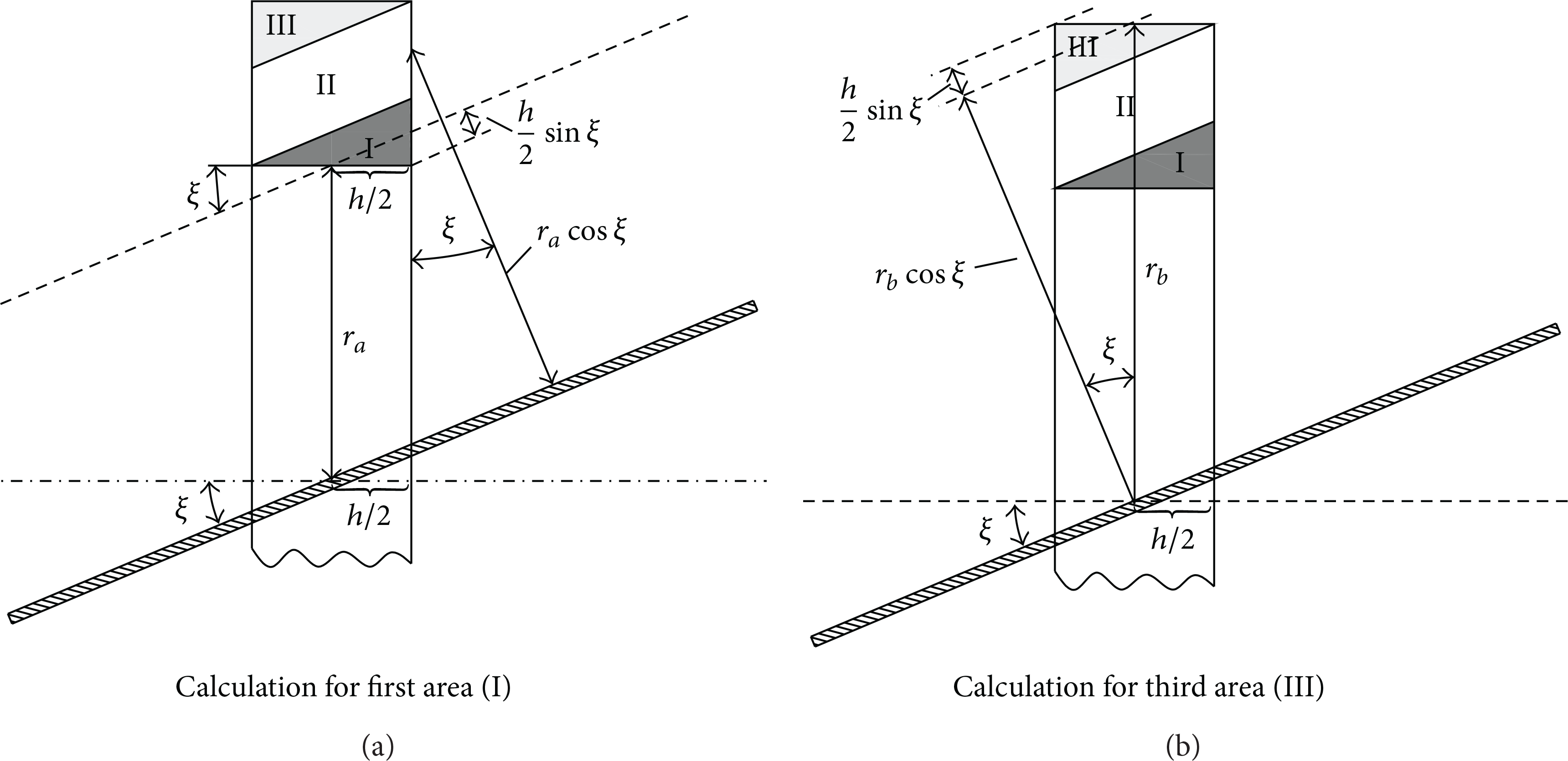
Calculation of the magnetic flux areas.
From further analysis of the geometrical relations follow the radial limits for the areas (I) and (III):

Then, the magnetic fluxes linking quoted areas are given, respectively, as follows:
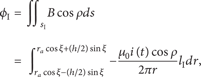
where lI = (r – rImin)(tgξ + ctgξ) is the length of dSI, and

where lII = h/cosξ is the length of dSII.

where lIII = (rIIImax – r)(tgξ + ctgξ) is the length of dSIII.
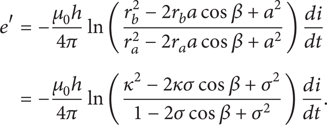
Thus, the induced electromotive force e′ in quoted areas is calculated
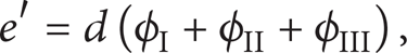
where

Therefore, the electromotive force e′ induced by one turn is
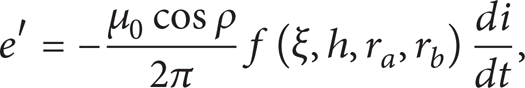
where f = f(ξ, h, r a , r b ) is denoted by
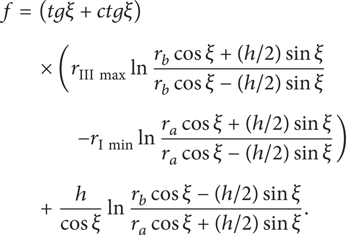
Defining κ = r b /r a , ν = h/2r b , (23) can be rewritten as

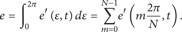
By substituting (15) and (24) into (22), the expression of e′ is the function of λ, ∊, κ, ν, N, and h. Therefore, the final expression for total induced electromotive force e of a real PCBRC model is calculated by integrating ∊ from 0 to 2π. Considering the discrete distribution feature of PCBRCs, it is equal to the sum over all individual turns:
Tilting error δ(λ) is defined by

Finally, the expression of δ is the function of κ, ν, λ, and N.
Provided that N = 200,

Theoretical results:(a) tilting angle λ = π/6, turns N = 200; (b) tilting angle λ = π/16, turns N = 200; (c) tilting angle λ = π/36, turns N = 200; (d) tilting angle λ = π/6, turns N = 500.
Conclusions can be drawn from these results. (1) Tilting position error is smaller when angle λ has lower value. (2) This error might be reduced obviously by decreasing values of κ = r b /r a and ν = h/2r b . (3) The value of turn number plays a relatively small weight to the tilting position error.
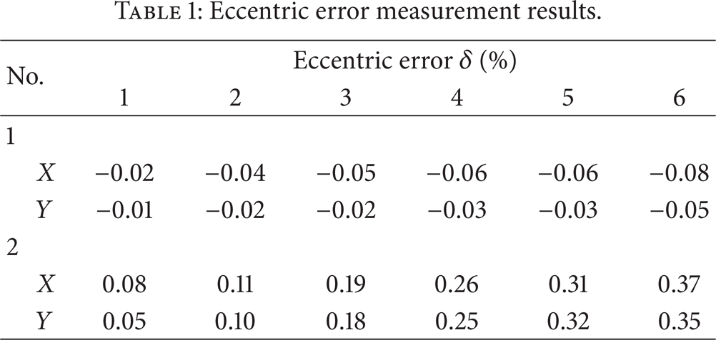
Experimental setup has been built, and positional error measurements have been performed for two practical PCBRCs by fixing the primary current at 100 A and 50 Hz. Number 1 PCBRC is with N of 180, r a of 31 mm, and r b of 45 mm, and number 2 is with N of 135, r a of 22 mm, and r b of 34 mm. The testing points for eccentric positional error measurement are shown in Figure 10. In Position 1, the eccentric factor σ = 0.1, and in Position 6, the eccentric factor σ = 0.6. The eccentric error measurement results are shown in Table 1. The tilting error measurement results are shown in Table 2.
Eccentric error measurement results.
Tilting error measurement results.


The configuration for eccentric position error measurement.
Experimental results verified that critical structure parameters of PCBRCs (such as the value of radii, the number of turns) have influences on the measurement accuracy, and positional errors met the previous error analyses.
4. Conclusions
PCBRC is a promising choice for precise AC current measurement due to its very uniform cross-sectional area and distribution of turns. But mathematical analyses presented in this paper show that positional sensitivities of eccentricity and tilting still contribute to the deviations from expected values. The performed analyses have investigated relationships between critical parameters and positional errors. Results confirm that these errors can be reduced lower than 0.1% by determining the optimal critical structure parameters of the coil, such as the value of inner radius, the ratio of outer radius to inner radius, and the number of turns.