
Abstract
Skid-steered mobile robots have been developed to explore unknown environments, especially in rough terrain situations, where the wheel slips always occur and vary when the robot is traveling with different trajectory shapes. The wheel slippage limits the traction and braking abilities of the robot. In this paper, we propose a new dual estimation algorithm to overcome the previous limitations. The estimated values such as the robot's positions and wheel slips are obtained based on the Kalman filtering technique. As demonstrated by our experimental results, the advantages of the new method are effective to overcome the slip limitations in the path tracking control problem of a four-track wheel skid-steered mobile robot (4-TW SSMR).
1. Introduction
Recently, several studies have proposed and developed various approaches for estimating the position of a mobile robot. For example, one study used an extended Kalman filter (EKF) with a low-cost GPS unit and inclinometer to develop a localization scheme for Ackerman steering vehicles in indoor autonomous navigation situations by estimating the positions of the vehicles and their sensor biases [1]. In another study, a relative localization method was used to determine the navigational route of a convoy of robotic units in an indoor environment using an EKF based on a low-cost laser range system and built-in odometric sensors [2]. In skid-steered vehicles, discrepancies remain between position measurements and the navigational estimations obtained from odometry, infrared, and ultrasonic measurements and Kalman filtering techniques [3]. However, this study only mentioned the advantages of the different extensions of the KF for nonlinear estimations. In [4], a laser range finder (LRF) was used to find the localization of a mobile robot based on the EKF design. That study focused on a statistically exact derivation of the input noise covariance matrix, according to the known noise variances of the angular velocity measurements of both robot wheels.
Additionally, the exploration of unknown planetary surfaces with the help of mobile robot is increasingly being developed. A localization and path selection of any vehicle like a mobile robot to achieve any planetary exploration missions were described in [5]. In this study, by using odometry and gyro measurements, these sensors information was integrated by EKF. In another research, a robot, named Hyperion, was designed for solar-powered operation in polar environments and developed sun-cognizant navigation method to enable rovers to dodge shadows, seek sun, and drive sun-synchronous routes [6].
In a mobile robot's field of operation, wheel slip limits traction and braking ability, especially for a 4-TW SSMR. Accurate estimation of slip is essential to obtain precise position for a mobile robot operating in unstructured terrain, especially in rough terrain situations. Several approaches to slip estimation have been developed. For example, a sliding mode observer (SMO) conducted to estimate slip parameters based on the kinematic model of a skid-steering vehicle is proposed in [7]. In another study, a novel method combining an optical flow algorithm with a sliding mode observer to estimate slip parameters of a SSMR was introduced [8]. Reference [9] proposed an experimental slip model for exact kinematic modeling, and the parameters of this model were determined based on experimental analysis. In [10], a rough-terrain control (RTC) methodology was presented in multi-wheeled mobile robot systems to improve ground traction and reduce power consumption. A key element of the method is able to estimate the wheel ground contact angles.
The methods in [7–9] remain limitations when the robot is traveling on the different ground surfaces with different and longer trajectory shapes. In this paper, we propose a new dual estimation algorithm for the robot's position and wheel slip estimations based on the Kalman filtering technique. First, the EKF is utilized to estimate the robot's positions, velocities and orientation angles, which are used for the feedback control signals. Second, a discrete KF is designed to estimate the slip parameters of the left and right track wheels, which are used to compensate for the velocity constraints and its variance values for the EKF in order to get more accurate estimated values. In the dual estimation algorithm, these two Kalman filters are performed simultaneously based on the measurements from AHRS sensor and two incremental encoders. The experimental results show that the advantages of the new method overcome the slip limitations in the path tracking control problem of a 4-TW SSMR. The experiment is performed on the NT-Hazard Escape-1, as shown in Figure 1.

The NT-Hazard Escape-1 mobile robot.
This paper is organized as follows: Section 2 introduces the experimental setup and implemented control system. Dual estimation algorithm is presented in Section 3. The experimental results, including analysis and evaluation, are discussed in Section 4. Finally, Section 5 presents the conclusion.
2. The Experimental Setup and Implemented Control System
2.1. The Experimental Setup
The NT-Hazard Escape-1 mobile robot, with four NT-track wheels, considered in this study is applied in the investigation of disaster areas, running and watching rough areas including construction site and running up stairways. The robot with small actuators was made for the first time in Korea, providing various functions to robots. Each of the eight motors is faithful to its own move, and the robot can easily lift two tracks even when is fully loaded. The robot can also move while maintaining its central balance, like a tank. In addition, RS232C is supported to enable working with an embedded board and computer through wireless telecommunication. Therefore, it is easily applied in various applications. The dimensions for the mobile robot are shown in Figure 2.

Dimensions of the NT-Hazard Escape-1.
For research purposes, an experimental mobile robot was designed. The system configuration was represented by a configuration for all of the elemental components as shown in Figure 3(a), while the real photograph of the experimental system is displayed in Figure 3(b). From these figures, the AHRS (AHRS-03-300) was mounted on the top and center of the robot based on a base platform. Two incremental encoders (E40H-8-1024-3-N-5) were installed on the robot's front-left and right tracked wheels. A notebook (model ASUS U36S) was used to collect the data from the AHRS sensor and two incremental encoders via an AVR 128-pro board. This notebook also performed all algorithms which were applied in real-time. Here, the control algorithm for the system was coded in C# programming language (using the Microsoft Visual Studio 2008 version).
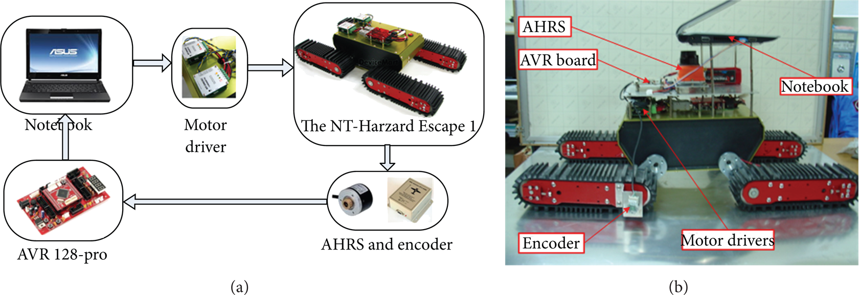
(a) The system configuration. (b) The real photograph of the experimental system.
During the experiment, the measurement sampling frequency for the AHRS and incremental encoders is set to 20 Hz. The robot is programmed to follow a desired trajectory. Based on the measurements from these two sensors, the robot position values are derived through the Kalman filtering technique, and then robot controllers are applied to drive the robot to the desired trajectories.
2.2. The Implemented Control System
In the experimental mobile robot, a path tracking control method for the robot motion is performed to follow the desired trajectory based on closed-loop control systems and the sensor fusion technique for feedback control signals. Figure 4 describes the diagram of the implemented control algorithm. As shown in this figure, the control system includes three closed-loop controls: two low-level closed-loop controls for motor speeds of the left and right sides and one high-level closed-loop control for robot position. The discrete PID controllers are applied for low-level closed-loop controls. For the path tracking control system, the stable tracking control (STC) method is introduced in [11, 12], based on an error model of the kinematical model. In another approach, vector field orientation (VFO) feedback control method is a motivating control technique to calculate such linear and angular velocities for DDVs. The reader can refer to [13] (an application for a Four wheel drive skid-steered mobile robot), [14] (VFO for a DDV) and [15] (an extension of VFO in the case of skid-slip phenomena). In this work, the VFO control feedback method is applied for the high-level closed-loop control of the robot position in a 2D plane.

The diagram of the implemented control system.
Additionally, the dual estimation algorithm is proposed by integrating the EKF and the discrete KF. First, the EKF, denoted by EKF x, is utilized to estimate the positions, velocities and orientation angles which are used for the feedback control signals in the high-level closed-loop control. Second, a discrete KF, denoted by KFλ, is designed to estimate the slip parameters of the left and right track wheels, which are used to compensate the velocity constraints and its variance values for the EKF x in order to get more accurate estimation values. In the dual estimation algorithm, these EKF x and KFλ are performed simultaneously based on the measurements from AHRS sensor and two incremental encoders, and they are introduced in the next sections.
3. Dual Estimation Algorithm
3.1. AHRS Kinematics and Velocity Constraints
We define a navigational reference frame N(X, Y, Z) and robot body frame B(x, y, z) as shown in Figure 5. Let
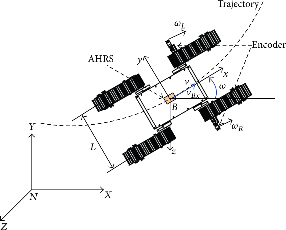
An AHRS kinematics model of a 4-TW SSMR.
After subtracting the constant offset and local gravity vector, the acceleration and angular rate models of the AHRS can be described by [16]

with

where the true acceleration vector, true angular rate vector, acceleration white noise, and angular rate white noise are
We also define the state vector

where C B N and qΘ, the transformation matrix from the B frame to the N frame and transformation matrix of the Euler angles, as given by the following matrices:


where cθ = cosθ, sθ = sinθ, tθ = tanθ, and the same notation convention is used for angles ϕ and ψ.
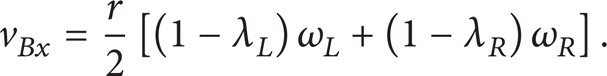
In the 4-TW SSMR, the motors that power the wheels at each side are geared internally to ensure that the velocities of two adjacent wheels at each side are synchronized (have the same angular velocity) and thus have the same velocity at ground contact. Let us define v L and v R asthe left and right linear velocities of the robot; we have

where v1x, v2x, v3x, and v4x are center linear velocities for front-left, rear-left, front-right, and rear-right wheels, respectively, shown in Figure 6. The longitudinal wheel slips of the left and right wheels λ L and λ R are defined as ratios of the wheel velocities and its center velocities [17], as follows:

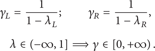
where r is the wheel radius, ω L and ω R are the wheel angular speeds for the left and right sides of the mobile robot. From (7), it can be seen that the wheel slip λ ∊ [0, 1] if the wheel is under traction and λ ∊ (−∞, 0] if the wheel is under braking. Using the definition of the slip in (7), we have


The 4-TW SSMR kinematics.
Because of the symmetric mechanical structure of the robot, it can be assumed that the center of mass (COM) of the robot is located at the center of geometry (COG) of the body frame. The AHRS coordinate is located at the COG in B frame, as shown in Figure 5. Using two wheel encoders, we obtain the AHRS velocity vector
Based on [17], since the four tracked wheels of our robot are always in contact with the ground and since the AHRS is fixed on the robot platform, the velocity constraints v By and v Bz in y-axis and z-axis directions for the AHRS device can be simplified to equal zero.
The noises in the longitudinal velocity v Bx can be expressed as the sum of the noises of the left and right wheels' angular speeds ω L and ω R as measured by encoders. It is assumed that the noises for ω L and ω R have a normal distribution with a zero-mean and corresponding variances, and there is no cross-correlation between the noise of ω R and of ω L [18]. The noise variance of the longitudinal velocity v Bx can be expressed as
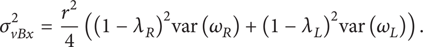
The noise variances σ vBy 2 and σ vBz 2 of the lateral velocity v By and ground surface topography v Bz are also expressed by zeros. In order to obtain the longitudinal velocity v Bx and its noise variance, we have to estimate slips λ L and λ R . The proposed dual estimation method, which can estimate these two slip values, is introduced in Section 3.2.
3.2. Dual Estimation Algorithm
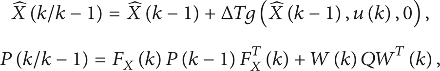
Now, we define the state variable's vector
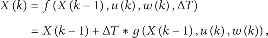
where the AHRS input signals at the kth sampling time is

and w(k) = [waccle(k), wgyros(k), waccbias(k), wgyrobias(k)] T ∊ ℝ12 is the process noise vector.
With velocity constraints (9), the AHRS velocities in B frame are considered as the measurement vector

where n(k) is measurement noises. We assume that the measurement noises n(k) are independent, zero-mean, and Gaussian white noise; that is, n(k) ∼ N(0, R). The covariance matrix of the measurement noise is

where σ vBx 2, σ vBy 2, and σ vBz 2 are calculated in (10). The EKFx was implemented by using systems (11) and (13) in order to obtain the estimated positions, velocities, and attitudes of the robot.
Additionally, in order to determine wheel slip parameters to compensate the velocity constraints and its variance values, a discrete KF, denoted by KFλ, is designed. By giving v
Bx
in body frame B and yaw rate
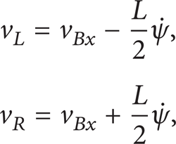
where L is lateral wheel bases. By substituting (15) into (7), we have
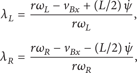
We define unknown parameters as:
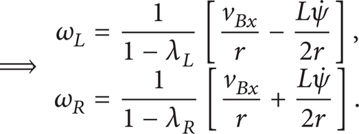
Substituting (18) into (17), the relationship between the angular speed from encoders and unknown parameters is described as

The slip estimation based on the KFλ is now established. Assuming that the slip process is the random process, then the unknown parameter process can be modeled in discrete-time form as

where

From (19), the measurement model of the KFλ can be written relating to the encoder measurement noises as

where

where

where
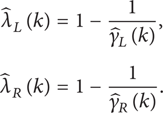
From previous descriptions, the estimated slip values

The dual estimation.
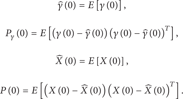
Initialize with
For k ∊ {1, …, ∞}, the prediction step for KFλ is
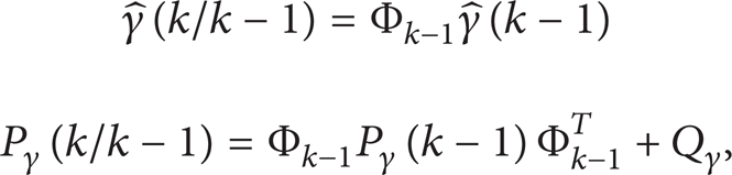
and update step equations for KFλ are

where Qγ and Rγ(k) are the process and measurement covariance matrices of wγ(k) and nγ(k), respectively.
And the prediction step for EKFx is
and update step for EKFx is

where

and Q is the process covariance matrix of w.
Update estimation values
4. Experimental Results
In this section, the experiments are performed to prove the effectiveness of the proposed dual estimation algorithm (DEA) for the robot's path tracking problem in real-time application. The VFO feedback control method is applied for the trajectory tracking control. In fact, the wheel slips, which always occur and vary while the robot is traveling on the different ground surfaces with different trajectory shapes, limit the traction and braking abilities of the robot, especially in 4-TW SSMR. Therefore, a proposed DEA is performed to overcome the previous limitations in this research. The estimated values such as robot's positions, velocities, attitudes and wheel slip parameters are obtained more accurately, which are used for the feedback control signals in the high-level closed-loop control. In this work, the experiments have been carried out on concrete terrain in an outdoor environment, involving two scenarios.
Scenario 1. The mobile robot is controlled to follow a desired trajectory with two curves.
Scenario 2. The mobile robot is controlled to follow a desired circular trajectory with a 2 m radius.
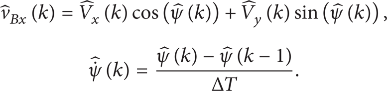
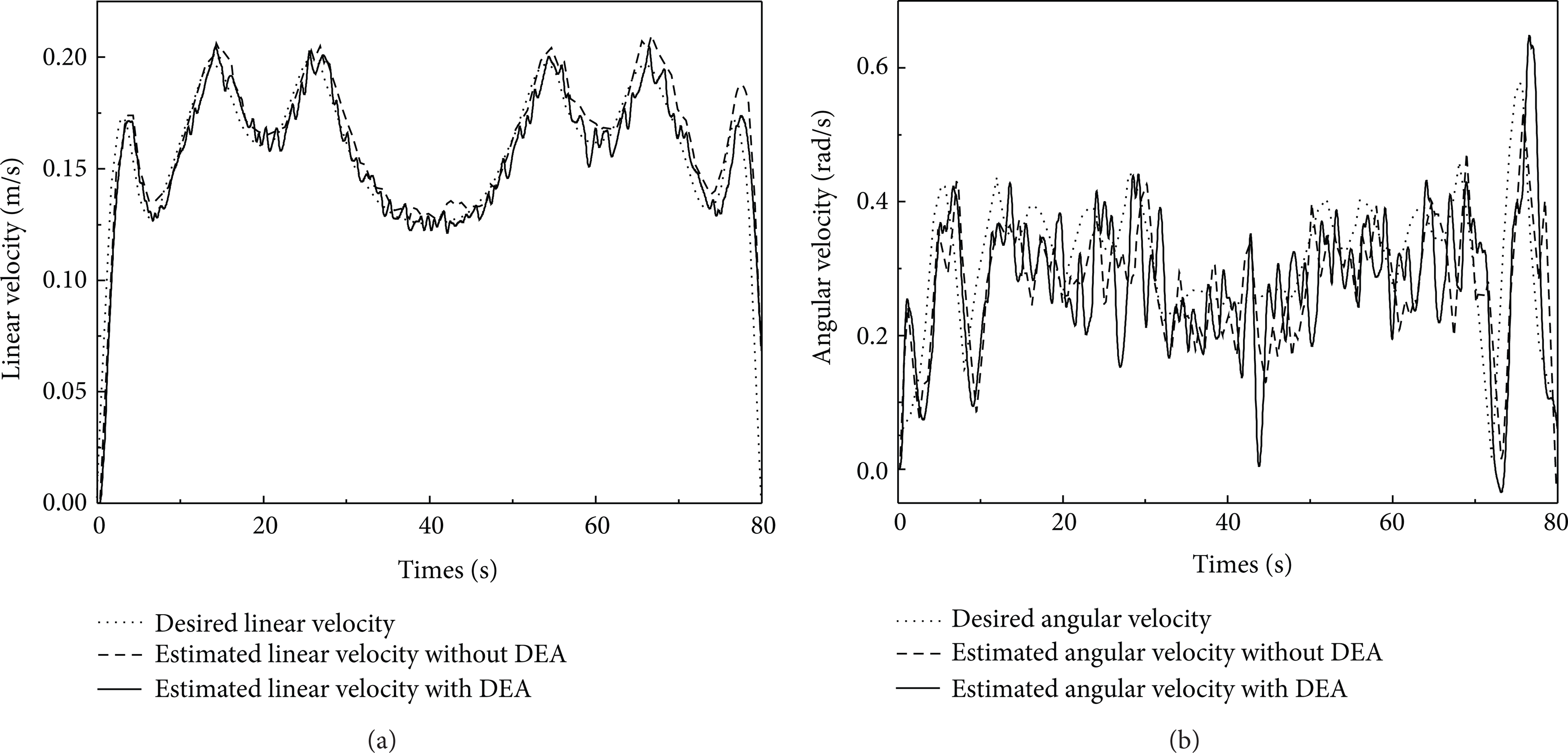
In the first scenario, the output trajectories are shown in Figure 9(a). As illustrated in Figure 9(a), the output response without DEA is quite far to thedesired response while that with DEA is close to the desired response. The linear and angular velocities of two methods (without and with DEA), shown in Figures 8(a) and 8(b), are also close to the desired velocities despite the mechanical vibrations and sensor noises. In fact, although the working environment contains large numbers of nonlinear and uncertain factors, which impact with the system performances, the results point out that the proposed DEA has improved the performance of the path tracking problem. The previous evaluation is proved by considering the position errors as shown in Figure 9(b). In Figure 9(b), the position error with DEA at any instant of time, which is the distance from the estimated position of the robot at the defined instant to the nearest point of the desired trajectory, is the closest to zero compared to that without DEA. Consequently, the root mean square error (RMSE) of robot position with DEA is the smallest (0.0239 [m]), while that without DEA is 0.0845 [m].

(a) The desired and estimated linear velocities without and with DEA in scenario 1. (b) The desired and estimated angular velocities without and with DEA in scenario 1.

(a) The desired trajectory, estimated trajectories without and with DEA in scenario 1. (b) The position errors without and with DEA in scenario 1.
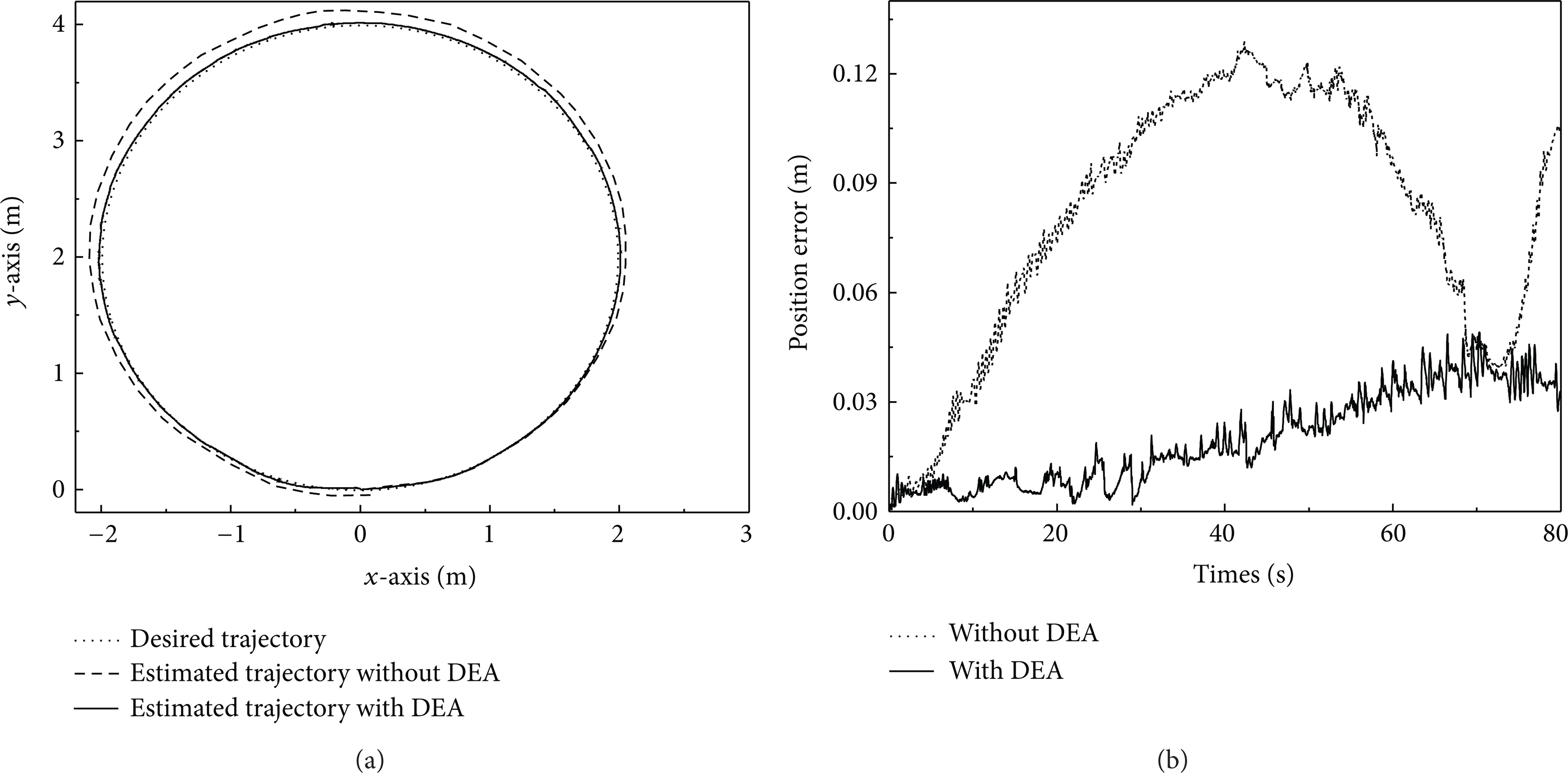
In order to evaluate the proposed method, the system is also tested with a circular trajectory, in the second scenario. The output responses without and with DEA are shown in Figure 11(a). It can see that the response with DEA is still the closest to the desired response. The linear and angular velocities are shown in Figures 10(a) and 10(b). Figure 11(b) clearly depicts that the result with DEA is the best while comparing to that without DEA; the position error graph with DEA is still the closest to zero. Hence, the RMSE of robot position with DEA is the smallest (0.0236 [m]), while that without DEA is 0.0882 [m].
(a) The desired and estimated linear velocities in scenario 2. (b) The desired and estimated angular velocities in scenario 2.
(a) The desired trajectory and estimated trajectories without and with DEA in scenario 2. (b) The position errors without and with DEA in scenario 2.
In both scenarios, the results show that the trajectories with DEA are the closest to the desired responses. It results from the estimated slip values which are used to compensate the velocity constraints and its variances. The estimated values in EKFx such as velocities and trajectories with DEA are more precise than those without DEA. It means that the feedback control signals with DEA are more accurate, and then the high-level closed-loop control with DEA performs better than the previous testbed without DEA.
From the previous analyses, the robot positioning results with DEA are better than the previous results without DEA. It is clear that the DEA, with wheel slip compensation, is very essential in the mobile robot field. For the first scenario, the robot follows the desired trajectory, which has two curves. At the left rotation in the first curve, the angular speed of the right wheels is greater than that of the left wheels. Then, the traction phenomenon occurs on the right side, while the braking phenomenon appears on the left. Consequently, the slip value of the right wheels is positive, and that of the left wheels is negative. Similarly, at the right rotation in the second curve, the slip value of the right wheels is negative while that of the left side is positive. Furthermore, when the robot travels along the straight segment in the first trajectory, less force is needed to drive the robot and the left and right wheel slips are close to zero. Figure 12(a) illustrates the estimated slip parameters of the left and right wheels in the first scenario.

The estimated slip parameters of the left and right wheels in scenarios 1 (a) and 2 (b).
For the second scenario, the robot follows the desired circular trajectory with counterclockwise direction. The angular speed of the right wheels is always larger than that of the left wheels. Consequently, the slip value of the right wheels is always positive and that of the left wheels is always negative, as shown in Figure 12 (b). All types of the estimated slip values in both scenarios are consistent. On the whole, the robot positioning results are improved significantly by considering the new dual estimation method. Table 1 shows RMSEs of all experiments in this work; the RMSE values with DEA are reduced more significantly.
RMSEs of all experiments.

5. Conclusion
This paper presents experiments to control the 4-TW SSMR based on the estimated feedback control signals. In the mobile robot field, the wheel slip limits the traction and braking ability of the robot, especially the 4-TW SSMR. The wheel slip always occurs while the robot is traveling on the different ground surfaces with different trajectory shapes. In this paper, we propose the new dual estimation algorithm for robot's positions, velocities, attitudes, and wheel slip parameters based on the Kalman filtering technique in order to obtain more accurate estimation values, which are used for the feedback control signals. In the dual estimation algorithm, two Kalman filters performed simultaneously based on the measurements from AHRS sensor and two incremental encoders. Experimental results show the advantages of the novel method which is effective in the path tracking control problem for a 4-TW SSMR, for example, the commercialized Hazard Escape I mobile robot.
Conflict of Interests
This company does not have any relationship with the name of Hazard Escape 1. So there is no competing interest such as financial gain between two sides.
Footnotes
Acknowledgment
This research was supported by Korea Aerospace Research Institute in 2012.